Bitzer ECOLITE LHL3E/2EES-2Y User manual

KB-206-1
ECOLITE
Air-cooled condensing units with capacity-controlled ECOLINE compressors
English....................................................................................................................................................... 2
ECOLITE
Luftgekühlte Verflüssigungssätze mit leistungsgeregelten ECOLINE Verdichtern
Deutsch ..................................................................................................................................................... 33
ECOLITE
Groupes de condensation refroidis par air avec compresseurs ECOLINE dotés d’une fonction de régu-
lation de puissance
Français..................................................................................................................................................... 64
LHL3E/2EES-2Y
LHL3E/2DES-2Y
LHL3E/2CES-3Y
LHL5E/4FES-3Y
LHL5E/4EES-4Y
LHL5E/4DES-5Y
LHL5E/4CES-6Y
Document for installers
Dokument für Monteure
Document pour des monteurs

KB-206-12
Table of contents
1 Introduction............................................................................................................................................................3
1.1 Also observe the following technical documents ...........................................................................................3
2 Safety ....................................................................................................................................................................3
2.1 Authorized staff..............................................................................................................................................3
2.2 Residual risks ................................................................................................................................................3
2.3 Safety references...........................................................................................................................................3
2.3.1 General safety references.................................................................................................................. 4
3 Classification of the condensing units and of its components according to the EU directives ..............................5
4 State of delivery and schematic design of the ECOLITE condensing units...........................................................7
5 Application ranges.................................................................................................................................................8
5.1 Maximum allowable pressure ........................................................................................................................8
6 Mounting................................................................................................................................................................9
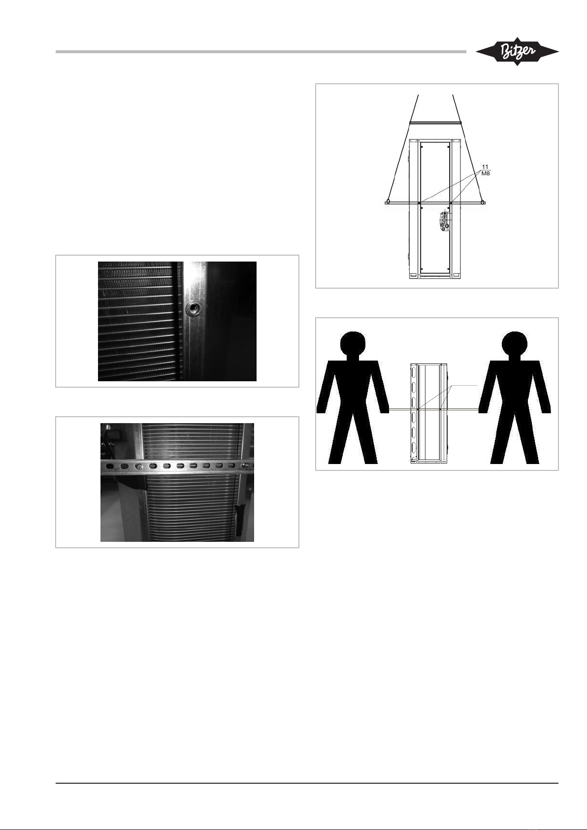
6.1 Transporting the condensing unit ..................................................................................................................9
6.1.1 Transport locks for condensing units ................................................................................................. 9
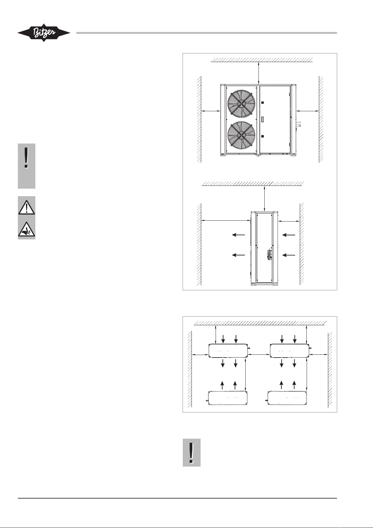
6.2 Installing the condensing unit ........................................................................................................................9
6.3 Pipelines ......................................................................................................................................................11
6.4 Incorporation of the condensing unit into the refrigeration system ..............................................................11
6.5 Connections and dimensional drawing........................................................................................................12
7 Electrical connection............................................................................................................................................13
7.1 Schematic wiring diagram for ECOLITE condensing units..........................................................................13
8 Commissioning ....................................................................................................................................................15
8.1 Setting the controller....................................................................................................................................15
8.1.1 Function keys................................................................................................................................... 16
8.1.2 Display ............................................................................................................................................. 16
8.1.3 First switching on of the power supply ............................................................................................. 17
8.1.4 Status menu..................................................................................................................................... 17
8.1.5 Programming menu ......................................................................................................................... 22
8.1.6 BIOS menu ...................................................................................................................................... 29
8.1.7 Alarm messages .............................................................................................................................. 30
8.1.8 Communication ................................................................................................................................ 31
9 Operation.............................................................................................................................................................31
9.1 Regular tests................................................................................................................................................31
10 Decommissioning ................................................................................................................................................32
10.1 Standstill ......................................................................................................................................................32
10.2 Disassembly of the condensing unit or of components ...............................................................................32
10.3 Drain oil........................................................................................................................................................32
10.4 Remove or dispose of the compressor and other components ...................................................................32

KB-206-1 3
1 Introduction
These condensing units are intended for incorporation
into refrigeration systems in accordance with the EU
Machinery Directive 2006/42/EC. They may only be put
into operation if they have been installed into the refri-
geration systems according to these mounting/operat-
ing instructions and if the overall system complies with
the applicable legal provisions.
The condensing units have been built in accordance
with state-of-the-art methods and the applicable regula-
tions. Particular importance has been placed on user
safety.
The electrical components correspond to the EU Low
Voltage Directive 2014/35/EU, frequency inverters cor-
respond also to the EU EMC Directive 2014/30/EU.
Moreover, the pressurised components must comply
with the EU Pressure Equipment Directives 2014/68/
EU (PED) (see table 1, page 5).
These operating instructions must be kept available
near the refrigeration system during the whole lifetime
of the condensing unit.
1.1 Also observe the following technical documents
In addition to these instructions, the operating instruc-
tions and Technical Information for the respective com-
pressors and pressure vessels must be taken into ac-
count.
• KB-104 operating instructions BITZER ECOLINE
• DB-300 pressure vessel: Liquid receivers and oil
separators
• KT-101 CR II system / capacity control for
BITZER ECOLINE
• The manufacturer's documentation of the individual
components included in the scope of delivery
2 Safety
2.1 Authorized staff
All work done on compressors and refrigeration sys-
tems may only be performed by qualified and author-
ized staff who have been trained and instructed accord-
ingly. The qualification and expert knowledge of the
personnel must correspond to the local regulations and
guidelines.
2.2 Residual risks
The individual components of the condensing unit may
present unavoidable residual risks. That is why any
person working on this device must carefully read these
operating instructions!
The following regulations shall apply:
• the relevant safety regulations and standards (e.g.
EN378, EN60204 and EN60335),
• the generally accepted safety rules,
• the EU directives,
• national regulations.
2.3 Safety references
are instructions intended to prevent hazards. Safety ref-
erences must be stringently observed!
!
!
NOTICE
Safety reference to avoid situations which may
result in damage to a device or its equipment.
CAUTION
Safety reference to avoid a potentially hazard-
ous situation which may result in minor or mod-
erate injury.
WARNING
Safety reference to avoid a potentially hazard-
ous situation which could result in death or seri-
ous injury.
DANGER
Safety reference to avoid an imminently hazard-
ous situation which may result in death or seri-
ous injury.

KB-206-14
2.3.1 General safety references
State of delivery
CAUTION
The condensing unit is filled with a protective
charge: Excess pressure 0.2..0.5 bar.
Risk of injury to skin and eyes.
Depressurise the condensing unit!
Wear safety goggles!
For work on the condensing unit once it has been
commissioned
WARNING
Compressors or other components of the con-
densing units may be under pressure!
Serious injuries are possible.
Depressurise all relevant components!
Wear safety goggles!
CAUTION
Surface temperatures of more than 60°C or be-
low 0°C.
Risk of burns or frostbite.
Shut off accessible areas and mark them.
Before performing any work on the condensing
unit: Switch it off and let it cool down.
CAUTION
The fins of the condenser have sharp edges!
Risk of lacerations.
Before performing any work on the condensing
unit: Wear protective gloves.
When working on the fans of the heat exchangers: Ob-
serve the operating instructions of the fan manufac-
turer!
DANGER
Rotating fan blades!
Body parts may be injured, bone fractures!
Clothes may be caught and drawn into the pro-
tective grating!
Work on the fan only when it is at standstill!

KB-206-1 5
3 Classification of the condensing units and of its
components according to the EU directives
The condensing units are intended for incorporation
into machines in accordance with the EU Machinery
Directive 2006/42/EC. The electrical components com-
ply with the EU Low Voltage Directive 2014/35/EU. For
the incorporated pressurised components, the EU
Pressure Equipment Directive 2014/68/EU (PED) may
be applicable, except for the compressors (see below).
The corresponding declarations of conformity and man-
ufacturers’ declarations are available. Classification of
the individual components and additional explanations
see table 1, page 5.
Information
Condensing units are not considered a “func-
tional whole” according to the PED and do
therefore not fall within the scope of Art.1 §
2.1.5 “Assemblies”. The directive is therefore
only applied to the individual components. The
same applies to the CE marking. Assessment
by a notified body: Bureau Veritas, Paris –
"Technical Appraisal" for ASERCOM members
PED-TA_ASE_001_01-DEU.
Information
According to Article 4 § 3.10, semi-hermetic and
open drive compressors are excluded from the
application range of the PED. This exception is
confirmed by the evaluation of a notified body.
Please refer to "Explanations about the product
conformity" AC-100 for further explanations.
Please refer to AC-100 for the classification of
pressurised accessories for compressors.
Component PED ① MD LVD EMC CE mark-
ing
Comments
Compressor, semi-her-
metic
Art. 4
(3.10)
X X X Accessories, see explanation
AC-100
Discharge gas shut-off
valve
Art. 4 (3) ≤ DN25 / PS 32 bar
Suction gas shut-off valve Art. 4 (3) ≤ DN32 / PS 32 bar
Condenser, air-cooled Art. 4 (3) ≤ DN25 / PS 32 bar
Condenser fan Art. 4 (3) X X
Liquid line, condensate
line
Pipe joints
Art. 4 (3)
I/II
X ② ≤ DN25 / PS 32 bar, detachable
joint ②
≤ DN32 permanent joint ②
Discharge gas line
Pipe joints
Art. 4 (3) ≤ DN25 / PS 32 bar
according to DN
Suction gas line
Pipe joints
Art. 4 (3) ≤ DN25 / PS 19 bar
Detachable joint ≤ DN25
Liquid receiver II < 6.25 .. 31.25 dm3 / PS 32 bar
Liquid shut-off valve Art. 4 (3) ≤ DN25 / PS 32 bar
Ball valve Art. 4 (3)
Oil separator I X < 6.25 dm3 / PS 32 bar
Check valve Art. 4 (3) ≤ DN32 / PS 32 bar
Filter drier Art. 4 (3) < 1.56 dm3 / PS 32 bar
Sight glass Art. 4 (3) < 1 dm3 / PS 32 bar
HP limiter/
HP cut-out
IV With safety function
LP limiter IV With safety function
Discharge gas temperat-
ure sensor
Art. 4 (3) ≤ DN25

KB-206-16
Component PED ① MD LVD EMC CE mark-
ing
Comments
Suction gas temperature
sensor
Art. 4 (3) ≤ DN25
Solenoid valve with injec-
tion nozzle (RI)
Art. 4 (3) ≤ DN25
CRII capacity control Art. 4 (3) ≤ DN25
Tab.1: Classification of the ECOLITE components according to the EU directive
PED 2014/68/EU, MD 2006/42/EG, LVD 2014/35/EU,
EMC 2014/30/EU
① Fluid group 2 according to PED (refrigerant group
L1 / EN378). Maximum allowable pressure PS: 32 bar
(HP), 19 bar (LP)
② Receiver according to category II, procedure accord-
ing to Art. 3.1.2, CE marking on the receiver

KB-206-1 7
4 State of delivery and schematic design of the
ECOLITE condensing units
• Protective gas charge: Excess pressure approx.
0.2.. 0.5 bar.
• For the technical data, see brochures of the con-
densing units: KP-206.
18
6
113
1b
10
4b
12
4
3
2a
2
5a
8
22
19
8a
9
23
1a
11
25
26
Fig.1: Schematic design of the ECOLITE condensing units (example shows LHL5E/4FES-3Y .. LHL5E/4CES-6Y)

KB-206-18
Component Scope of delivery
Stand. Opt.
1 Compressor, semi-hermetic x
1a Discharge gas shut-off valve x
1b Suction gas shut-off valve x
2 Condenser, air-cooled x
2a Condenser fan x
3 Condensate line x
4 Liquid receiver x
4b Ball valve x
5a Terminal box/controller of
the condensing unit
x
6 Discharge gas line x
8 Oil separator x
8a Oil monitoring OLC-K1 x
9 Check valve x
10 Liquid line x
11 Filter drier x
12 Sight glass x
13 Suction gas line (insulated) x
18 HP limiter/ HP cut-out x
19 LP limiter x
22 Discharge gas temperature
sensor
x
23 Suction gas temperature
sensor
x
25 CRII capacity control
1 x standard for
LHL3E/2EES-2Y ..
LHL5E/4CES-6Y
1 x standard + 1 x option for
LHL5E/4FES-3Y ..
LHL5E/4CES-6Y
x x
26 Ambient temperature sensor x
Tab.2: Legend and state of delivery ECOLITE condensing units
5 Application ranges
Permitted refrigerant R134a, R404A, R407A,
R407C, R407F, R448A,
R449A, R450A, R507A,
R513A, R22
Oil charge ① tc < 70°C BITZER BSE32
Maximum allowable pres-
sure (PS)
LP: 19 bar, HP: 32 bar
Maximum permitted ambi-
ent temperature
-20°C .. +50°C
For application limits, see brochure KP-104 or BITZER
software.
① For alternative oils, see Technical Information
KT-510.
WARNING
Risk of bursting due to counterfeit refrigerants!
Serious injuries are possible!
Purchase refrigerants only from reputable man-
ufacturers and reliable distributors!
5.1 Maximum allowable pressure
The whole system must be designed and operated
such that the maximum allowable pressure (PS) cannot
be exceeded in any part of the system (see name plate
details).
Pressure relief valves on receivers (pressure vessels)
are absolutely necessary if:
• it is to be expected that the maximum allowable
pressure will be exceeded due to external heat
sources (e.g. fire).
• the entire refrigerant charge of the system is more
than 90% of the pressure vessel volume at 20°C (ca-
pacity). The vessel volume is defined as the volume
between the valves upstream and downstream of a
pressure vessel lockable during normal operation.
• the entire refrigerant charge of the system is more
than 90% of the pressure vessel volume at 20°C (ca-
pacity). The vessel volume is defined as the volume
between the valves upstream and downstream of a
pressure vessel lockable during normal operation.
• a check valve is located between condenser and re-
ceiver.
Safety switching devices
According to local regulations, additional pressure-limit-
ing safety devices must be provided.

KB-206-1 9
6 Mounting
6.1 Transporting the condensing unit
Fix either screw-in eyes or rails with screws on the four
load suspension points. The screw-in eyes and screws
must not exceed a maximum screw-in thread length of
30mm because otherwise the condenser may become
damaged! Screw-in eyes, screws and rails are not in-
cluded in the scope of delivery.
Lift the condensing unit either by means of the lifting
slings by crane or forklift or by hand directly on the
rails.
Fig.2: Load suspension points M8x30 (max.)
Fig.3: Transport rail
Fig.4: Lifting on lifting slings by forklift or crane
M8x30 (max.)
Fig.5: Lifting on transport rail by hand
6.1.1 Transport locks for condensing units
To avoid transport damage to condensing units in their
state of delivery, the vibration dampers of the com-
pressors are blocked by transport locks. It is absolutely
necessary to remove or loosen these locks after mount-
ing. For this, see the operating instructions of the com-
pressor KB-104.
6.2 Installing the condensing unit
The place of installation must have sufficient load-car-
rying capacity and must be level and vibration-resistant.
The minimum distances to fixed delimiting surfaces
must be complied with. Avoid a short-circuit of the air
flow or obstacles in the air flow of the condenser fans!
During the system design, take the minimum and max-
imum load into account. Execute the pipe works and
rising lines according to the generally known rules for
compound systems. Contact BITZER if the system is

KB-206-110
operated under extreme conditions (e.g. aggressive at-
mosphere, low outdoor temperatures, etc.).
Ensure good accessibility for maintenance and service
work!
If the ECOLITE condensing unit is mounted on mount-
ing brackets, the installation surface under the four fix-
ing points must be at least 6 x 6 cm. Use three mount-
ing brackets (on the right, in the middle and on the left).
It is not necessary to screw the bracket in the middle to
the device.
!
!
NOTICE
When installing the condensing unit in areas
where extreme wind loads may occur, screw it
always firmly to the ground!
If installed on a roof, provide sufficient lightning
protection!
CAUTION
The fins of the condenser have sharp edges!
Risk of lacerations.
Before performing any work on the condensing
unit: Wear protective gloves.
50 cm
50 cm30 cm
50 cm
200 cm ≥ 30 cm
Fig.6: Minimum distances to the wall and ceiling (example shows
LHL5E/ .. )
≥ 100 cm
30 cm
≥30 cm
50 cm
≥30 cm
≥300 cm
≥300 cm
Fig.7: Minimum distances when installing several condensing units
(example shows LHL5E/ .. )
!
!
NOTICE
Avoid a short-circuit of the air flow or obstacles
in the air flow of the condenser fans!

KB-206-1 11
6.3 Pipelines
The pipelines must be as short as possible in order to
minimise pressure drops and to keep the refrigerant
quantity available in the pipeline system as low as pos-
sible.
!
!
NOTICE
During soldering work on the suction gas line,
protect the low pressure transmitter against ex-
cess heat (max. 120°C)!
6.4 Incorporation of the condensing unit into the
refrigeration system
If the ECOLITE condensing unit is positioned above the
evaporator, the suction gas line must be executed ac-
cordingly. In case of a long suction gas line or several
evaporators, the use of the optionally available oil sep-
arator and OLC is recommended.
When using an LHL5E with only one capacity-con-
trolled cylinder bank, the suction gas line must be ex-
ecuted such that the oil return is guaranteed even at a
minimum capacity of 50%.
If the ECOLITE condensing unit is positioned below the
evaporator, an additional subcooler should be provided
(example see figure 9, page 11).
6
7
7
2
4
5
1
Fig.8: Mounting of the ECOLITE above the evaporator
6
4
1
2
5
3
Fig.9: Mounting of the ECOLITE below the evaporator
Connection positions
1 ECOLITE condensing unit
2 Evaporator
3 Additional subcooler
4 Expansion valve
5 Liquid line
6 Suction gas line
7 Oil syphon
Tab.3: Connection positions

KB-206-112
6.5 Connections and dimensional drawing
1
ØB
ØA
Y
X
648 80648
46
63
12
C
403
305
450
4
411
M8x30 (max.)
11
M8x30 (max.)
1253
1300
Fig.10: Connection positions (example shows LHL5E/4FES-3Y .. LHL5E/4CES-6Y)
Type ØA ØB C X Y
mm mm mm mm mm
LHL3E/2EES-2Y ..
LHL3E/2CES-3Y
22 12 830 520 575
LHL5E/4FES-3Y ..
LHL5E/4CES-6Y
28 16 1230 520 575
Connection positions
1 Refrigerant inlet (suction gas line)
4 Refrigerant outlet (liquid line)
11 Load suspension points (maximum screw-in
thread length of the screws and the screw-in
eyes: 30 mm)
Tab.4: Connection positions

KB-206-1 13
7 Electrical connection
Semi-hermetic compressor, condenser fan and elec-
trical accessories correspond to the EU Low Voltage
Directive 2014/35/EU.
The ECOLITE condensing unit is provided exclusively
for the connection to TN-C-S or TN-S three-phase
power supply systems with a nominal voltage 230/400
V Δ/Y at a nominal frequency of 50 Hz. The connection
of a neutral conductor is mandatory. A nominal supply
voltage with qualitative characteristics according to DIN
EN 50160 is required. The ECOLITE condensing unit is
provided for a stationary installation.
Type Recommen-
ded fuse
Setting mo-
tor protec-
tion switch
LHL3E/2EES-2(Y) 18 A 8.0 A
LHL3E/2DES-2(Y) 10 A 9.5 A
LHL3E/2CES-3(Y) 13 A 11.0 A
LHL5E/4FES-3(Y) 13 A 11.5 A
LHL5E/4EES-4(Y) 16 A 14.5 A
LHL5E/4DES-5(Y) 16 A 16.0 A
LHL5E/4CES-6(Y) 20 A 20.0 A
Depending on the local conditions and applicable regu-
lations, the installation of a supply circuit disconnecting
device must be provided on site. The service switch
provided in the ECOLITE condensing unit does nor-
mally not fulfil the requirements regarding an electrical
disconnection of the device.
7.1 Schematic wiring diagram for ECOLITE
condensing units
Abbr. Component
B1 Controller
B3 High pressure transmitter (liquid line)
B4 Low pressure transmitter (suction gas
line)
C1 Operating capacitor fan 1
C2 Operating capacitor fan 2
F2 Fuse rating 230V
F3 Control circuit fuse
F5 High pressure switch
F6 Low pressure switch
K1 Main contactor
M1 Compressor
M1E Oil heater
M1Y1 CRII SV1
M1Y2 CRII SV2
M2 Fan 1
M3 Fan 2
OLC-K1 Oil monitoring
Q1 Service switch
R3 Discharge gas temperature sensor
R4 Ambient temperature sensor
R5 Cold store temperature sensor
R8 Suction gas temperature sensor
SE-B1 Protection device
T1 Control transformer
V1 Fan control module
Tab.5: Legend schematic wiring diagram ECOLITE

KB-206-114
CM
3
4
5
6
7
L3
"Ql -KA - \-
It? I TI I
-Kl
: ? ]
21
lT3 IT2 'TI 'n/8.6 2 4 6
- l* u_l
-R6
-X6
6 I 3
i GMYE
1
2 6 A
-X3
-F3
T500mA
-N2
-TI
-CI
4 iF
-XI
<A\
-S12
H
[]
230
24V
OV ~
230V-
OV
n.„ n
-C2
4]jiF
-X2
415
0.
-M2
/M
-M3
-X3
2j 5
3
-M4
-Bl
+ G
RS485
N
D03
D02
DOl
TC2
TC2
TCl TCl
0 0
0
0
0 0
0
0
Fl
F2
I
F5
I
Prg
F3
4 G 3 5
-Kl
i'
4 U T 2 T 3 T 4
SE-Bl
OLC-Kl
-Y3-1 -Y3-2
& f
-F5
[
-F6
-N2
/8.3
im Lo
Dil
-X8
-R3
13
¦Kl\
/8.6 14
-R4
AI 3
n
AI 5
DI6
-R8
-xio V
6 s I 7
-X9
-B3
-R5
.43 ,4 ,41
AOl
12Vdc
D05
5Vdc
Supp.
Supp.
?2 Y Y Y Y
-B4
4t
I I
wire umper must
max. lOVA
Don t mix 12V= and 230V' voltage!
Power supply Compressor
3/N/PE 400VAC max. 17 7A
50/60HZ
max. 32A
on site
Oil
heater
Capacity control Door Fan(s)
SV 1 SV 2 switch 1(lower) 2(upper)
(Option) (LHL5E only)
(LHL5E only)
Additional
fan
Motor
protection
device
Oil level High press. Low press. Discharge Ambient Suction Coldstore High pressure Low pressure External I/O
protection de ice switch
(Option)
(LHL5E only)
limiter gas temp. temp.
sensor sensor
temp. temp.
sensor sensor
(Disconnect R8
if used)
transmitter
transmrtter m-i
M-l
o ü
U
> e
I I
fti f
Datum
01.09.2017
B
31.01.18
Rathmann
Bearb.
Rathmann
A
23.11.17
Rathmann
Gepr.
Zust.
Änderung
Datum
Name
Norm
BITZER Kühlmaschinenbau Schkeuditz GmbH
Industriestrasse 48
04435 Schkeuditz
Deutschland / Germany
Urspr.
Ers. f
Ers. d
E C 0 L I T E
LHL3E / LHL5E
Circuit diagram
200186639 001
LHL3E / LHL5E
Page 1
of 1 Pages
Fig.11: Schematic wiring diagram ECOLITE condensing units

KB-206-1 15
8 Commissioning
For detailed description, please refer to the operating
instructions KB-104 of the compressor:
• Check tightness
• Evacuate
• Refrigerant charge
• Checks before starting
• Compressor start
• Settings on the controller
8.1 Setting the controller
Before commissioning the condensing unit, the follow-
ing parameters must be set:
• Refrigerant used
• Retrofitted options
• Provided control according to suction pressure or
cold store temperature
Moreover, parameters for controlling the speed of the
fan, influencing the [ECOLITE] controller via the super-
ior system controller, etc., can be adjusted.
The ECOLITE controller has four function keys for the
operation and the diagnostics and a colour display on
the top of the device.
Fig.12: ECOLITE Controller user interface
Menu Functions
Status menu • Activation / deactivation of the ECOLITE controller
• Display of the status of the condensing unit
• Display of the active set points
• Display of the current measured values (analogue inputs of the controller)
• Display of the current states of the digital inputs of the controller
• Display of the operating time for compressor and CR II capacity regulator
• Display of the historical alarms (20 memory locations)
• Display and setting of date and time of the controller
• Display of the active alarm
Programming menu • Settings regarding the system configuration and the ECOLITE condensing unit
• Settings regarding the control of the compressor and the CR II
• Settings regarding the control of the fans
• Settings for the cold store control
• Settings for the emergency service
• Settings for the monitoring of the application limits
• Setting the function of the digital inputs for external signals
• Setting the function of the signalling LEDs 1 to 7 of the display
BIOS menu • Display of the status of the analogue inputs of the controller
• Display of the status of the digital inputs of the controller
• Display of the status of the analogue outputs of the controller

KB-206-116
Menu Functions
• Display of the status of the digital outputs of the controller
• Display of the internal time and date of the controller
8.1.1 Function keys
Key Function
F1 (⇑) • Increases the value
• Goes to the next menu of the same menu level
• Switches the main display to information on the high pressure side of the condensing
unit
Holding down the key for more than 5 seconds:
• Resets the alarm buffer
F3 (⇓) • Reduces the value
• Goes to the previous menu of the same menu level
• Switches the main display to information on the suction side of the condensing unit
F2 (esc) • Quits the menu without saving the value
• Goes to the next higher menu level
• Switches the main display from the pressure value in bar to the saturation temperature
in °C for the active refrigerant
F4 (set) • Confirms and saves the value
• Goes to the next lower menu level
• Opens the status menu with the main display being active
8.1.2 Display
The user interface consists of a display or input field in
the middle and three status bars at the top, left and bot-
tom sides of the display.
Status bar at the top and right sides of the display:
Symbol Function in the main display
• Alarm active
☼ + • Display of high pressure in bar
☼ + • Display of high pressure as condensing temperature in °C
❅ + • Display of suction pressure in bar
❅ + • Display of suction pressure as evaporation temperature in °C
Status bar at the bottom of the display:
Symbol Function in the main display
① Compressor status
Flashing = compressor will start in a few seconds
On = compressor in operation
Off = compressor not in operation

KB-206-1 17
Symbol Function in the main display
② Status of CR II solenoid valve 1
On = cylinder bank deactivated
Off = cylinder bank activated
③ Status of CR II solenoid valve 2
On = cylinder bank deactivated
Off = cylinder bank activated
④ Status of condenser fan(s)
On = condenser fan(s) in operation
Off = condenser fan(s) not in operation
⑤ Liquid valve status
On = liquid valve switched on
Off = liquid valve switched off
⑥ Operation mode condenser fan(s)
On = operation mode LowSound activated
Off = operation mode Eco activated
⑦ Status of fault message relay
On = fault active
Off = no fault active
8.1.3 First switching on of the power supply
After switching on the power supply, the controller car-
ries out an automatic self-test. In doing so, the display
flashes.
Ex factory the operation of the controller in a newly de-
livered ECOLITE condensing unit is not enabled and,
for this reason, the display should show the status
“OFF” after having switched on the supply voltage.
After parametrisation of the controller, the enable can
take place by means of the parameter OnOF (F4⇒in-
it⇒OnOF) if the commissioning of the refrigerant circuit
allows it.
The condensing unit can also be enabled by means of
an external signal (potential-free relay contact). For
this, a digital input of the controller has to be configured
for the external enable of the condensing unit. This
function is not activated ex factory.
8.1.4 Status menu
Menu item Function
F4⇒init⇒OnOF
Modbus: 16467
(read and write)
Activation / deactivation of the ECOLITE controller
OFF = controller deactivated
On = controller activated
Setting ex factory: OFF = controller deactivated
Display of the status of the condensing unit:
Menu item Function
F4⇒StAt⇒Unit
Modbus: 8989
(read and write)
Displays of the status of the condensing unit
OFF = condensing unit off
On = condensing unit on

KB-206-118
Display of the active software:
Menu item Function
F4⇒SEt⇒SP1
Modbus: 16388
(read and write)
Set point of suction pressure controller
-45.0 – 22.5°C
Setting ex factory: -10.0°C
F4⇒SEt⇒SP2
Modbus: 16407
(read and write)
Set point of condensing pressure controller (without correction)
10.0 – 80.0°C
Setting ex factory: 30.0°C
F4⇒SEt⇒SP3
Modbus: 16408
(read and write)
Maximum condensing pressure
10.0 – 80.0°C
Setting ex factory: 60.0°C
F4⇒SEt⇒SP4
Modbus: 16424
(read and write)
Set point of cold store temperature controller
-40.0 – 22.5°C
Setting ex factory: 2.0°C
Display of the current measured values (analogue
inputs of the controller):
Menu item Function
F4⇒Ai⇒Prt
Modbus: 8966
(read only)
Suction pressure actual value (as saturation temperature)
F4⇒Ai⇒tSC
Modbus: 8961
(read only)
Suction gas temperature actual value
F4⇒Ai⇒dPrt
Modbus: 8967
(read only)
Condensing pressure actual value (as saturation temperature)
F4⇒Ai⇒tCd
Modbus: 8963
(read only)
Discharge gas temperature actual value
F4⇒Ai⇒tES
Modbus: 8964
(read only)
Ambient temperature actual value
F4⇒Ai⇒tCr
Modbus: 8965
(read only)
Cold store temperature actual value

KB-206-1 19
Display of the status of the digital inputs of the
controller:
Menu item Function
F4⇒di⇒diL1
Modbus: 8192
(read only)
Status of controller digital input DI01
Safety chain of ECOLITE condensing unit
OFF = compressor off or safety chain was triggered
On = compressor is running, safety chain is OK
F4⇒di⇒diL2
Modbus: 8193
(read only)
Status of controller digital input DI02
Reserve
F4⇒di⇒diL3
Modbus: 8194
(read only)
Status of controller digital input DI03
Reserve
F4⇒di⇒diL4
Modbus: 8195
(read only)
Status of controller digital input DI04
Reserve
F4⇒di⇒diL5
Modbus: 8196
(read only)
Status of controller digital input DI05
Configurable special function 1. Input
OFF = there is no external On command active
On = an external On command is active
F4⇒di⇒diL6
Modbus: 8197
(read only)
Status of controller digital input DI06
Configurable special function 2. Input
OFF = there is no external On command active
On = an external On command is active
Display of the operating times:
Menu item Function
F4⇒SCr⇒dS1
Modbus: 9012
(read only)
Operating hours counter of CR II solenoid valve 1
Number of days solenoid valve has been operating
F4⇒SCr⇒HS1
Modbus: 9006
(read only)
Operating hours counter of CR II solenoid valve 1
Number of hours solenoid valve has been operating
F4⇒SCr⇒dS2
Modbus: 9014
(read only)
Operating hours counter of CR II solenoid valve 2
Number of days solenoid valve has been operating
F4⇒SCr⇒HS2
Modbus: 9008
(read only)
Operating hours counter of CR II solenoid valve 2
Number of hours solenoid valve has been operating

KB-206-120
Menu item Function
F4⇒SCr⇒dS3
Modbus: 9016
(read only)
Operating hours counter of compressor
Number of days compressor has been operating
F4⇒SCr⇒HS3
Modbus: 9010
(read only)
Operating hours counter of compressor
Number of hours compressor has been operating
Display of the registered alarms (20 memory locations):
Menu item Function
F4⇒HiSt⇒HYSP
Modbus: 9023
(read and write)
Alarm list memory locations
0 – 19 memory locations
0 = most recent memory location for last message
F4⇒HiSt⇒HYSC
Modbus: 9024
(read only)
Alarm list alarm numbers
F4⇒HiSt⇒HYSd
Modbus: 9024
(read only)
Alarm list date
Format DD.MM
F4⇒HiSt⇒HYSt
Modbus: 9026
(read only)
Alarm list time
Format HH:MM
F4⇒HiSt⇒HiSF
Modbus: 9027
(read only)
Alarm list number of stored error messages
The ECOLITE controller has an alarm memory for up to
20 error messages, which remain stored together with
a time stamp. The latest error message can be found in
the memory location 0.
Display and setting of date and time of the ECOLITE
controller:
Menu item Function
F4⇒CLOC⇒HOUr
Modbus:
(read and write)
Setting of ECOLITE controller time – hour
0 – 24
F4⇒CLOC⇒Min
Modbus:
(read and write)
Setting of ECOLITE controller time – minute
0 – 59
F4⇒CLOC⇒dAY
Modbus:
(read and write)
Setting of ECOLITE controller date – day
0 – 31
F4⇒CLOC⇒MOnt Setting of ECOLITE controller date – month
This manual suits for next models
6
Table of contents
Languages:
Other Bitzer Heat Pump manuals
Popular Heat Pump manuals by other brands

CLIVET
CLIVET G3K0GB-1 Installation, operation and maintenance manual

Xylem
Xylem Bell&Gosset Hoffman Speciality WC Series instruction manual

LG
LG MULTI V ARNU-GVE Series owner's manual

Panasonic
Panasonic WH-UD12HE5 Series quick guide

Daikin
Daikin Altherma 3 R F User reference guide

Danfoss
Danfoss Optyma OP-SMLZ Series instructions