Black Box EVSW240-100 User manual

IENGLISHI
1
Compact Design Fits Around Most Electrical Panels
Dimensions: L: 8” x W: 6” x D: 4”
Dimensions: L: 203mm x W: 152mm x D: 101mm

IENGLISHI
2
MAIN POWER SUPPLY MONITORED
240-208V / 120V, Single Phase - 60, 100, 125, 150, 200 Amp
MAX POWER OF GENERAL USE DEVICE CONTROLLED
240-208V, Single Phase – 50 Amp Resistive Load
240-208V, Single Phase – 40 FLA
EV CHARGER TO BE CONTROLLED
240-208V, Single Phase – 25 Amp up to 60 Amp Breaker for
240-208V, Single Phase – 20 Amp up to 48 Amp Charger
MODEL NUMBERS BY TYPE
EVSW240-100 for 60, 100 Amp Electrical Service Beakers
EVSW240-200 for 125, 150, 200 Amp Electrical Service Beakers
INSTALLATION MANUAL
MANUEL D’INSTALLATION
Read and save these instructions

IENGLISHI
3
TABLE OF CONTENTS
Introduction
The contents of this manual are subject to copyright protection and
other intellectual property protection of Black Box Innovations Inc. and
its licensors. Without the written consent of Black Box Innovations Inc.
this installation manual cannot be modified, reproduced, or copied. The
following logos are trade names or trademarks of Black Box Innovations
Inc. in the United States and Canada. If you would like more
information, please submit a request.
Introduction
Specifications
Installation Diagram
Installation Instructions
Maintenance
Troubleshooting
Information
3
4
5
6
- 11
11
11
14

IENGLISHI
4
SPECIFICATIONS
This device has a monitoring system that can protect an electrical distribution circuit by
switching a load on or off based on its main breaker size and on what the system usage is. It will
act to prevent systems connected to it from overloading the electrical distribution circuit. It
does so by turning off the power to the load connected to it for the duration that the
computational algorithm determines it is necessary as it relates to the main breaker sizing.
Voltage 240/208V AC single phase
Main Lug Wire Size & Torque
14 - 4 AWG (Cu only)
Torque for Cu 75°C: 40 in-lbs
Contactor Insulation System 120°C, Class B
Frequency 50 or 60 Hz
Operation ambient temp. 34°F to 104°F (1°C to 40°C)
Dimensions*
Weight*
6"(H) x 8"(W) x 4"(D)
5 lb
203mm(H) x 152mm(W) x 101mm(D)
(2.27kg)
*Dimensions and weight are approximate figures and subject to change without notice.
Model Naming Convention
Device Name, Voltage – Max Main Service Breaker Size
EVEMS240 – 100
EVEMS240 – 200
Operation After Power Outage
In the event of a power outage, the device automatically restores the power
supply to the vehicle charging station or receptacle when power returns and the
algorithm determines that the current draw and other factors are under the
setpoint for the determined period set by the installer.

IENGLISHI
5
INSTALLATION DIAGRAMS
Alternate locations for devices installation are acceptable

IENGLISHI
6
INSTALLATION INSTRUCTIONS
STEP 1: CHECK THE CONTENTS OF THE PACKAGE
Model#: DEVICEXXX-XXX
1 x Controller & enclosure, 2 x Current monitoring devices 1 x Bag
including miscellaneous pieces, 1 x Installation instructions
STEP 2: PREPARING FOR THE INSTALLATION
1. Disconnect power to all devices being worked on or within an unsafe distance
to the working area.
2. Select the device installation location.
-The recommended place for the device to be installed is directly above
the main panel and with adequate air circulation. See Installation
Diagram for suggested locations.
-NOTE: The DEVICE controller must be mounted so that the nameplate
remains visible at all times. It must not be installed in the orientation
with the cover facing the ground.
DO NOT install the device:
-Outdoors
-In a location with a high level of risk as defined by local electrical codes or in a
hazardous location. - for example, nearby flammable materials, explosives or
fuels, chemical products, and hazardous vapors.
STEP 3: INSTALLATION OF THE DEVICE
Ensure no dust or metal particles enter the contactor as all contactors can be
affected negatively by particles entering the active surfaces. Do not blow out
particles when completing the installation. Instead use a vacuum to clean out
enclosure.

IENGLISHI
7
1. Remove the two cover screws and enclosure cover.
2. Attach the device securely to the desired location. Do not mount with
the cover plate facing down.
3. Remove the black internal control partition by unscrewing the two
screws inside the enclosure.
4. Install current monitoring devices on the main service wires to be
monitored by clipping them onto each main line paying attention to the
arrow inside the window and labeling that indicates the direction of
current flow and orientation of connection. Current monitoring devices
should be installed so that no part of them will directly conduct
electricity from exposed live parts. Ensure the closing clip is secured shut
and fastened with a zip tie. Fasten the current monitoring devices in
place with the zip-ties. Review and observe all local safety procedures
when installing and working near live parts.
5. Ensure main line lugs have not come loose with the installation of
current monitoring devices.
6. Install the current monitoring device wire leads from the service area to
the device control partition area ensuring the polarity of the leads
remains as from the factory. If connectors are disconnected the factory-
installed polarity must be maintained. (DO NOT coil wires near any other
120/240V wires as this may cause improper operation. DO NOT short
wire leads together or to ground at any time. Install leads with
mechanical protection from damage.)
7. Insert the two blue current monitoring device connectors into the
corresponding two blue receptacles on the control board. Maintain wire
polarity in the blue connectors and ensure wires and connectors are

IENGLISHI
8
seated well in each receptacle. (the correct polarity should have the red
wire closest to the wall of the partition while the connector is plugged
into the socket)
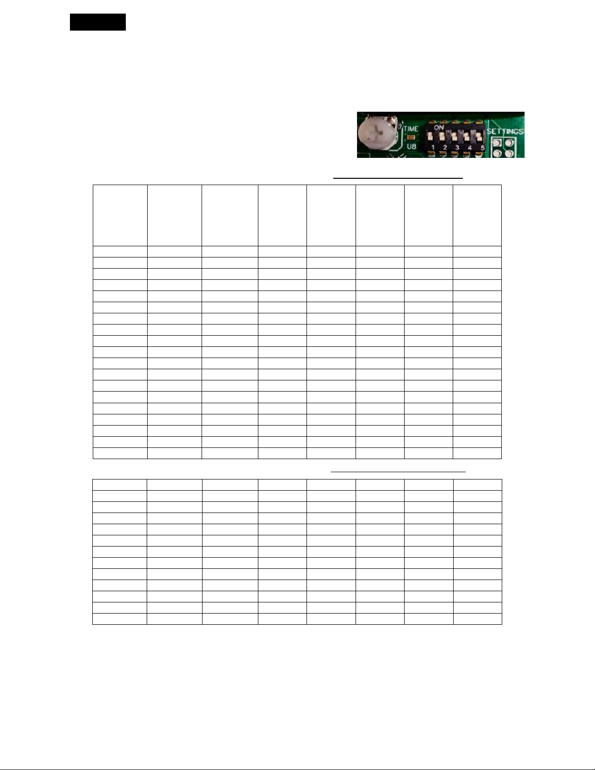
8. Set up switches and observation time dial as indicated in the chart and
diagram later on in this document or the back of the cover of the enclosure.
These switches and dial are located on the control board.
9. Re-install the cover of the control partition inside the enclosure by
reinstalling the screws removed previously and tightening them until snug. Be
sure not to pinch any wires or strip the screws.
10. Install electrical lines from the supply breaker for the controlled device to
the marked LINE SIDE of the contactor and bonding/ground attachment.
Ensure proper torquing of wires.
11. Install electrical lines from end device to be controlled (ie: EV charger) to
LOAD SIDE of contactor and bonding/ground as required by local electrical
codes. Ensure proper torquing of wires.
12. When safe, energize the device and check the control board for the red
light to be on indicating power and the green output light is not flashing. If the
green light is flashing continuously, it indicates that there is little to no current
being read by one or both of the current monitoring devices. Most operating
installations should have some current flow on both main lines so this may
indicate improper installation of one or both of the current monitoring
devices. The green LED will stop flashing when it senses some current on both
main lines. Although it will still operate with one current monitoring device
not reading current the installation should be verified. To do this, turn on a
high current 240V device in the electrical system and the LED should stop
flashing. If it does not recheck the current monitoring device installation from
step 3 ensuring that the polarity of the current monitoring devices is correct
and all connections are secure. If this is all correct, contact the manufacturer.

IENGLISHI
9
13. Install enclosure cover and when safe to do so, energize the system.
(Note: The contactor may not close until a computational observation time of
between 0 - 10 minutes. The algorithm must be satisfied the system will
remain below 80% of the rated main breaker and other values included in it.
This is partially dependent on the setting of the timer adjustment screw
(white) on the control board. If this observation time is too long, it can be
adjusted by turning this dial setting counter-clockwise but this should not be
set below 1 minute to avoid undesired operation.)
SETTINGS CHARTS
See the setting diagram chart on the next page and continued instructions
Consult the inside cover of the device for settings. There you will find the setting
applies to the device model and iteration you have. Only use the setting
appropriate for the model of the device. For example, the settings for an
EVEMS240-100 are for electrical service sizes of 100A and under. While the
settings for EVEMS240-200 are for service sizes of 125A and over. The chart
provided here is for reference only and may differ from the generation you are
using.

IENGLISHI
10
* All settings are applicable for EV chargers or other loads that tolerate switching their power off
when required.
Red LED: Power Green LED: Output
White Dial Time Setting: 0-10 min.
(Location of Dial and Switches may vary)
Below Settings are for Main Breakers Rated at 80% Continuous Load Only
Below Settings are for Main Breakers Rated at 100% Continuous Load Only
Main
Electrical
Service
Monitored
Breaker Size
End Device
Controlled
Max Current
Draw
EV Charger
Suggested
Breaker Size
For 80% Load
DIP
Switch
1
DIP
Switch 2
DIP
Switch 3
DIP
Switch
4
DIP
Switch 5
60
20
25
OFF
OFF
OFF
OFF
OFF
60
24
30
OFF
OFF
OFF
OFF
ON
70
20
25
OFF
OFF
OFF
ON
OFF
70
24
30
OFF
OFF
OFF
ON
ON
90
30/32
40
OFF
OFF
ON
OFF
OFF
90
40
50
OFF
OFF
ON
OFF
ON
100
24
30
OFF
OFF
ON
ON
OFF
100
30/32
40
OFF
OFF
ON
ON
ON
100
40
50
OFF
ON
OFF
OFF
OFF
100
48/50
60
OFF
ON
OFF
OFF
ON
125
30/32
40
OFF
ON
OFF
ON
OFF
125
40
50
OFF
ON
OFF
ON
ON
125
48/50
60
OFF
ON
ON
OFF
OFF
150
30/32
40
OFF
ON
ON
OFF
ON
150
40
50
OFF
ON
ON
ON
OFF
150
48/50
60
OFF
ON
ON
ON
ON
200
30/32
40
ON
OFF
OFF
OFF
OFF
200
40
50
ON
OFF
OFF
OFF
ON
200
48/50
60
ON
OFF
OFF
ON
OFF
60
20
25
ON
OFF
OFF
ON
ON
60
24
30
ON
OFF
ON
OFF
OFF
100
30/32
40
ON
OFF
ON
OFF
ON
100
40
50
ON
OFF
ON
ON
OFF
100
48/50
60
ON
OFF
ON
ON
ON
125
30/32
40
ON
ON
OFF
OFF
OFF
125
40
50
ON
ON
OFF
OFF
ON
125
48/50
60
ON
ON
OFF
ON
OFF
150
40
40
ON
ON
OFF
ON
ON
150
48/50
50
ON
ON
ON
OFF
OFF
200
30/32
40
ON
ON
ON
OFF
ON
200
40
50
ON
ON
ON
ON
OFF
200
48/50
60
ON
ON
ON
ON
ON

IENGLISHI
11
STEP 4: TEST FOR OPERATION
Test device for correct operation.
Warning: Warranty VOID if any devices are installed incorrectly.
MAINTENANCE
Do not use any cleaning solvents on the devices.
Electrical connection must be inspected, maintained, and re-torqued every year
by qualified personnel to maintain safe and proper operation. The interval may
need to be decreased in areas with high ambient temperature variance.
TROUBLESHOOTING
Contactor does not close when the initial device is powered on:
There is an initial delay when the device is powered on while the computer
algorithm is checking the electrical service. The contactor will not close until a
computational observation time elapses between 0 - 10 minutes. During this time
the current draw on the main electrical service wires must remain below
threshold current values of 80% of the main breaker size. This is also dependent
on the setting of the timer adjustment screw (white) on the control board referred to
in step 8 and the chart in the instructions and other algorithmic values. If this
observation time is too long, it can be adjusted by turning this screw counter
clockwise. You can check for contactor operation by turning this adjustment all the
way counter clockwise and waiting for the current on both monitored main service
wires to drop below 80% of the main service breaker rating for a short time as
associated with the internal algorithm. The contractor should close shortly after this
happens. This adjustment screw must not be left in this position but should be set
no less than 1 minute to avoid contactor chattering and premature failure. If this test
shows the device is not working, then check for 240/208V power at the line side
terminations on the contactor. If there is power present, next check that both wire
connectors (stake-ons) on the terminals that are plugged into the line side of the

IENGLISHI
12
contactor are secure. Once this is confirmed, then check that the wire connectors on
each side of the contactor coil are secure. If they are secure, next check the field-
installed wires in the contactor lugs on both the line side and load side are properly
installed and that voltage is present on the line side wires. Ensure the current
monitoring device connections are the correct polarity. Ensure the current
monitoring device wires and connectors are fully seated in the respective connector
and receptacles. If these items all have been checked and the issue is not resolved,
please de-energize and contact the manufacturer.
Improper operation of contactor:
Check if the length of the current monitoring device lead wires are coiled close to
other 120/240V lines and if so move them away from the area as this can cause
improper operation. Next check if the current monitoring devices are closed
securely. If they are, check if the current monitoring devices are installed in the
correct orientation with the arrow shown inside the current monitoring device eye
(window opening) pointing in the direction of the current flow. If the orientation is
correct, then verify that both service wires are consistently well below the
operational current specifications for up to 15 minutes (depending on the setting of
timer adjustment) with an amp meter. Ensure the current monitoring device
connections are the correct polarity (while plugged into the control board the red
wire should closest to the partition side wall on each plug). Ensure the current
monitoring device wires and connectors are fully seated in the respective connector
and receptacles.
If the green LED is flashing it indicates there has been no current recorded on one or
both current monitoring devices for some time. Turning on an electrical load should
cause this to stop flashing in less than a minute. If that does not happen check for
improper current monitoring installation and test again. If all these items are verified
and improper operation still exists, please de-energize the device and contact the
manufacturer.
Contactor chatters on and off or makes loud humming noise:
Check for approximately 240V between coil terminals when the contactor is closed. If
this is below 200V check the voltage on the line side of the contactor to ensure rated
system voltage is available. (It should be above 204V) Check for the same steady
voltage on the load side of the contactor when the contacts are closed. If voltage is

IENGLISHI
13
good at all locations, then the most common cause of an abnormally noisy
contractor that is still operating normally is dust or other particles in the active part
of the contactor. The contactors can be disassembled, and surfaces can be cleaned
to remedy this. Do not allow installation particles or dust particles to be blown
around the enclosure at installation and operate in a clean environment.
If the contractor is chattering on and off and the voltage at the load side of the
contactor is not steady, then verify that the timer adjustment screw (white) on the
control board is set approximately ½ way between the left and right rotation. If
adjustment is needed insert a screwdriver and adjust accordingly and reset power to
the device. The farther this is turned clockwise the more time the computer
algorithm will watch the service loading before allowing the load side (ie: EV charger)
to energize. Ensure the current monitoring device connections are the correct
polarity (red wire closest to the plastic partition when it is plugged into the socket).
Ensure the current monitoring device wires and connectors are fully seated in the
respective connector and socket. If this is completed and the contractor is still
chattering or making a loud noise, please de-energize the device and contact the
manufacturer.
The device is built with noise isolators between the contactor and the enclosure. If
the screws that attach the contactor to the enclosure are overtightened or removed
any sound may be amplified. These screws can be adjusted to allow for acoustic
separation while maintaining the connection between the enclosure and contactor
chassis.

IENGLISHI
14
INFORMATION
This document contains important instructions
which must be followed during the
installation, maintenance of this device.
Notes
After installation verify that the device is
securely attached to an adequate structure in a
well
-ventilated location.
It is the installer’s responsibility to verify that
the electric power source is adequate for the
use of the device.
Do not use any solv
ents to clean this device.
Do not paint or apply exterior finishing to this
device.
Do not use this energy management system
with end devices that require constant power.
Cautions
The installation of the device must be done to
the latest electrical code
requirements and
with the consultation of, and according to the
manufacturer’s specification and guidelines of
both the Electrical Vehicle (EV) and the
Charging Station. This device will shut off and
re
-energize electricity to both the Electric
Vehicle, i
ts Charging Station, or other load-side
devices without notice.
Warning
Read all documentation provided by the
device manufacturer before using this product
and follow the installation and setup
procedures. Always disconnect any and all
sources of power before starting work.
Do not modify, repair, or dismantle the
device.
Neve
r introduce water or any other liquids
to the area around or on this device.
Do not install the device near flammable
materials, explosives or fuels, chemical
products, and vapors.
Do not install this device in a hazardous or
wet environment or location
D
isconnect this device immediately if
defective or damaged in any way and
contact the manufacturer.
Any improper use of the device could result
in serious injuries, death, or damage to
property.
Any improper use of the device can cause
damage which will v
oid the warranty.
Never use the device above or below the
temperature range of 34°F to 104°F (1°C to
40°C). The devices must be always kept
free of frost and water vapor.
Feedback
We are always happy to hear your feedback
and we look forward to hearing from you.
Please email all comments to
customerservice@blackbox
-in.com.
You can also contact us by clicking on the
message us button on our website at
www.blackbox
-in.com.

IENGLISHI
15
Limited warranty
1.
Black Box Innovations Inc. warranties this
device against any defects for a period of one
year from the date of shipping. The warranty
is limited to the components and equipment
supplied by
Black Box Innovations Inc.
2.
Black Box Innovations Inc. may undertake
repair or replacement, at the site or the
manufacturing location, at its option, of the
defective material only after an evaluation
has been made by its representative.
3.
If, in the opinion of Black Box Innovations
Inc. installation has been done incorrectly, or
the device is used inappropriately, or repairs
have been done by unauthorized personnel
other than representatives of Black Box
Innovations Inc., the warranty will be
automatically void.
4.
Black Box Innovations Inc. will not be held
liable for damages or delays and will not be
required to pay the transport cost of the
charge controller claimed to be defective.
5.
Prior written consent must be made by
Black Box Innovations Inc. before repairs,
replacement, modifications, or
compensation is to be made.
6.
Black Box Innovations Inc. shall not be
liable for any indirect damages or delays
caused by inadequate workmanship, or
materials on devices install. This also applies
if the installations are not
made in
accordance with the manufacturer’s
instruction, local electrical codes, as well as
specifications of devices powered thru this
device.
7. Black Box Innovations Inc. shall not be
liable for any direct or indirect damages or
delays for any devices tha
t are connected
to this device that can not tolerate having
supplied power switched off for any time
period specified by the device or when the
device is in need of repair or maintenance.
8.
A
ny device or accessory supplied with this
device to be installed or connected remotely
from the charge controller will be
guaranteed by the manufacturer only under
the conditions mentioned in paragraphs 6 &
7 and in accord with the rest of this
document.
9.
Any repairs made at the Black Box
Innovations Inc. factory are warrantied for
30 days from the date of repairs.
10.
Any components supplied for repairs are
warrantied for the remaining of the
warranty on the original product or 90 days
whichever is longer.
This manual suits for next models
1
Table of contents
Popular Industrial Equipment manuals by other brands

ABB
ABB HT573826 Operation manual

Festo
Festo EPCO-KF Series Appendix to the operating instructions

ABB
ABB XAC17976 original operation manual

INOXPA
INOXPA SLR Ex Installation, service and maintenance instructions

Schmidt
Schmidt TorquePress 520 Original assembly instructions

Jäger
Jäger Z62-D360.13 S5A manual

Dialight
Dialight Medium Intensity Quick start manual

technotrans
technotrans manroland beta.d 40 Original instruction manual

schmersal
schmersal AZM201Z-I2-SK-T-1P2PW-A-DU Instructions for operation

Eaton
Eaton NZM1-XDTV Series Instruction leaflet

ABB
ABB HT842115 Operation manual

Mira
Mira CR4000 Operational Instruction Manual