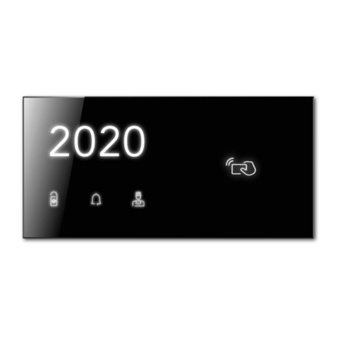
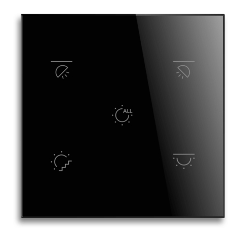
Black Nova AXES Spark User manual

AXES Keypads (Spark)
User Manual
All Rights Reserved - BLACK NOVA ITALIA S.R.L. - 2022
A Tribute to Minimalist Aesthetics of the 20th Century. Its natural elegance elicits straight lines, simple shapes, vivid colors and
perfect glass surfaces are a stylish match for any interiors.
Its bespoke look and precise performance create an experience of pure comfort and aesthetic pleasure. The AXES
Hospitality collection is available in different control congurations also with RFID card reader.
GRAND HOTEL
MILANO

AXES SPARK Keypad Panels Manual V1.1
Page 1 of 21
Index
Important Notes ......................................................................................................................................................... 2
Legal Principles ....................................................................................................................................................... 2
Scope of Applicability ........................................................................................................................................... 2
Safety information...................................................................................................................................................... 3
Important Information............................................................................................................................................ 3
Please note ............................................................................................................................................................. 3
Safety precautions ................................................................................................................................................. 4
Introduction ................................................................................................................................................................ 5
Included in the box.................................................................................................................................................... 6
Back End box .......................................................................................................................................................... 6
Front End box .......................................................................................................................................................... 6
Maintenance.............................................................................................................................................................. 6
Cleaning...................................................................................................................................................................... 6
Installation ................................................................................................................................................................... 7
Keypad panel front side ........................................................................................................................................ 7
Keypad panel back side....................................................................................................................................... 9
Wiring specifications .............................................................................................................................................. 9
Connection diagrams.......................................................................................................................................... 11
Required back box types .................................................................................................................................... 16
Back box installation ............................................................................................................................................ 16
Keypad installation............................................................................................................................................... 17
Programming the keypad....................................................................................................................................... 18
FAQ ............................................................................................................................................................................ 19
Glossary ..................................................................................................................................................................... 20
Warranty exclusion................................................................................................................................................... 21

AXES SPARK Keypad Panels Manual V1.1
Page 2 of 21
Important Notes
To ensure fast installation and start-up of the units, we strongly recommend that the following information
and explanations are carefully read and adhered to.
Legal Principles
Subject to Change
Black Nova reserves the right to make any alterations or modifications that serve to increase the efficiency
of technical progress. Black Nova owns all rights arising from the granting of patents or from the legal
protection of utility patents. Third-party products are always mentioned without any reference to patent
rights. Thus, the existence of such rights cannot be excluded.
Copyright
This documentation, including all figures and illustrations contained therein, is subject to copyright
protection. Any use of this documentation that infringes upon the copyright provisions stipulated herein is
prohibited. Reproduction, translation, electronic and photo technical filing/archiving (e.g. photocopying),
as well as any amendments require the written consent of Black Nova. Non-observance will entail the right
of claims for damages.
Personnel Qualification
The use of the product described in this document is exclusively geared to specialists having qualifications
in Black Nova System programming, electrical specialists or persons instructed by electrical specialists who
are also familiar with the appropriate current standards. Black Nova assumes no liability resulting from
improper action and damage to Black Nova products and third-party products due to non- observance
of the information contained in this document.
Intended Use
For each individual application, the components are supplied from the factory with a dedicated hardware
and software configuration. Modifications are only admitted within the framework of the possibilities
documented in this document. All other changes to the hardware and/or software and the non-
conforming use of the components entail the exclusion of liability on part of Black Nova.
Please send your requests for modified and new hardware or software configurations directly to Black
Nova
Scope of Applicability
This application note is based on the stated hardware and software from the specific manufacturer, as
well as the associated documentation. This application note is therefore only valid for the described
installation. New hardware and software versions may need to be handled differently.
Please note the detailed description in the specific manuals.

AXES SPARK Keypad Panels Manual V1.1
Page 3 of 21
Safety information
Important Information
Read these instructions carefully before trying to install, configure, or operate products.
The following special messages may appear throughout this bulletin or on the equipment to warn of
potential hazards or to call attention to information that clarifies or simplifies a procedure.
This is the safety alert symbol. It is used to alert you to potential personal injury hazards. Obey
all safety messages that follow this symbol to avoid possible injury or death.
The addition of either symbol to a “Danger” or “Warning” safety label indicates that an
electrical hazard exists which will result in personal injury if the instructions are not followed.
DANGER
DANGER indicates an imminently hazardous situation which, if not avoided, will result in death or serious
injury.
WARNING
WARNING indicates a potentially hazardous situation which, if not avoided, can result in death or serious
injury.
CAUTION
CAUTION indicates a potentially hazardous situation which, if not avoided, can result in minor or
moderate injury.
NOTICE
NOTICE is used to address practices not related to physical injury. The safety alert symbol shall not be
used with this signal word.
Please note
Electrical equipment should be installed, operated, serviced, and maintained only by qualified personnel.
No responsibility is assumed by Black Nova for any consequences arising out of the use of this material.
A qualified person is one who has skills and knowledge related to the construction, installation, and
operation of electrical equipment and has received safety training to recognize and avoid the hazards
involved.

AXES SPARK Keypad Panels Manual V1.1
Page 4 of 21
Safety precautions
WARNING
HAZARD OF INCORRECT INFORMATION
Do not incorrectly configure the product, as this can lead to incorrect reports and/or data results.
Do not base your maintenance or service actions solely on messages and information displayed by the
software.
Do not rely solely on software messages and reports to determine if the system is functioning correctly or
meeting all applicable standards and requirements.
Consider the implications of unanticipated transmission delays or failures of communications links.
Failure to follow these instructions can result in death, serious injury, or equipment damage.
The information provided in this documentation contains general descriptions and/or technical
characteristics of the performance of the products contained herein. This documentation is not intended
as a substitute for and is not to be used for determining suitability or reliability of these products for specific
user applications. It is the duty of any such user or integrator to perform the appropriate and complete risk
analysis, evaluation and testing of the products with respect to the relevant specific application or use
thereof.
Neither Black Nova nor any of its affiliates or subsidiaries shall be responsible or liable for misuse of the
information that is contained herein.
If you have any suggestions for improvements or amendments or have found errors in this publication,
please notify us.
All pertinent state, regional, and local safety regulations must be observed when installing and using this
product.
For reasons of safety and to help ensure compliance with documented system data, only the
manufacturer should perform repairs to components.
When devices are used for applications with technical safety requirements, the relevant instructions must
be followed.
Failure to use Black Nova product may result in injury, harm, or improper operating results.
Failure to observe this information can result in injury or equipment damage.
No part of this document may be reproduced in any form or by any means, electronic or mechanical,
including photocopying, without express written permission of Black Nova.

AXES SPARK Keypad Panels Manual V1.1
Page 5 of 21
Introduction
The AXES® Collection
A Tribute to Minimalist Aesthetics of the 20th Century.
A Tribute to Minimalist Aesthetics of the 20th Century. Its natural elegance elicits straight lines, simple
shapes, vivid colors and perfect glass surfaces are a stylish match for any interiors. Its bespoke look and
precise performance create an experience of pure comfort and aesthetic pleasure. The AXES collection
is available in different control configurations also with RFID card reader.
This manual describes how to install, configure and take full advantage of all the available functions.

AXES SPARK Keypad Panels Manual V1.1
Page 6 of 21
Back End box
1. AXES Back End
Front End box
1. Support Frame Protection Cover
2. Support Frame (BN) (quantity according to the Front End size)
3. Spacer for Socket Frame (quantity according to the Front End type and size)
4.
a. Single-Conductor wire connectors: WAGO 243-211 and WAGO 243-212
b. Multi-Conductor wire connectors: 2 pcs15EDGK-5.08-2P connector
5. Machine Screws (quantity according to the Front End size)
6. Plastite® Screws (quantity according to the Front End size)
7. Pre-installation manual (available for download from Black Nova Partner Portal)
Please check the contents of the box immediately after unpacking the device.
Maintenance
The keypad panel is maintenance-free. The device cannot be renovated or repaired to extend its life.
In case of any damage please contact the Customer Care service.
Cleaning
Dirty keypads may be cleaned with a dry cloth. Corrosive cleaning agents or solvents must never be used
to clean the push button panels as these chemical products can affect and impair the function.

AXES SPARK Keypad Panels Manual V1.1
Page 7 of 21
Installation
Keypad panel front side
Please refer to the following pictures to identify the touch panel’s buttons and indicators.
Card Holder with/without RFID reader
DHBECRC / DHBECHC
RFID reader
DHBEDRC
Numeric Keypad
DHBENK*
Outdoor Panel with Small Number
DHBEN1* (Product Preview)
Outdoor Panel with Small Number
and Indicator
DHBEN1* (Product Preview)
Outdoor Panel with XL Number
DHBEN3*
The Keypads Back End can be assembled with Double Frames Front Ends to achieve the following result
(example)

AXES SPARK Keypad Panels Manual V1.1
Page 8 of 21
Keypad panel back side
Connections and operating elements
1 –24V Power supply connector
2 –Status LED
3 –Service button
4 –Cresnet® communication bus
5 –Temperature and Humidity Sensor
Keypad panel wiring
The Spark bus wiring is done according to the following drawings:
15EDGK-5.08-2P
15EDGK-5.08-2P
WAGO 243-211
WAGO 243-212
OR
Multi-Conductor wire connectors
e.g., crestron cable
Single-Conductor wire connectors
e.g., knx cable, cat 5 or above
The WAGO 243-212 (White/Yellow) terminal, carrying the RS485
communication must be plugged into the connector “A” and the
WAGO 243-211 (Black/Red), carrying the 24V power supply, into the
connector “B” as shown at side.
Cable for application must be calculated according to length and
quantity of panels of the branch.
WARNING
●Do not connect the power supply cable to RS485 line
●Always test the cable polarity before connecting

AXES SPARK Keypad Panels Manual V1.1
Page 9 of 21
Wiring specifications
Communication bus wiring
The communication bus wiring is done according to the following rules:
1. Communication cable must be a twisted pair type cable: UTP CAT 5 or above
2. Daisy-chain topology: maximum extension of the wire (twisted pair cable for data) should not
exceed 300 meters. Line termination on the last keypad is required (resistor 120Ω).
3. Star topology: maximum extension of the wire (twisted pair cable for data) should not exceed 100
meter and the total length of all branches should not exceed 300 meters.
4. The GND wire should be always connected to all keypads and the Nova Hub, even if some keypads
are powered by different power supplies.
# Keypads
on the
project
Topology
Recommended
Branch
Quantity
Branch
Termination
required
Max cable
length for each
branch
Max Total
cable length
1..64
Daisy-chain
1
Yes
300m
300m
1..64
Star
≥2
No
100m
300m
Power line wiring
The following rules are critical for correct installation:
1. Refer to the keypad datasheet for details on power consumption.
2. A connection between the GND terminal of all keypads and the GND terminal of the Nova Hub is
required even in installation where additional power supplies are present.
3. Maximum permissible voltage drop between the power supply (24 V) and keypad is 4V.
4. Current carrying capacity and voltage drop depend on type of cables and their length (below
table).
Wire size, mm2
Max Resistance /100m, Ohm
# Keypads on
the project
Max distance of the
last keypad from the
power supply
0.205 mm2
8.42 Ohm
0.325 mm2
5.30 Ohm
0.820 mm2
2.10 Ohm
1.04 mm2
1.66 Ohm
1.65 mm2
1.05 Ohm
1
155 m
X
246 m
X
300 m
X
X
X
2
78 m
X
123 m
X
300 m
X
X
X
4
39 m
X
62 m
X
155 m
X
197 m
X
300 m
X
8
19 m
X
31 m
X
78 m
X
98 m
X
156 m
X
16
10 m
X
15 m
X
39 m
X
49 m
X
78 m
X
32
5 m
X
8 m
X
19 m
X
25 m
X
39 m
X
48
3 m
X
5 m
X
13 m
X
16 m
X
26 m
X
64
2 m
X

AXES SPARK Keypad Panels Manual V1.1
Page 10 of 21
4 m
X
10 m
X
12 m
X
20 m
X
DISCLAIMER
Characteristic of cables varies by manufacturer, environmental condition and other factors. The
values given in the table below are for reference purposes only, and does not substitute for professional
measurement on field.

AXES SPARK Keypad Panels Manual V1.1
Page 11 of 21
Connection diagrams
Daisy chain connection diagrams
Example 1 –Using a twisted pair cable for power line
Attention: the lengths must comply the wiring specifications described in the previous chapter.
Example 2 –Using single core cables for power line
Attention: the lengths must comply the wiring specifications described in the previous chapter.

AXES SPARK Keypad Panels Manual V1.1
Page 12 of 21
Example 3 –Using an external power supply for power line
Attention: the lengths must comply the wiring specifications described in the previous chapter.

AXES SPARK Keypad Panels Manual V1.1
Page 13 of 21
Start topology connection diagrams
Example 1 –Using a twisted pair cable for power line
Attention: the lengths must comply the wiring specifications described in the previous chapter.

AXES SPARK Keypad Panels Manual V1.1
Page 14 of 21
Example 2 –Using single core cables for power line
Attention: the lengths must comply the wiring specifications described in the previous chapter.
Example 3 –Using an external power supply for power line
Attention: the lengths must comply the wiring specifications described in the previous chapter.

AXES SPARK Keypad Panels Manual V1.1
Page 15 of 21
Example 4 –Mixing main and external power supply for power line
Attention: the lengths must comply the wiring specifications described in the previous chapter.

AXES SPARK Keypad Panels Manual V1.1
Page 16 of 21
Required back box types
UK 3x3 Standard Back Box (mm)
FR Dry Lining Steel Back Box (mm)
EU 2M Standard Back Box (mm)
Please note:
• Back box depth must comply with specific installed socket (shaver, ethernet plug, phone plug,
USB ports, etc.)
• Only Back Box 1a and 1b supports the Socket Frame
• Use Plastite® screw with Back Box type 1c
Back box installation
Wall cut out dimensions may vary depending on the back box manufacturer. For exact cut out dimensions
please refer to the manufacturer of the back box.
Single frame
Double frame
Regardless of the back box type, the center distance between two back boxes is always 97.5 mm
WALL
Back box
cut out
WALL
97.5mm
Back box
cut out
Back box
cut out

AXES SPARK Keypad Panels Manual V1.1
Page 17 of 21
Keypad installation
Step 1 –Mount (2) on (1) using (3)
Step 2 –Insert (4) in (2)
Single Frame
1a, 1b, 1c –Back Box
2 –Support Frame (BN)
3 –Screws
4 –AXES Keypad
Double Frame
1a, 1b, 1c –Back Box
2 –Support Frame (BN)
3 –Screws
4 –AXES Keypad
WALL FLUSH INSTALLATION NOTE
When the keypads are mounted with TRUFIG and WALLSMART accessory for wall flush, follow their
instructions, disable the sensors on board and use external sensors.
2
3
4
2
1a
1b 1c

AXES SPARK Keypad Panels Manual V1.1
Page 18 of 21
Programming the keypad
The SPARK keypad panel version can be installed together with a Nova Hub Gateway in a Control4, Lutron
environment; please refer to the dedicated manual to configure the keypad.

AXES SPARK Keypad Panels Manual V1.1
Page 19 of 21
FAQ
Problem
Suggested solution
Keypad panel is not turning on
Check the power supply voltage and the polarity of power connection
Keypad panel is connected to the network
but does not represent any activity
•Check that the cable connector is clean and not damaged
•Check the cable termination pinout and polarity
•Check the integrity of the cable
•Check the keypad panel configuration
•Check that keypad panel has the proper address configured
•Check that keypad panel received configuration from the network
•Check that other devices in the network are not making the short circuit on
the bus
Buttons are not working immediately after
power up of the keypad panel
Wait until keypad panel application will start
The buttons sound is audible, but the LEDs
are not indicating any event
Check the LEDs configuration
Only part of keypad panel buttons is
working properly
Check the buttons configuration
Table of contents
Other Black Nova Keypad manuals
Popular Keypad manuals by other brands

Yale
Yale Smart Living EF-KP quick start guide
Sebury
Sebury K2 manual
RIDGE RESKEY
RIDGE RESKEY 14-RK10 quick start guide

UTC Fire and Security
UTC Fire and Security interlogix QS1500 installation instructions
Analog way
Analog way Smart Fade RK251 user manual

Radionics
Radionics D223 installation instructions
