Black Series HQ21 User manual

owner's
Bla Series
Mu
19501 E. Walnut Dr South City of Industry,CA 91748 USA
ADDRESS:
WEBSITE:
www.blackseries.net
TEL:
(833) 822-6737
YOUTUBE:
https://www.youtube.com/@BlackSeriesUS
AFTER-SALE
BLACK SERIES AFTER-SALES EMAIL :
BLACK SERIES AFTER-SALE DECLARATION OFFICIAL CLAIM LINK :
https://share.hsforms.com/1_yLZReNORy-V088QQThxZA3dkuv
(Including accessories introduction, trailer explanation)

Tle
of
Contents
Chapter IV Safe Operation of Vehicle Vehicle Hazard Management Inspection
Rules for Vehicle Operational Safety 37
I. Unsuitable tractors 38
II. Speeding 38
III. Towing Devices of Trailer and Tractor Must Be Properly and Firmly Connected 38
IV. Brakes 40
V. Trailer Light (and Brake) Controller 41
VI. Proper Use and Maintenance of Tires 41
VII. Correct Tightening Torque of Hub Nut Is Critical to Driving Safety 42
VIII. Overloading Prohibited 43
IX. Properly Distribute Load When Loading the Trailer 43
X. Towing Frame of Trailer is Crucial to Driving Safety 44
XI. Test Working State of Electric Brakes and Trailer’s Signal Lights before Driving 44
XII. Hazards of Modifications to Trailer 44
XIII. Precautions for Generator 44
XIV. Dangerous Gas Equipment 45
XV. Guide on Safe Trailer Towing 45
XVI. Check Trailer Every Time Before Towing and During Towing 46
XVII. Campground Requirements 47
XVIII. Fire and Safety 47
I. Technical Parameters of Camper Trailer 12
II. Structure Composition and Features 13
Chapter III Vehicle Operating Instructions 16
Chapter II Vehicle Structure and Components 11
Chapter I Introduction 05
I. Operating Instructions of Circuit System 16
4. DC and AC outlet circuits 26
5. Water level display circuit 27
6. Electromagnetic brake circuit 28
7. Andersen charging circuit 28
8. PV charging circuit 28
3. Switches of interior lights and strip lights and switches of exterior front, rear, left and right lights 25
161. Operating instructions of main control panel
19
2. Operating instructions of on board appliances
II. Operating Instructions of Water System 29
III. Operating Instructions of Gas System 32
IV. Operating Instructions of Fuel System 34
V. Operating Instructions of Awning 35
VI. Operating Instructions of Electric Step 35
VII. Operating Instructions of Stabilizer Legs and Guide Wheels 35
4. Operating instructions for electric toilet 30
5. Water tanks 31
3. Operating instructions for shower devices 30
291. Water filling of drinking water tank and purified water tank
30
2. Operating instructions of outdoor stove

XXXVIII. Sewage System 63
XXXIX. Water Tank Maintenance 64
XXXX. Extension Space System 65
XXXXI. Operation, Equipment and Safety of Multi-Purpose Sports Trailer 66
I. Panels 50
II. Water Heater Access Panel 50
III. Fridge Access Panel 50
IV. Vents 51
V. Roof Vent 51
VI. Exterior Lights 51
VII. Door 51
VIII. Windows 52
IX. Emergency Exit Window 52
X. Acrylic Window 52
XI. Awning 53
XII. Extension 53
XIII. External Washing Facility 53
XIV. Access Step 53
XV. Bathroom 53
XVI. Toilet 53
XVII. Arc Sofa 54
XVIII. Sofa/Bed Conversion 54
XIX. Free-Standing Furniture 54
XX. Mini Louvers 54
XXI. Foldable Divider 54
XXII. Foldable Bed 55
XXIII. Electrical System 55
XXIV. Battery and Compartments 55
XXV. System Monitoring Panel 56
XXVI. Internal Fuse Panel/Fuse 57
XXVII. Interior Lights 57
XXVIII. HDTV Antenna on Roof 57
XXIX. LCD TV 58
XXX. External Speakers 58
XXXI. AC System 58
XXXII. Power Distribution Center 58
XXXIII. Ground-Fault Circuit Interrupter 59
XXXIV. Generator 59
XXXV. Power VS Altitude 61
XXXVI. Gas System 61
XXXVII. Shower 63
I. Upkeep and Maintenance of Exterior and Auxiliary Components 72
II. Interior Maintenance 73
III. Upkeep and Maintenance of Tent 74
IV. Anti-Freeze Upkeep and Maintenance 75
V. The following mandatory upkeep items must be implemented by Black Series Camper 4S stores or
professional upkeep or maintenance service providers to guarantee the travel safety 77
VI. Effects of Long-Term Stay and Upkeep & Maintenance 81
Chapter VI Upkeep and Maintenance 71
Chapter VII Environmental Protection 84
Chapter VIII Accompanying Documentation 85
Chapter IX After-Sales Services 86
Chapter V Camper Trailer Equipment and Facilities 49

CHAPTER I INTRODUCTION 6
elcome
W
We are confident to give you exciting off-road camping
adventures and lasting and worthy memories.
We provide safe and reliable vehicles and manufacture
high quality products to meet your needs.
Reading this manual is one of the best ways to enhance your
enjoyment of your Black Series camper trailer.
This information will help you learn how to use all the features
of your new travel trailer.
A Black Series trailer is undoubtedly a smart investment.
Thank you for choosing Black Series.
Congratulations and welcome to the big family of
Black Series camper trailer owners.
CHAPTER I
INTRODUCTION

CHAPTER I INTRODUCTION
7CHAPTER I INTRODUCTION 8
WARNING
Warning - if the warning message is ignored,
there is a risk of serious personal injury or death.
DANGER
Danger - If the danger message is ignored,
there is an immediate danger of serious
personal injury or death.
CAUTION
Caution - the operation may cause damage to
the trailer or other properties.
ALERT
Alert - if the alert message is ignored, there
is a risk of minor or moderate injury.
This manual covers all Black Series camper/trailer models. The equipment and functions described in this manual may
not fit your trailer model, since some equipment and functions are optional or the equipment on your trailer is upgraded,
updated or iterated so rapidly that it may not be described in this manual. For the latest product information and updates,
please contact our after-sales services and local Black Series dealers. Subsequent modifications may be evident in the
actual products, and specifications are subject to change without notice.
1. UPDATES TO INFORMATION/PRODUCTS IN THIS MANUAL
Black Series offers limited repair and warranty scope specified in this manual for your trailers. Please carefully read this
manual and understand the warranty scope and your rights and responsibilities.
Please go to your dealer for any repair, upkeep or maintenance of your trailer. If you are close to the manufacturer, you
can return the trailer directly to the manufacturer’s 4S store for repair and upkeep or maintenance.
Maintaining your trailer in accordance with upkeep and maintenance tips and technical methods given in this manual will
give you a trouble-free camping experience. Regular maintenance will save you money in the long run. The service chart
on the back of this manual defines the minimum maintenance interval. The failure likelihood of important systems of your
trailer will be minimized by following this schedule.
The mandatory upkeep items required in this manual are crucial to your travel safety. The time spent on the inspection
and maintenance will ensure more years of good use of your trailer. Don’t forget that your trailer definitely needs and
loves daily maintenance on your own. Our After-Sales Service Department offers any help you need in daily maintenance
to ensure that you have access to technical support and original parts for repair and replacement. The replacement
components you need can be ordered from the After-Sales Service Department of Black Series.
2. WARRANTY, INSPECTION AND MAINTENANCE
User information contains important documents that explain the operations of the main appliances, systems and equipment
in your trailer. Since this manual does not cover all possible details of the devices and options installed on your trailer,
these instructional materials will help you operate, maintain and troubleshoot these devices and systems.
Depending on your trailer configuration and options applicable to electrical system, user information includes the following:
Owner’s Manual / fridge instructions / oven instructions / range hood instructions / microwave oven instructions / water heater
instructions / air conditioner instructions / generator instructions / water pump instructions / inverter instructions / smoke alarm
instructions / awning instructions / TV antenna instructions / stereo instructions / LCD TV instructions and other necessary
operating instructions.
Components of Black Series camper trailers are produced by different manufacturers. This manual is not exhaustive and does not
include all the details, and some items have separate instructions. This manual is for your information only. You can refer to
otherinstructions. If the instructions of a certain item is not available, please contact the customer services of Black Series.
3. USER INFORMATION
Black Series provides warranty services for all the processes and materials of our camper trailers and RVs within the
warranty period. During the warranty period, if any quality problem happened during the normal use and the trailer is
tested and determined to be a defective product by the Company, user is entitled to free repair or replacement.
(1) The warranty period starts from the date when the trailer is delivered to user.
(2) If any fault that happened in the warranty term is unable to be solved and is determined to be a product quality
problem by the service station, service station will offer field services free of charge.
(3) The Company does not authorize any organization or individual other than the service stations to perform QA tasks on the vehicle,
and is not responsible for all consequences arising from such. The Company promises to repair and maintain the vehicle, that is,
mainly repair the defects and faults of the vehicle during the warranty period, and replace damaged parts that cannot be repaired.
(4) The Company is not responsible for any non-vehicle repair costs and expenses incurred by faults covered in the warranty,
including but not limited to loss of income, loss of goods, road toll, insurance premium, operating profits, fines and other losses.
UNDER ANY OF THE FOLLOWING CIRCUMSTANCES, THE WARRANTY IS INVALID AND REPAIR AND MAINTENANCE
FEES WILL BE CHARGED AS IF THE WARRANTY PERIOD HAS EXPIRED.
(1) The warranty is only valid for the vehicle in normal use by the original buyer and should not be transferred or prolonged
in any way. Once the trailer is sold or otherwise disposed of by the original buyer to any third party, Black Series is no
longer resposible for anyone other than the original buyer.
5. WARRANTY TERMS
Although all trailers have been inspected thoroughly in the factory, it is the responsibility of dealers to fully inspect all trailer components
before shipment. This ensures that all components are in proper working condition and free of defects before delivery. During the
delivery, the dealer should help you inspect the interior and exterior of the trailer, instruct and explain how to properly use the trailer.
4. RESPONSIBILITIES OF DEALERS
However, it is your responsibility to fully understand how to use the trailer. To fulfill this responsibility, you must read all
instructional materials that accompanies the manual. If you don’t know how to use any appliance or device, you should
return to your dealer for further instructions.
Safety warning signs and symbols
This manual provides instructions for the operation and maintenance of your Black Series camper trailer. The instructions
in this manual must be followed to ensure the safety of personnel and the service life of the trailer.
Safety precautions to prevent injury or property damage must always be followed.
Safety information in this manual is marked with safety signs.
Risk levels are indicated by the following symbols:

CHAPTER I INTRODUCTION
9CHAPTER I INTRODUCTION 10
If your product has any quality problems, please contact us within seven days from the date of purchase and we will test the product
specifically. If the test results show that the product does have quality problems, After-Sales Service Department will replace the product
within fifteen business days.
I HAVE READ AND UNDERSTAND WARRANTY TERMS AND CONDITIONS.
7. RETURN AND EXCHANGE SERVICE
6. WARRANTY ITEMS AND PERIOD
(2) Warranty is invalid for trailers used for rental, loan or commercial purposes.
(3) Warranty is not valid for the trailers for auction, exhibition, refurbished and secondhand trailers.
(4) The warranty does not cover misuse in violation of the instructions, collisions, modifications to the design, and damage
in traffic accidents.
(5) During the warranty period, the Company has no warranty period if the upkeep and maintenance is not carried out in
accordance with the upkeep requirements of this manual at service providers authorized by the Company. The warranty is
subject to maintenance records issued by our authorized service providers.
(6) The Company is not be responsible for any quality problems caused by change or loss of quality performance of relevant
components of vehicle due to any modifications or additions to the vehicle that are not authorized by the Company, nor shall
the Company be responsible for any safety accidents caused by such modifications or additions.
(7) All warranty should be performed by Black Series or an authorized representative of Black Series, and individuals and
organizations should not repair or replace accessories without authorization.
(8) Unless otherwise specified in writing by Black Series, any transportation, accommodation, towing or recycling expenses
incurred by warranty claim should be borne by the buyer.
(9) Black Series is not responsible for any damage due to improper use, maintenance and storage of the product by the ser
without following the provisions in the Operating Instructions of the product and this manual;
(10) Black Series is not responsible for the damage caused by dismantlement and modifications by the user or any unauthorized person.
(11) Black Series is not responsible for the damage other than product defects, such as collision impact, burning damage,
scratches and falling off of any components caused by external factors.
(12) Black Series is not responsible for the damage to the vehicle caused by natural or environmental impact, such as: flood,
lightning, storm, hail and other force majeure.
(13) Black Series is not responsible for the normal noise, vibration, wear and aging of the vehicle.
(14) Black Series is not responsible for overloading and speeding of vehicle.
(15) Black Series is not responsible for faults due to use of parts or components not approved by the Company in the repair.
(16) Black Series is not responsible for damage that is caused in use of the trailer when the known or hidden fault is not
eliminated in a timely manner and resulting damage of other parts and components.
(17) Black Series is not responsible if the product name, model or number (or VIN code) on the warranty is inconsistent with
that of the product under warranty or is altered, and manufacture date of the vehicle is not available.
(18) Warranty does not cover any vehicle with a warranty period that has expired for 15 or more days.
Note: The Company reserves the right of final interpretation of the after-sales service terms.
CHARGEABLE BATTERY
TIRES
DOOR/WINDOW GLASS
APPLIANCES ON TRAILER
INVERTER
INTERIOR FURNITURE
ALUMINUM FRAME OF VEHICLE BODY
VEHICLE CHASSIS
6-MONTH WARRANTY
6-MONTH WARRANTY
6-MONTH WARRANTY
1-YEAR WARRANTY
1-YEAR WARRANTY
1-YEAR WARRANTY
15-YEAR WARRANTY
15-YEAR WARRANTY
VIN#
Name of Buyer:
Signature of Buyer:
Model L:
Warranty Year(s):
Date:

CHAPTER II VEHICLE STRUCTURE AND COMPONENTS 12
I. TECHNICAL PARAMETERS OF CAMPER TRAILER
CHAPTER II Product model
Dimensions (mm)
Front/rear
suspension (mm)
Wheel base (mm)
Rear wheel track (mm)
Approach
angle/departure angle (º)
Loaded weight (Kg)
Curb weight (Kg)
Tire specification
Tire quantity
Number of axles
HQ21
ARCDG6ZP03A
7998×2355×3110(mm)
-/2360
4700+883
1815/1815
-/23(°)
3485
3260
LT265/75 R16 10PR
4
2
HQ15
ZS2KH6X201B
7130×2400×2960(mm)
-/2503
4560
1840
-/21(°)
2850
2450
LT265/75 R16 10PR
2
1
Product model
Dimensions (mm)
Front/rear
suspension (mm)
Wheel base (mm)
Rear wheel track (mm)
Approach
angle/departure angle (º)
Loaded weight (Kg)
Curb weight (Kg)
Tire specification
Tire quantity
Number of axles
HQ19
ZS2KJ6X201G
7950×2403×3140(mm)
-/2330
4663+890
1830/1830
-/24(°)
3455
3055
LT265/75 R1610PR
4
2
HQ17
ZS77Z6YL01Z
7420×2340×3070(mm)
-/1973
4500+880
1830/1830
-/22(°)
3250
2865
LT265/75 R1610PR
4
2
HQ12
ARJ546W602G
5975×2410×2585(mm)
-/2305
3603
1840
-/21(°)
2600
2200
LT265/75 R1610PR
2
1
TH22
ZS4TP6XZ01L
8835×2500×3185(mm)
-/2930
5008+830
2110/2110
-/22(°)
3490
3390
LT235/75 R158PR
4
2
TH19
ARPF76ZP03T
7810×2425×3035(mm)
-/2535
4368+840
2000/2000
-/22(°)
3495
3095
LT235/75 R158PR
4
2
LJC
ARMEL6W602U
5995×2375×3000(mm)
982/1443
3570
1645
21.7/15(°)
4000
3510
185/75 R16C
6
2
D1
ARCDE6W602H
5880×2280×1620(mm)
-/2270
3543
1746
-/21(°)
2400
2125
LT265/75 R1610PR
2
1
F3
ARCDF6W6028
4700×1930×1495(mm)
-/1420
3213
1360
-/28(°)
1510
1255
LT235/75 R158PR
2
1
VEHICLE STRUCTURE
AND COMPONENTS
I. Technical Parameters of Camper Trailer
II. Structure Composition and Features
CHAPTER II VEHICLE STRUCTURE AND COMPONENTS
13 CHAPTER II VEHICLE STRUCTURE AND COMPONENTS 14
1. Chassis frame
2. Hubcap
3. Suspension
4. Base of towing device
5. Step assembly
6. Damper
(1) Chassis
Chassis of a lightweight trailer consists of chassis frame, tires, base of towing device, suspension, damper, etc. Galvanized
iron plates are riveted on the top side of chassis frame, wooden flooring is laid on the iron plates and chassis bottom is
sprayed with protective armor paint.
(2) Carriage
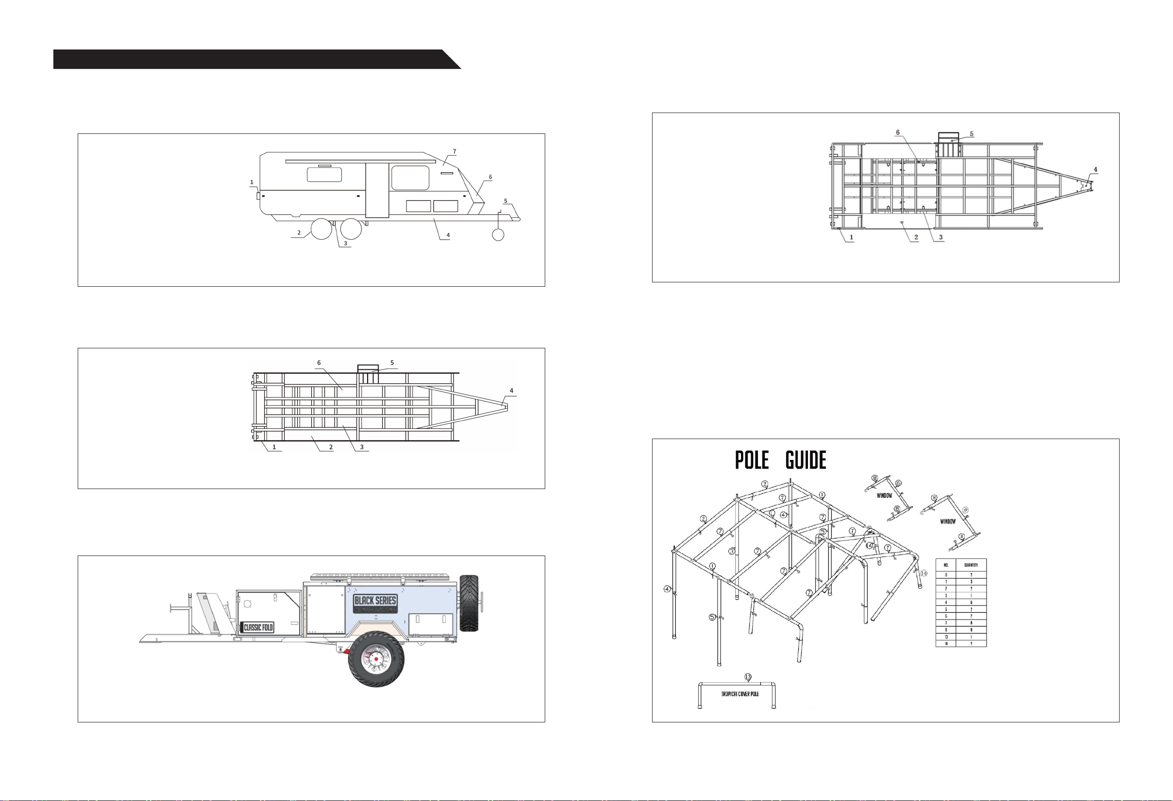
Carriage mainly consists of vehicle body frame, exterior body panels, access door, flap cover, tent, circular sofa, etc. A
foldable tent is installed in the carriage. When the flap cover is opened, the tent will be unfolded. Install the poles in place
according to the pole installation diagram (Fig. 2-5), stretch the telescopic poles, and the tent will be fully expanded. At this
moment, the installation of main tent is completed.
A side tent can be installed on the door side of carriage. The side tent consists of four parts: top, side enclosure, bottom
and a shower room. There are corresponding zippers on the main tent. Zip the top on the main tent first, and then side
enclosure, bottom and shower room, and install the poles on the corresponding positions according to the diagram. At this
moment, the installation of side tent is completed.
FIG. 2-3 OVERALL STRUCTURE OF CAMPER TRAILER
FIG. 2-4 CHASSIS COMPOSITION
FIG. 2-5 TENT POLE INSTALLATION DIAGRAM
1. Signal lights
2. Tire
3. Suspension
4. Chassis
5. Towing device
6. Gas cylinder compartment
7. Carriage
FIG. 2-1 OVERALL STRUCTURE OF CAMPER TRAILER
1. Chassis frame
2. Hubcap
3. Suspension
4. Base of towing device
5. Step assembly
6. Damper
FIG. 2-2 CHASSIS COMPOSITION
2.1 Hard-top camper trailer
A Black Series camper trailer mainly consists of chassis, carriage, traveling signal system, circuit system, water system, gas
system, fuel system, traction and brake devices, PV system, living system, etc.
Chassis of a camper trailer consists of chassis frame, tires, step assembly, base of towing device, suspension, damper, etc.
Waterproof wooden flooring is laid on the top side of the chassis frame, the space underneath the wooden floor is filled with
insulation material and chassis bottom is sprayed with protective armor paint.
II. STRUCTURE COMPOSITION AND FEATURES
2.2 Lightweight camper trailer
A lightweight camper trailer mainly consists of chassis, carriage, tent system, traveling signal system, circuit system, water
system, gas system, fuel system, traction and brake devices, solar system, living system, etc.

CHAPTER II VEHICLE STRUCTURE AND COMPONENTS
15 CHAPTER II VEHICLE STRUCTURE AND COMPONENTS 15
The carriage is equipped with a circular sofa and a portable dining table to provide a more comfortable space for customers.
And the dining table can be placed in the middle of the sofa, when the sofa is converted into a small bed, so that more people
can have a rest at the same time.
There is a portable fridge in the tool cabinet of the carriage for food storage. There is a stainless steel stove beneath the
sofa on the rear side of carriage. The stove can be pulled out from the outside. The stove is equipped with a gas stove, a
water basin and a faucet for is equipped with a gas stove, a water basin and a faucet for picnicking.
FIG. 2-6 PICTURE OF TENT
VEHICLE OPERATING
INSTRUCTIONS
CHAPTER III
I. Operating Instructions of Circuit System
II. Operating Instructions of Water System
III. Operating Instructions of Gas System
IV. Operating Instructions of Fuel System
V. Operating Instructions of Awning
VI. Operating Instructions of Electric Step
VII. Operating Instructions of Stabilizer Legs
and Guide Wheels

Circuit system of a camper trailer includes: signal light circuit; interior and external lighting circuits; on-board appliance circuits; alarm
circuit; electric step circuit; water level display circuit; electromagnetic brake circuit; DC and AC outlet circuits; Andersen charging
circuit; PV charging circuit; DC→AC inversion and AC→DC charging circuits.
Three charging systems (Andersen, PV and municipal power supply) that work in parallel ensure the battery pack of camper trailer is in
good working condition, and provide high quality uninterrupted power supply.
The operating principle of the circuit system is shown in diagram below.
1. OPERATING INSTRUCTIONS OF MAIN CONTROL PANEL
I. OPERATING INSTRUCTIONS OF CIRCUIT SYSTEM Switches of on-board appliance system are integrated on the main control panel on the vehicle and the corresponding
appliances are as follows:
(1) Water gauge (A) of the drinking water tank displays the current drinking water percentage of drinking water tank.
(2) Water gauge (B) of the purified water tank displays the current purified water percentage of purified water tank.
(3) Water gauge (C) of the gray water tank displays the current gray water percentage of the gray water tank.
(4) Water gauge (D) displays parameters such as current battery voltage, real-time current, real-time power, and accumulated
power consumption.
(5) The left 12V outlet circuit fuse (E) is disconnected when this branch is overloaded.
(6) The fridge circuit fuse (F) is disconnected when this branch is overloaded.
(7) If the main circuit fuse (G) is disconnected, all the branches except for water pump branch will not work.
(8) The right 12V outlet circuit fuse (H) is disconnected when this branch is overloaded.
(9) The radio circuit fuse (I) is disconnected when this branch is overloaded.
(10) The exterior light fuse (J) is disconnected when this branch is overloaded.
(11) The kitchen appliance circuit fuse (K) is disconnected when this branch is overloaded.
(12) The living room appliance circuit fuse (L) is disconnected when this branch is overloaded.
(13) The bedroom fuse (M) is disconnected when this branch is overloaded.
(14) Bathroom appliance circuit fuse (N) is disconnected when this branch is overloaded.
(15) The purified water pump circuit fuse (O) is disconnected when this branch is overloaded.
(16) The drinking water pump circuit fuse (P) is disconnected when this branch is overloaded.
(17) Water heater switches K1/K2.
(18) Inverter switch (K3). Turn on and off the inverter through switch K3 on the control board.
(19) Turn on and off the drinking water pump through the drinking water pump switch (K4).
(20) Turn on and off the purified water pump through the purified water pump switch (K5).
(21) Turn on and off the radio through the radio switch (K6).
(22) Turn on and off the fridge through the fridge switch (K7).
(23) 220V AC leakage protector (QF1): Switch on QF1 to energize the AC outlets on the interior branches when the municipal power
supply is accessible. AC power supply leakage protector QF1: In case of input of municipal power supply, switch on QF1, and air
conditioner, fridge and inverter are energized and work in AC→DC mode and battery is being charged; meanwhile, switch on QF2, and
AC outlets are energized through bypass function of inverter; switch off QF1, and municipal power supply is cut off.
Description: Main control switch fuse of the battery compartment should be closed.
(24) Inverter power supply leakage protector QF2: Switch on QF2 when the inverter is in the inversion (DC→AC) state, and
AC outlets on relevant interior branches are energized. To obtain AC 220V power supply in absence of municipal power
supply, close the inverter switch K3, switch on QF2, and inverter is working in DC→AC mode and all outlets on QF2 output
branches are energized; switch off QF2, and all outlets on QF2 output branches are de-energized.
Description: Inverter switch fuse of the battery compartment should be closed.
CHAPTER III VEHICLE OPERATING INSTRUCTIONS
17 CHAPTER III VEHICLE OPERATING INSTRUCTIONS 18
AIR CONDITIONER,
FRIDGE,
WATER HEATER
MUNICIPAL POWER
SUPPLY
CONTROL PANEL CD, FRIDGE, WATER
PUMP, WATER
HEATER
HOOD, EXHAUST FAN,
ELECTRONIC IGNITION, SMOKE
ALARM, WATER LEVEL DISPLAY,
AIR PARKING HEATER
MAIN CONTROL
SWITCH
INVERTER
CONTROL
INVERTER
POWER
SUPPLY
SOLAR
POWER CONTROLLER DC POWER SUPPLY
(STORAGE BATTERY)
LIGHTING
OF TRAILE
SIGNAL
LIGHTS OF
TRAILER
SIGNAL LIGHTS OF
TRACTOR
ELECTROMAGNETIC
BRAKE OF TRACTOR
ELECTROMAGNETIC
BRAKE FUSE SYSTEM
OF TRAILER
ELECTROMAGNETIC
BRAKE OF TRAILER
ANDERSEN POWER
SUPPLY OF TRACTOR
BAR COUNTER,
BEDROOM,
MICROWAVE OVEN,
LIVING ROOM, TV
FIG. 3-1 MAIN CONTROL PANEL

2.1 ENTERTAINMENT SYSTEM
A. Radio
Camper trailer has a car radio with a built-in CD cassette mechanism to play CDs, two interior Hi-Fi speakers and two exterior
waterproof speakers;
Operation of CD (BT610 BT202):
(1) First close the switch K4 on the control panel in Fig. 3-1;
(2) Long press the control knob for more than 3s to turn on the radio;
See radio instructions for specific functions.
Operation of CD (JSD520):
2. OPERATING INSTRUCTIONS OF ON-BOARD APPLIANCES
CHAPTER III VEHICLE OPERATING INSTRUCTIONS
19 CHAPTER III VEHICLE OPERATING INSTRUCTIONS 20
OPERATING INSTRUCTIONS
CONFIRM THE RADIO IS POWERED ON. THE FUNCTIONS OF BUTTONS ARE SHOWN BELOW:
Short press the button to turn on the radio; long press the button for 3s to turn off the radio.
1. POWER ON/OFF
Press this button repeatedly and LCD will display the functions in the following order: RADIO→USB→SD→AUX-IN→BT. In BT mode, short
press the button to end the call.
2. MODE--FUNCTION SELECTOR
In RADIO mode, short press the button to enter the browser; long press the button to automatically save radio stations.
In play mode, the function is to select songs.
3. AUTO SEEK SEARCH TUNING (AMS)
In RADIO mode, press the button to switch FM1-FM2-FM3 in the round-robin in each wave band.
In BT mode, short press the button to answer the call.
4. BAND BUTTON
In MP3 play mode, the function is to skip the tracks (USB/SD/MMC); press this button in the play to switch to the desired track. In RADIO
mode, the function is to search radio stations; press this button to search the desired radio station.
5/6. /BUTTON
Radio stations are stored 1-6, and press the button to broadcast. Play the music via external devices such as USB or SD/MMC card. In
the “play”, press the button to stop playing. Press the button again to continue playing.
7. 1/BUTTON
Press this button, and the screen displays “RPT”, and the selected tracks will be played repeatedly; press this button again to cancel repeated playing.
9. 3/RPT BUTTON
Press this button, and the screen displays “RDM”, and the selected tracks will be played at random; press this button again to cancel random playing.
10. 4/RDM BUTTON
In play mode, short press the button to -10, and long press the button to select the folder.
11. 5/-10 BUTTON
In play mode, short press the button to +10, and long press the button to select the folder.
12. 6/+10 BUTTON
Push SD/MMC card gently into the slot. Press the MODE button to select SD. Music will start playing automatically. Supported file formats: (.mp3), (.wma).
13. SD CARDSLOT
Plug the portable player audio output into this jack and play the audio through the car speakers.
14. AUX IN JACK
Play the music in the USB flash drive through the USB port.
15. USB PORT
LCD displays the current state in real time.
16. LCD DISPLAY
Turn the volume knob to control the volume. Short press the button to select other functions, and the selected function is displayed on the screen.
17. VOLUME/ SELECT CONTROL
Restore factory defaults.
18. RESET BUTTON
Loudness switch.
19. EQ& LOUD BUTTON
Electronic clock button.
20. CLK BUTTON
Press this button, and the screen displays “INT” and first few seconds of each track will be played. Press this button again to stop playing
or play the track normally.
8. 2/INT BUTTON
B. Stereo
Camper trailer has an HIVI stereo system with a built-in BT receiver, and is equipped with two sets of interior tweeter/woofer
speakers and two sets of exterior tweeter/woofer speakers;
Operation of HIVI stereo:
(1) First turn on the stereo;
(2) Connect the stereo system via Bluetooth of mobile phone;
(3) Select the songs to play;
(4) Press the speaker switch button to switch interior or exterior speakers.
C. TV
(1) Insert the power cord of TV into the DC outlet on TV bench;
(2) Press the start button on the remote control to turn on the TV. See TV instructions for specific functions.

CHAPTER III VEHICLE OPERATING INSTRUCTIONS
21 CHAPTER III VEHICLE OPERATING INSTRUCTIONS 22
B. Operation of compressor fridge (DC12V/AC220V dual power supply):
(1) First close the switch K7 on the control panel in Fig. 3-1;
(2) Long press the control knob for more than 3s;
(3) Fridge will start operating with the last settings;
(4) Turn/press the control knob on the preferred settings and user mode options;
(5) The indicator turns red when it is selected;
(6) Press the button again to cancel it.
Compressor fridge (DC12V/AC220V) has other functions. See the fridge instructions for specific functions
and operations.
C. Operation of portable fridge:
(1) Press the power button “”.
(2) Press button “+” or “-” button to set the temperature.
(3) Press the setting button “” to select ECO (energy-saving mode) or Max. (fast cooling) mode. Max. mode is the default setting.
(4) Long press the setting button “” for 3s until “H” is flashing on the screen; select the battery protection mode
(H-High, M-Medium, L-Low),and press the setting button “” again to confirm the selected mode. H is the default setting.
(5) Connect APP to the fridge via Bluetooth. When “AP” is displayed on the screen, press the setting button “” to confirm
the setting. This function is optional.
The fridge has other functions. See the fridge instructions for specific functions and operation.
2.2 CAMPER TRAILER HAS A FRIDGE (FRIDGE MODEL OPTIONAL)
A. Operation of fridge powered by three energy sources (DC12V/AC220V/LPG or propane)
(1) To use the fridge, first close the switch K7 on the control panel in Fig. 3-1, press the “Power” button on the control panel of fridge for
1s until the indicators (Auto, AC, DC, Gas Source, Temperature Setting) on fridge’s control panel flash and release the “Power” button;
(2) Press the “Confirm” button on the fridge’s control panel for 2s, press the increase “>” or decrease “<” button to select
the power source when any of Auto, AC, DC and Gas Source indicators is constantly on, and press the “Confirm” button for
2s to confirm the power source;
(3) After the power source is selected, press the increase “>” or decrease “<” button to set the cooling level; there are five cooling
levels and each box represents one level; one box represents the lowest cooling level and five boxes represent the highest cooling
level; the higher the ambient temperature, the higher the cooling level required, and vice versa; when the temperature is between
15℃-25℃, the cooling level should be set to level 3; after the cooling level of fridge is set, press the “Confirm” button for 2s;
(4) There is a three-position switch on the left side of “ON/OFF” button of fridge’s control panel, which is to dissipate
heat of fridge condenser; when the switch is on “-” position, one fan is working, when on “=” position, two fans are
working, and when on “0” position, no fan is working; the effective heat dissipation of condenser will accelerate the cooling
of fridge, so the fans can be turned on based on the actual conditions;
(5) When the fridge is no longer used, press “ON/OFF” button until all indicators on the panel are off, release the “Power”
button and turn off the switch K7 on the control panel in Fig. 3-1.
(6) Municipal power supply is preferred when it is accessible. When municipal power supply is not accessible, the batteries
of trailer can be used as the backup power supply of fridge;
Fig. Control Panel of Fridge
Description: When operating temperature of fridge is 10-32℃, start the fridge 8 hours in advance before storing the food in
it to achieve the optimal performance;
After 8 hours, the temperature of freezer compartment is -10℃ and the temperature of refrigerator compartment is 8℃。
2.3 MICROWAVE OVEN
(1) Turn on the inverter switch;
(2) Switch on the leakage protector QF2;
(3) Ensure that the plug of microwave oven is inserted into the outlet and the outlet switch is on.
(4) Select the function as needed, set the time and the microwave oven starts working. See microwave oven instructions
for specificfunctions and operations.
2.4 WASHING MACHINE
(1) Turn on the purified water pump switch K5 in Fig. 3-1;
(2) Turn on the inverter switch;
(3) Switch on the leakage protector QF2;
(4) Ensure that the plug of washing machine is inserted into the outlet and the outlet switch is on.
(5) Select the function as needed and the washing machine starts working. See washing machine instructions for specific
functions and operations.
2.5 OVEN
Oven can be powered by liquefied gas (LPG or propane) or AC power supply. The stove on the upper left corner uses
AC power supply for heating, and the others use LPG.
Steps to use AC power supply for heating:
(1) Turn on the inverter switch;
(2) Switch on the leakage protector QF2;
(3) Ensure that the plug of oven is inserted into the outlet and the outlet switch is on.
(4) Select the level as needed and the oven starts working.
Steps to use LPG for heating:
(1) Open the valve of LPG cylinder;
(2) Turn on the main switch of gas line (in the front compartment);
(3) Turn on the switch on oven branch (beneath the oven).
(4) Turn on the switch of corresponding stove as needed and ignite it to start heating or cooking.
See oven instructions (Attachment 6) for specific functions and operations.
2.6 WATER HEATER
A. Operation of water heater with dual energy sources (AC220V/LPG)
There are 2 switches K1 and K2 on panel in Fig. 3-1; K1 is for electrical heating and K2 is for LPG heating; when K1 is
on “ı” position, the electrical power supply is connected and the water heater is working in electrical heating state; when
K1 is on “0”position, the electrical power supply is disconnected and the water heater stops electrical heating; K2 is the
LPG heating switch; when K2 is on “ı” position, LPG is connected and the water heater is working in LPG heating state; when
K2 is on “0” position, LPG is cut off and the water heater stops LPG heating.
If K1 and K2 are both on “ı” position, electrical heating and LPG heating are both enabled and the time for water temperature
to rise to the same temperature is shorter compared to the situation where only one heating mode is enabled.
CHAPTER III VEHICLE OPERATING INSTRUCTIONS
23 CHAPTER III VEHICLE OPERATING INSTRUCTIONS 24
Caution: To use the water heater, first close the purified water pump switch K5 in Fig. 3-1, turn on the cold/hot water mixing
faucetto ensure that water can flow out from the hot water pipeline, which means the water tank of water heater is full.
(1) Electrical heating conditions: a. AC municipal power supply is accessible; b. Leakage protector QF1 on control panel is
on; c. Main control switch in Fig. 3-3 is on; d. K1 is on “ı” position.
(2) LPG heating conditions a. LPG is accessible; b. Main control switch in Fig. 3-3 is on; c. K2 is on “ı” position. Turn
of the switch K1 (or K2, or K1 and K2) in Fig. 3-1 after use; close the “branch valve”.
B. Operation of LPG water heater
(1) To use the water heater, first close the purified water pump switch K5 in Fig. 3-1, turn on the cold/hot water mixing
faucet to ensure that water can flow out from the hot water pipeline, which means the water tank of water heater is full;
(2) Close the switch K1 (only one water heater switch) in Fig. 3-1 when LPG is accessible, and the water heater is working
in LPG heating state;
(3) Turn of the switch K1 in “Fig. 3-1” after use; close the “branch valve 4”.
Description: Water heater tank is installed with a temperature control switch (60℃); when the water temperature reaches
the set temperature of temperature control switch, the energy source of heating will be cut off automatically; the heating time
of water heater with a single energy source is generally 60min; if dual energy sources are used, the heating time will be
shortened accordingly; the heating time will vary in different regions and seasons.
C. Operation of instant LPG water heater
(1) Turn on the purified water pump switch K3 in Fig. 3-1;
(2) Open the valve of LPG cylinder;
(3) Turn on the main switch of gas line (in the front
compartment);
(4) Turn on the water heater switch on the branch
(in the water heater compartment);
(5) Press the “Power” button in Fig. 3-2 and the water
heater starts working with the last settings;
(6) Press “Up” or “Down” button in Fig. 3-2 to set the
temperature; after temperature is set, press the “Confirm”
button in Fig. 3-2 and the water heater starts working
with the current settings.
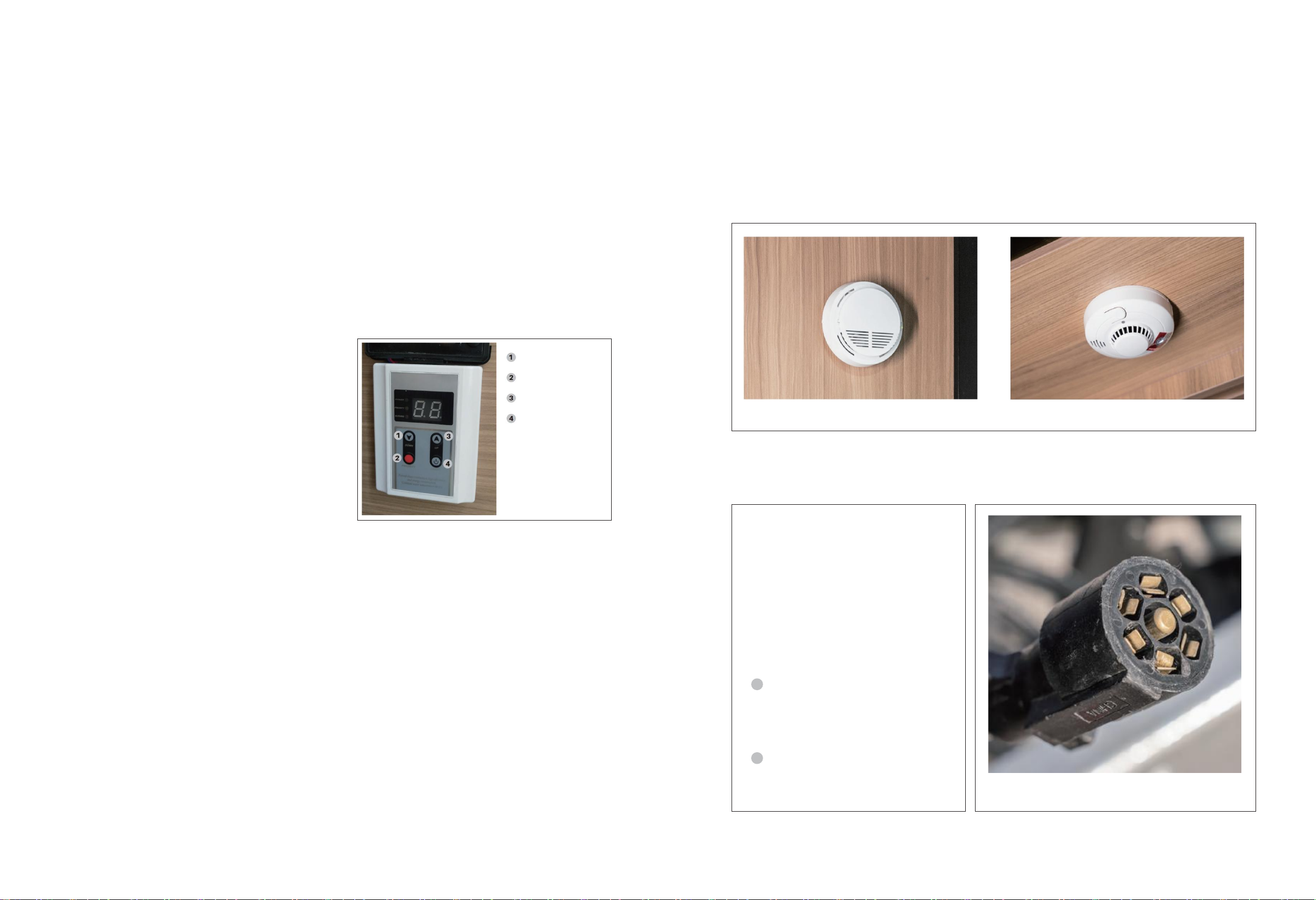
2.9 ALARMS
(1) Gas leak alarm
Gas leak alarm detects low-concentration combustible gas in the surrounding environment through the gas sensor. When
the concentration of combustible gas exceeds the set value of the alarm, the alarm will give alarm signals, prompting the
user to detect the gas leak and take timely measures to eliminate the danger.
Gas alarm value: LPG: 0.1%~0.5%.
(2) Smoke alarm
Smoke alarm is also an important device in the camper trailer. It is installed on the ceiling of trailer to prevent any fire in
the trailer caused by overloading of appliances or combustion of furniture. The device will immediately react to smoke and
the speaker beeps to alarm.
2.10 SIGNAL LIGHTS
The tractor is standard equipped with a 7-pin outlet and the camper trailer is standard equipped with a 7-pin plug. Insert
the 7-pin plug of the trailer into the 7-pin outlet of the tractor to synchronize the signal lights of the tractor and trailer.
2.7 INVERTER
Camper trailer is equipped with a 2,000W inverter or 3,000W inverter.
(1) Turn the main power switch in the battery compartment to “ON” position, and close the inverter fuse;
(2) When municipal power supply is accessible, switch on QF1, and the inverter is working in AC→DC mode and the battery is being
charged; as the inverter has the municipal power supply bypass function, the inverter will automatically transmit the municipal power
to the electrical devices on the branches when municipal power supply is accessed and QF1 and QF2 both are switched on. When the
municipal power supply is not accessible, close K1 and inverter is working in DC→AC mode; switch on QF2 at this moment and the
outlets on the corresponding branches are energized; turn off K1 and inverter stops working. See inverter instructions for specific
functions and operations.
2.8 HOOD
(1) Turn on the fan switch (on the bottom of hood);
(2) Turn on the light switch (on the bottom of hood).
See hood instructions for specific functions and operations.
Down
Confirm
Up
Power
Fig. 3-2
Fig. 3-4 Gas Leak Alarm Fig. 3-5 Smoke Alarm
Fig. 3-4 Gas Leak Alarm Figure: Picture of 7-Pin Plug
License plate light
From top to bottom:
Left steering light
Position light (stop light)
Side light
1
2

2.11 AIR CONDITIONER
(1) Insert the charging cable of municipal power supply to municipal power input outlet of trailer;
(2) Close the leakage protector switch QF1 in Fig. 3-1;
(3) Turn on and off the air conditioner using the remote control.
2.12 ELECTRIC STEP
Camper trailer is equipped with a retractable electric step for passengers to get in and get off from the vehicle. The step
is made of aluminum, lightweight, resistant to corrosion and has an anti-slip surface. The electric step is driven by a DC motor
and controlled via a dedicated switch.
CHAPTER III VEHICLE OPERATING INSTRUCTIONS
25 CHAPTER III VEHICLE OPERATING INSTRUCTIONS 26
3.3 SWITCHES OF EXTERIOR FRONT, REAR, LEFT AND RIGHT LIGHTS (FIG. 3-3)
(1) Exterior headlight switch control: Press the exterior headlight switch to turn on the headlights; press the exterior
headlight switch again to turn off the headlights.
(2) Exterior taillight switch control: Press the exterior taillight switch to turn on the taillights; press the exterior taillight
switch again to turn off the taillights.
(3) Exterior left light switch control: Press the exterior left light switch to turn on the exterior left light; press the exterior
left light switch again to turn off the exterior left light.
(4) Exterior right light switch control: Press the exterior right light switch to turn on the exterior right light; press the
exterior right light switch again to turn off the exterior right light.
(1) DC outlet circuit
When the main control switch
(left in Fig. 3-3) is turned on, all
DC outlets are energized to supply
power to DC loads.
(2) AC outlet circuit
3. SWITCHES OF INTERIOR LIGHTS AND STRIP LIGHTS AND SWITCHES OF EXTERIOR
FRONT, REAR, LEFT AND RIGHT LIGHTS
3.1 MAIN CONTROL SWITCH (FIG. 3-3)
The main control switch controls the DC relay, and the DC relay controls the DC load; except for the inverter and water
pumps, all DC loads are controlled by the main control switch. Press the main control switch, and the DC relay will be energized
and transmit power to the main control panel to control DC devices; press the main control switch again until the DC relay coil
is de-energized and no longer transmits DC12V main power to the main control panel, and all DC devices stop working.
3.2 SWITCHES OF INTERIOR LIGHTS AND STRIP LIGHTS (FIG. 3-3)
(1) Living room ceiling light control: Press the living
room ceiling light switch to turn on the ceiling light;
press the living room ceiling light switch again to
turn off the ceiling light.
(2) Living room strip light control: Press the living
room strip light switch to turn on the strip light; press
the living room strip light switch again to turn off the
strip light.
(3) Bedroom ceiling light control: Press the bedroom
ceiling light switch to turn on the ceiling light; press
the bedroom ceiling light switch again to turn off
the ceiling light. Fig. 3-3 Main Control Switch
4. DC AND AC OUTLET CIRCUITS
Fig. 3-7 Electric Step Fig. 3-8 Circuit of Electric Step
Figure: DC Outlet Circuit
Fig. 3-8 Circuit of Electric Step
(Control panel E) (Control panel J)
K (main control switch) Left branch Right branch
Electrical interface
Air conditioner,
shower, fridge,
water heater
Bar counter Microwave oven Bedroom
Control panel
Inverter Battery
Solar power
Controller
Living room TV
QF1: AC power supply
leakage protector
QF2: Inverter power supply
leakage protector

5. WATER LEVEL DISPLAY CIRCUIT
CHAPTER III VEHICLE OPERATING INSTRUCTIONS
27 CHAPTER III VEHICLE OPERATING INSTRUCTIONS 28
The chassis of camper trailer is equipped with 3 water tanks (drinking water tank, purified water tank and gray water tank), the
water gauges corresponding to the water tanks are drinking water gauge, purified water gauge and gray water gauge, the
water level indicators corresponding to the water gauges are drinking water level indicator, purified water indicator and
gray water level indicator. Three water gauges are installed on the control panels respectively (see Fig. 3-1). The principle
of water level display circuit is shown in Fig. 3-9.
6. ELECTROMAGNETIC BRAKE CIRCUIT
Camper trailer adopts electromagnetic brakes. Step on the brake pedal of tractor, and the brake controller outputs a brake
signal to the trailer’s brake disc through the 7-pin connector to synchronize the braking of tractor and camper trailer.
To prevent any accidents caused by separation of tractor and camper trailer in the travel, the camper trailer has a separate
emergency brake device to stop the trailer when the trailer is separated from the tractor.
7. ANDERSEN CHARGING CIRCUIT
Camper trailer is equipped with four 100Ah colloidal batteries. To ensure that the batteries are in good working condition, the
vehicle is designed with multiple charging modes, and different charging modes, including Andersen charging mode, can
coexist. The principle of Anderson charging circuit is shown in Fig. 3-11.
8. PV CHARGING CIRCUIT
Camper trailer is equipped with PV charging devices. PV panels with different powers are optional according to customer’s
requirements. PV charging
is efficient, energy-saving and eco-friendly, and is one of the important charging modes of camper trailers. The principle
of PV charging circuit is shown in Fig. 3-12.
Fig. 3-9 Water Level Display Circuit
Fig. 3-11 Andersen Charging Circuit
Fig. 3-12 PV Charging Circuit
PV panel
PV
controller
Trailer
batteries
Drinking water gauge Purified water gauge Gray water gauge
Water
level
indicator
Water
level
indicator
Water
level
indicator
Left RightBlue wire
White wire
7-pin plug
Fuse switch
Black (-)
Red (+) Black Blue White
White Red
From tractor
Stop light
6-way blade fuse box
Electric brake
fuse
Andersen plug
Fig. 3-10 Electromagnetic Brake Circuit
Silicon
rectifier
generator
Andersen
connector
Tractor
batteries
Trailer
batteries
Tractor part
Electronic voltage regulator

CHAPTER III VEHICLE OPERATING INSTRUCTIONS
29 CHAPTER III VEHICLE OPERATING INSTRUCTIONS 30
See Fig. 3-13 for mounting positions of water tanks.
II. OPERATING INSTRUCTIONS OF WATER SYSTEM
Water Tank Quantity of Each Model
DRINKING
WATER
TANK
PURIFIED
WATER
TANK
GRAY
WATER
TANK
BLACK
WATER
TANK
HQ21
45L
240L
100L
100L
HQ15
45L
240L
100L
100L
HQ19
45L
240L
100L
100L
HQ17
60L
190L
240L
-
HQ12
60L
240L
100L
100L
TH19
100L
200L
100L
100L
TH22 LJC
100L
200L
100L
100L
D1
0
200L
-
-
F3
0
100L
-
-
Water filling ports are arranged side by side. On the left is the water filling port of drinking water tank. On the right is the water filling
port of purified water tank. See Fig. 3-14.
1.1 WATER FILLING OF DRINKING WATER TANK
Remove the cap of water filling port of drinking water tank, add qualified
drinking water into the tank and observe percentage value on the drinking
water gauge at the same time, and stop adding until the tank is full (100%).
Caution: Disinfect and clean the drinking water tank before adding water.
1.2 WATER FILLING OF PURIFIED WATER TANK
The water filling steps of purified water tank are the same as 1.1.
1. WATER FILLING OF DRINKING WATER TANK AND PURIFIED WATER TANK
Camper trailer is equipped with a pull-out stainless steel outdoor
stove, easy to operate and space-saving. To use the stove, first unlock
it and then pull it out from the compartment; push it back into the
compartment after use and it will be locked automatically. When the
outdoor stove needs water supply (the water from the purified water
can be used only, without cold & hot water mixing), first connect the
stove to the “quick connector” of chassis water pipeline, then turn on
the purified water pump switch (“K5” in Fig. 3-1) on the control
panel, and finally turn on the purified water faucet in Fig. 3-16; push
it up to increase the water flow, and push it down to decrease the
water flow.
2. OPERATING INSTRUCTIONS OF OUTDOOR STOVE
1.3 INSTRUCTIONS FOR USE OF DRINKING WATER AND PURIFIED WATER
A. Instructions for use of drinking water
Camper trailer is equipped with 2 water pumps (drinking water pump
and purified water pump) on the vehicle. To use the water in the
drinkingwater tank, first turn on the drink water pump switch
(“K4” in Fig. 3-1) on the control panel, and then the drinking water
faucet in Fig. 3-15(turn the faucet clockwise to increase the water
flow, turn the faucet anti-clockwise to decrease the water flow); wait
for about 60s and then use water from the faucet (as the drinking
water pipeline has a purified water filtration system, water supply is
slightly delayed).
B. Instructions for use of purified water
To use the purified water, first turn on the purified water pump switch (“K5” in Fig. 3-1) on the control panel, and then the
purified water faucet (cold & hot water mixing faucet) in Fig. 3-15; push it up to increase the water flow and push it down to
decrease the water flow; purified water faucet mixes cold water and hot water; adjust the mixing ratio of cold water and hot
water by rotating the faucet up and down to obtain the expected water temperature.
Description: The hot water is available only when the water heater is working normally.
Shower devices are installed in the bathroom and outside the
camper trailer.
(1) To take a shower in the bathroom, first turn on the purified water
pump switch (“K5” in Fig. 3-1) on the control panel, and then take
off the shower head in Fig. 3-17. There are two switches on the back
of shower head for different spray modes; there is a cold & hot water
mixing faucet below the shower head to adjust the mixing ratio of cold
and hot water by pushing it to the left or right to obtain the expected
water temperature.
(2) The operating instructions for the outdoor shower are the same
as thosefor the indoor shower.
DESCRIPTION:
The hot water is available only when the water heater is working normally.
3. OPERATING INSTRUCTIONS FOR SHOWER DEVICES
Camper trailer is equipped with an electric toilet in the bathroom. To
use the toilet, first turn on the purified water pump switch (“K5” in
Fig. 3-18) on the control panel, and then press the solenoid valve
button on the toilet to open the solenoid valve and directly flush the
human waste from the drain pipe into the waste container.
4. OPERATING INSTRUCTIONS FOR ELECTRIC TOILET
Fig. 3-13 Mounting Positions of Water Tanks
Purified
water tank
Drinking
water tank Gray water tank
Fig. 3-14 Water Filling Ports of Drinking Water
Tank and Purified Water Tank
Purified water faucet
(cold & hot water mixing)
Basin
Drinking
water faucet
1
2
3
Fig. 3-15
Fig. 3-16
Fig. 3-17
Fig. 3-18 Electric Toilet
CHAPTER III VEHICLE OPERATING INSTRUCTIONS
31 CHAPTER III VEHICLE OPERATING INSTRUCTIONS 32
(1) OPERATING INSTRUCTIONS FOR DRINKING WATER TANK
Camper trailer has 1 drinking water tank, which is installed in the
middle of mounting area on the chassis and has a 60L volume. Clean
the drinking water tank of residues regularly to ensure the water
quality in the drinking water tank.
Cleaning method:
First add proper amount of neutral detergent from the filling port of
drinking water tank, and then add purified water until the tank is full;
Then open the outlet valve of the drinking water tank in Fig. 3-19, and
close the valve until the tank is empty.
Fill up the drinking water tank again with water and then drain the tank. Repeat the above steps several times until the
drinking water tank is completely clean.
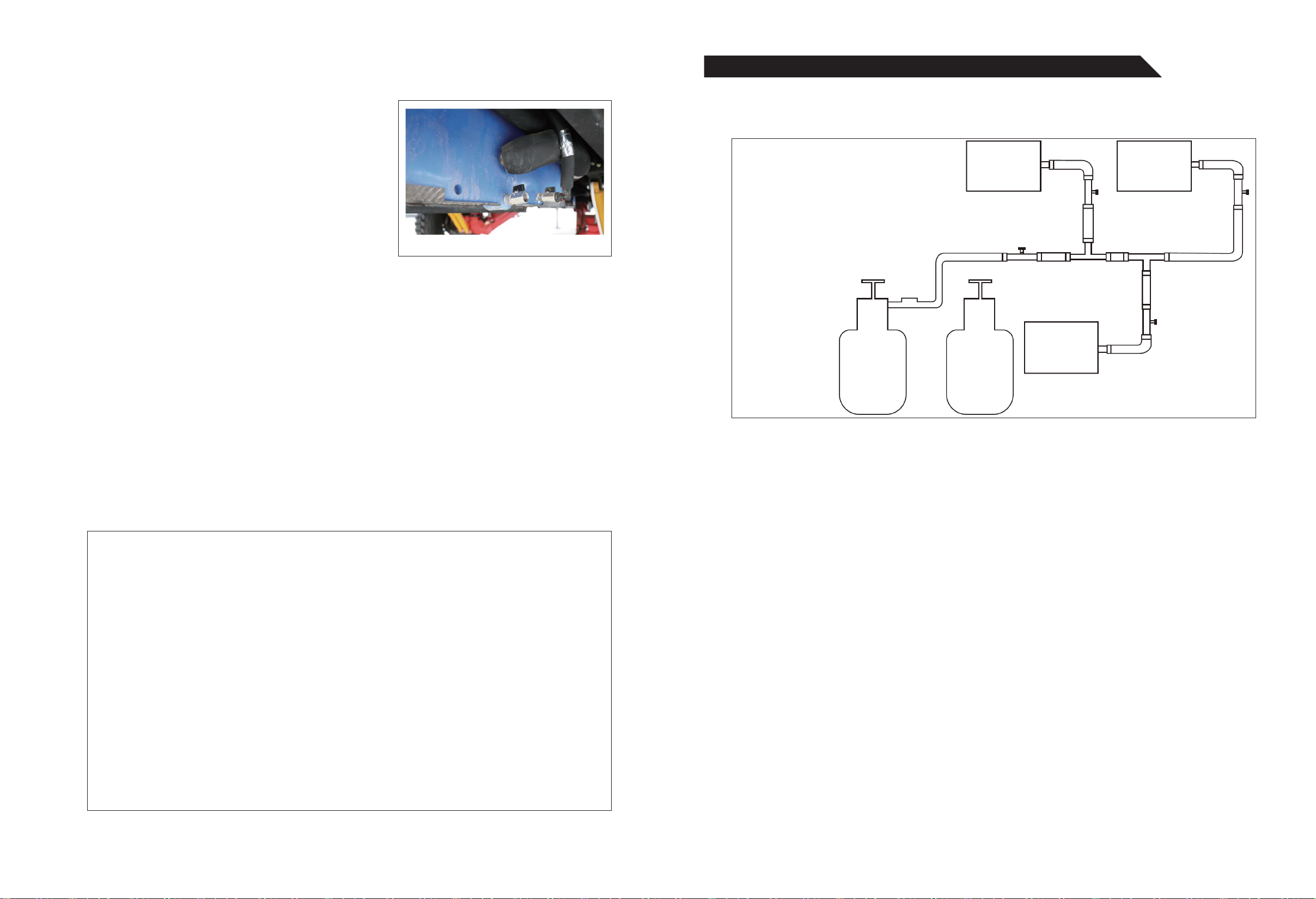
5. WATER TANKS III. OPERATING INSTRUCTIONS OF GAS SYSTEM
Gas system consists of the camper trailer consists of gas cylinders, pressure relief valve, main valve, branch valves, T-shaped
connectors, pipes, hoops and gas burning devices. Diagram of camper trailer’s gas system is shown in Fig. 3-22.
The gas cylinder compartment in front of the camper trailer can accommodate two gas cylinders, which should be purchased by the
user. The cylinder specification is 30kg and when filled up with LPG, it can support the user to live outdoors for one month.
LPG from the cylinder is high-pressure liquid and cannot be used directly. It should be de-pressurized before use. A main
valve is installed after the pressure relief valve to ensure safety and facilitate repair. Gas system has many branches. Copper
T-shaped connectors are installed at joints of branches. They are easy to install and have reliable performance. Gas system
uses high quality and safe LPG hoses that are resistant to oxidation and erosion. In order to improve the tightness at the hose
joints, the hose end is clamped onto the copper connector by a hoop using the hydraulic clamps.
(2) OPERATING INSTRUCTIONS FOR PURIFIED WATER TANK
Camper trailer has 1 purified water tank, which is installed on the rear end of mounting area on the chassis and has a
190L volume. Clean the purified water tank of residues regularly to ensure the water quality in the purified water tank. The
cleaning method is the same as that of drinking water tank.
(3) OPERATING INSTRUCTIONS FOR GRAY WATER TANK
Camper trailer has 1 gray water tank, which is installed on the front end of mounting area on the chassis and has a 240L
volume. The gray water tank is mainly used to collect water for washing face, brushing teeth, laundry and rinsing vegetables,
fruits and cleaning kitchenware.
Grey water tank stores domestic sewage, which contains chemical solutions such as detergent and must be discharged
at a place with discharge conditions or at an RV campground.
Before use of a gas burning device:
(1) Check whether all valves are closed;
(2) Open the gas cylinder valve;
(3) Open the main valve of gas system.
1. OPERATION OF GAS BURNING DEVICES
1.1 OPERATION OF INDOOR GAS STOVE
Open “main valve and branch valve 1” in Fig. 3-22, and then open “gas valve” of the gas stove successively; close the
“gas valve” of gas stove, “branch valve 1 and main valve” in turn after use.
1.2 OPERATION OF OUTDOOR GAS STOVE
Connect the pipeline of outdoor gas stove to the quick connector, then open “main valve and branch valve 2” in Fig. 3-22, and then
open “gas valve” of the gas stove successively; close the “gas valve” of gas stove, “branch valve 2 and main valve” in turn after use.
The correct method to connect the pipeline to quick connector is to align the “notch” on the quick connector to the “steel ball”.
OPERATING INSTRUCTIONS OF GAS SYSTEM
Fig. 3-19
Fig. 3-21
Outdoor
gas stove
Indoor
gas stove
Pressure
relief valve
Gas
cylinder 1
Gas
cylinder 2
(spare)
Water
heater
Branch valve 3Branch valve 2
Branch valve 1
Main valve
Fig. 3-22

CHAPTER III VEHICLE OPERATING INSTRUCTIONS
33 CHAPTER III VEHICLE OPERATING INSTRUCTIONS 34
IV. OPERATING INSTRUCTIONS OF FUEL SYSTEM
Camper trailer is fitted with an air parking heater, which uses diesel fuel as the combustion energy. The fuel system includes
fuel drum, filter, fuel pump, heater, air inlet line, exhaust gas discharge line, warm air output line and control panel.
A 5L fuel drum is installed in the fuel tank compartment in the right front of the camper trailer. Air parking heater can be
used in winter for people to stay warm. The fuel consumption varies according to the heater model and is generally about
0.3L/h. The filter screens out impurities in the fuel and ensures the air parking heater system work consistently. The fuel
pump is installed after the filter to ensure the fuel supply of heater. Heater is the core component of the entire system. It
burns the fuel supplied by the fuel pump to release heat. Air inlet line is to supply combustion air for the heater. The
hazardous gas produced in the fuel combustion will be discharged outdoors through the exhaust pipe. The heat produced from
the fuel combustion in the heater will be supplied to the carriage through warm air outlet line. Air parking heater is turned
on and off on the control panel.
The operating principle of fuel system is shown in Figure: Fuel System.
·The steel gas cylinders used for the trailer must comply with local regulatory requirements, and be regularly inspected
according to relevant provisions. The cylinders whose service life has expired should not be used.
·Cylinders should be installed vertically and secured firmly in the cylinder compartment in front of the camper trailer.
·Check the cylinder body, cylinder valve, pressure relief valve and connections for leaks before first use. Check leaks by
using suds (or gas leak detector). Open flame is forbidden.
·Ignition method: The correct ignition method is to first open the cylinder valve, main valve and branch valve of gas system, and
then open the electronic ignition switch of the gas stove; use a gas lighter to ignite the ordinary gas stove.
·Gas stove flame regulation: Regulate the gas stove flame according to different needs in use to satisfy cooking requirements.
·Do not leave the stove unattended to avoid spilling of soup or water, which will lead to gas leaks and thus result in poisoning
or fire accident.
·Complete combustion of LPG requires large amount of air, so keep kitchen and area around the gas stove well ventilated.
·Leaking LPG will be deposited in low-lying areas, not easily dissipate, and may be ignited when exposed to open flame or
sparks, resulting in fire or explosion and causing serious injury and property damage, even death. Therefore, once LPG leak
is noticed (LPG has a special smell, so leak is very perceptible), emergency measures should be taken immediately:
(1) Extinguish any open flame;
(2) Close cylinder valve, main valve and branch valve;
(3) Open door, windows and other vents;
(4) Do not touch any electronic switches;
(5) Leave this area and notify professional service personnel for timely maintenance.
·Make sure the leak of gas system has been eliminated before reuse.
·Once a fire occurs in use, immediately take effective measures to extinguish the fire. First, quickly close the cylinder valve
to cut off the gas source, and then cover the fire point with a wet towel or wet quilt to isolate it from the air and the flame
will be extinguished, and finally move the cylinder to a safe place, promptly ask the professional service personnel to check
the cause of the accident, and troubleshoot the hidden danger.
SAFETY PRECAUTIONS FOR GAS SYSTEM
OPERATING INSTRUCTIONS OF AIR PARKING HEATER:
(1) Fuel filling: Add diesel into the drum using a fueler until it’s full before using the heater. Select the fuel type according
to the region and season;
(2) Close the main control switch in Fig. 3-3 and then the air heater fuse (installed at the heater), and the air heater control
panel is illuminated;
(3) Press and hold the power button on the control panel of air parking heater until “on” is displayed on the panel, indicating
the air heating system starts working;
(4) Press and hold the power button on the control panel of air parking heater until “off” is displayed on the panel, indicating
the air heating system stops working.
The accompanying technical data includes one copy of operating instructions of air parking heater. See the instructions for
specific operations.
Since the pipeline of the system is long, it takes a while to exhaust gas and pump the fuel in first use of air heater. If the
first ignition fails, first turn off the power button on the control panel of air heater, disconnect the air heater fuse switch, and
then close the air heater fuse switch again, and turn on the power button on the control panel; under normal circumstances,
repeat these steps twice and the heater can be ignited.
Quick connector for gas pipeline
Quick connector for water pipeline
Main valve of gas cylinder
Pressure relief valve 1
Pressure relief valve 2
Main valve 2 (for water heater, fridge and oven)
Main valve 1 (for indoor and outdoor gas stoves)
1
2
1
23
4
5Fuel drum
Filter
Fuel pump
Air inle
Air parking heater
Control panel
Power
Indoor
Warm air
outlet
Exhaust outlet
Outdoor
Figure: Fuel Tank
Fuel drum
Filter
Figure: Fuel Tank Figure: Control Panel of Air

CHAPTER III VEHICLE OPERATING INSTRUCTIONS
35 CHAPTER III VEHICLE OPERATING INSTRUCTIONS 36
V. OPERATING INSTRUCTIONS OF AWNING
A manually operated awning is installed on the side of carriage of camper trailer. It can be unfolded in hot weather to block
the sun. To use the awning, first take out the handle crank, insert the hitch end into the rotating ring, grip the handle rod
with left hand, rotate the crank anti-clockwise with right hand and the awning is slowly unfolded. When the awning is fully
unfolded, place two poles upright at front of the awning, adjust the height and secure the poles.
First release the fastening bolts of poles, remove the poles, rotate the crank clockwise to fold the awning slowly. When the
awning is fully folded, take off the handle crank and put it into the storage compartment.
VII. OPERATING INSTRUCTIONS OF STABILIZER LEGS AND
GUIDE WHEELS
VI. OPERATING INSTRUCTIONS OF ELECTRIC STEP
Camper trailer is equipped with an electric step. Press down switch “II” in Figure: Step Switches to unfold the electric step. When
the electric step is in place, the limit switch will cut off the motor power automatically. Press up switch “I” in Figure: Step Switches
to retract the electric step. When the electric step is fully retracted, the limit switch will automatically cut off the motor power.
Camper trailer is equipped with 4 manually operated stabilizer legs with a height of 650mm, and the height can be adjusted
up to 880mm using the lifting bolt. Base of stabilizer leg can be turned within a certain angle to balance the vehicle; the
rotation locking device of stabilizer leg is used to lock the stabilizer leg firmly when it is extended or retracted.
Park the trailer on the level, solid and flat ground before using the stabilizer legs. Do not use stabilizer legs to support the trailer on
the slope or soft ground. When the vehicle is fully stopped, lay down the stabilizer legs in turn (pull the lever outward with force, place
upr ght and lock the stabilizer leg firmly), and then adjust the height of stabilizer legs in turn, so the loadis evenly distributed on 4 legs.
Retract the stabilizer legs in turn (pull the lever outward with force, place the stabilizer legs in the horizontal position and
lock them firmly) after the use.
1. OPERATING INSTRUCTIONS OF STABILIZER LEGS
2. OPERATION OF GUIDE WHEEL
Camper trailer is equipped with guide wheels. See Figure: Guide Wheel for specific operations.
OPERATING INSTRUCTIONS OF GUIDE WHEEL:
Step one (placing guide wheel in right position): pull the lever outward to place the guide wheel upright; step two
(fast lowering):rotate two bolts on the side clockwise using the crank to lower the guide wheel rapidly on the ground; step
three (locking): rotate two bolts on the side anti-clockwise using the crank to lock the guide wheel firmly (a little bit hard); step
four (tuning): rotate the top bolt using the crank to lift guide wheel to a suitable height.
PRECAUTIONS:
Lock the guide wheel firmly anti-clockwise, and press it down with proper force. Guide wheel should be vertical to the
ground, or it will be deformed or damaged. Handbrake of trailer must be secure when trailer is supported by guide wheels. Start
the vehicle after confirming the guide wheels are placed in horizontal position.
Park the trailer on the level, solid and flat ground before using the guide wheels. Do not use guide wheels to support the
trailer on the slope or soft ground. Retract the guide wheels (pull the lever outward with force, place guide wheels in the
horizontal position and lock them firmly) after use.
WARNING:
(1) Guide wheel should be vertical to the ground, or it will be deformed or damaged.
(2) Handbrake of trailer must be secure when trailer is supported by guide wheels.
(3) Start the vehicle after confirming the guide wheels are placed in the horizontal position.
WARNING:
(1) The stabilizer leg must be vertical
to the ground, or it will be deformed
or damaged.
(2) Balance the load evenly on 4 stabilizer
legs, or the trailer will be deformed.
(3) Start the vehicle after confirming
that all stabilizer legs are placed in
the horizontal position.
Figure: Manually Operated Awning Figure: Step Switches
Fixing plate of stabilizer leg
Extending & retracting device
Lever
Support rod
Guide wheel
Rotation locking device
of stabilizer leg
Lever
Lifting bolt
Stabilizer leg
Base of stabilizer leg
Figure: Stabilizer Leg
Figure: Guide Wheel

CHAPTER IV SAFE OPERATION OF VEHICLE, VEHICLE HAZARD MANAGEMENT, INSPECTION RULES FOR VEHICLE OPERATIONAL SAFETY 38
CHAPTER IV I. UNSUITABLE TRACTORS
The towing force required for the trailer should not exceed the maximum towing capacity of the tractor. If the towing capacity
of the tractor is not enough, a heavy trailer will become unstable and get out of control, resulting in injury, death or serious
safety accidents. In addition, the stresses attached to the tractor may cause serious damage to the engine and drive system.
&DANGER
A low-load tractor will make the trailer out of control, resulting in injury, death or serious safety accidents. Please make
sure a tractor that is suitable to your trailer is used.
II. SPEEDING
The recommended maximum speed to safely tow the trailer is 80km/h on the highway. If you drive too fast, the trailer is
likely to wobble, increasing the likelihood of losing control. Moreover, the tires will overheat, increasing the likelihood of a
blowout. When the tire bursts at high speed, it’s highly likely to lose the control of trailer.
&WARNING
Speeding can lead to loss of control of the trailer and injury, death or serious safety accidents. Precautions for towing the
trailer: When you’re towing a trailer, the turning radius is larger due to the longer braking distance. The trailer alters the
operating characteristics of the tractor, making it more sensitive to steering and more likely to be unstable in windy
conditions. Therefore, following requirements must be observed:
·Beware of slippery conditions. Driving a tractor towing the trailer is more prone to be affected by slippery conditions that
driving a tractor without towing a trailer.
·Foresee the “wobbling” of trailer. This is crucial. Harsh steering and wind gusts will make the trailer wobble. Pay full attention
to the reaction of the trailer to the pressure waves generated by passing trucks and buses.
·When the trailer is wobbling, take your foot off the accelerator pedal, steer as little as possible and drive in a straight
line. Steer the vehicle by “tuning”. Do not speed up to stop wobbling (you will escalate wobbling only). Do not use brake of
trailer to stop trailer from wobbling.
·Check the trailer and traffic frequently in the rear view mirror.
·Drive in a low gear on a steep slope or a long slope. Use the transmission as a brake. Do not apply the brakes because
they will overheat and fail.
·Pay attention to the height of your trailer, especially when approaching bridges and areas with roofs and near trees.
&WARNING
In order to ensure driving safety and avoid rollover caused by speeding and other violations, you must drive according to
the following speed requirements: The maximum speed of vehicle is 80km/h on paved and straight roads. Slow down in
advance according to traffic regulations to turn the corner.
Towing devices of the trailer include: 12,000lb towing device, retaining pin, pin circlip, two safety chains, U-shaped
buckle, 7-pin connector, Andersen plug, and emergency brake switch.
III. TOWING DEVICES OF TRAILER AND TRACTOR MUST
BE PROPERLY AND FIRMLY CONNECTED.
Figure: Retaining Pin and Circlip Figure: Safety Chain Figure: U-Shaped Buckle
SAFE OPERATION OF VEHICLE
VEHICLE HAZARD MANAGEMENT
INSPECTION RULES FOR VEHICLE
OPERATIONAL SAFETY
THE CONTENTS OF THIS CHAPTER ARE CRITICAL
TO SAFE DRIVING AND OPERATION OF TRAILER.
FOLLOWING THESE SAFETY RULES AND MAKING
THEM A HABIT IS THE ONLY EFFECTIVE WAY TO
AVOID SAFETY ACCIDENTS.
This manual suits for next models
9
Table of contents
Other Black Series Automobile Accessories manuals

Popular Automobile Accessories manuals by other brands


Havis-Shields
Havis-Shields 2004-2008 Ford Econoline Van C-VS-1800-ECO Install instructions

walser
walser Perma Protect User instructions

Metra Electronics
Metra Electronics 99-7337B installation instructions

TEINHOF
TEINHOF C-270 FITTING AND OPERATION MANUAL

Lectron
Lectron EVCharge14-50-32A user manual

TAUBENREUTHER
TAUBENREUTHER 16 - 6006 Installation instruction