202-A00 page 8/12
MAINTENANCE
VANE REPLACEMENT
NOTICE:
Maintenance shall be performed by qualified technicians
only, following the appropriate procedures and warnings
as presented in manual.
1. Remove the head assembly from the outboard (non-
driven) side of the pump according to steps 2 - 6 in the
"Pump Disassembly" section of this manual.
2. Turn the shaft by hand until a vane comes to the top (12
o'clock) position of the rotor. Remove the vane.
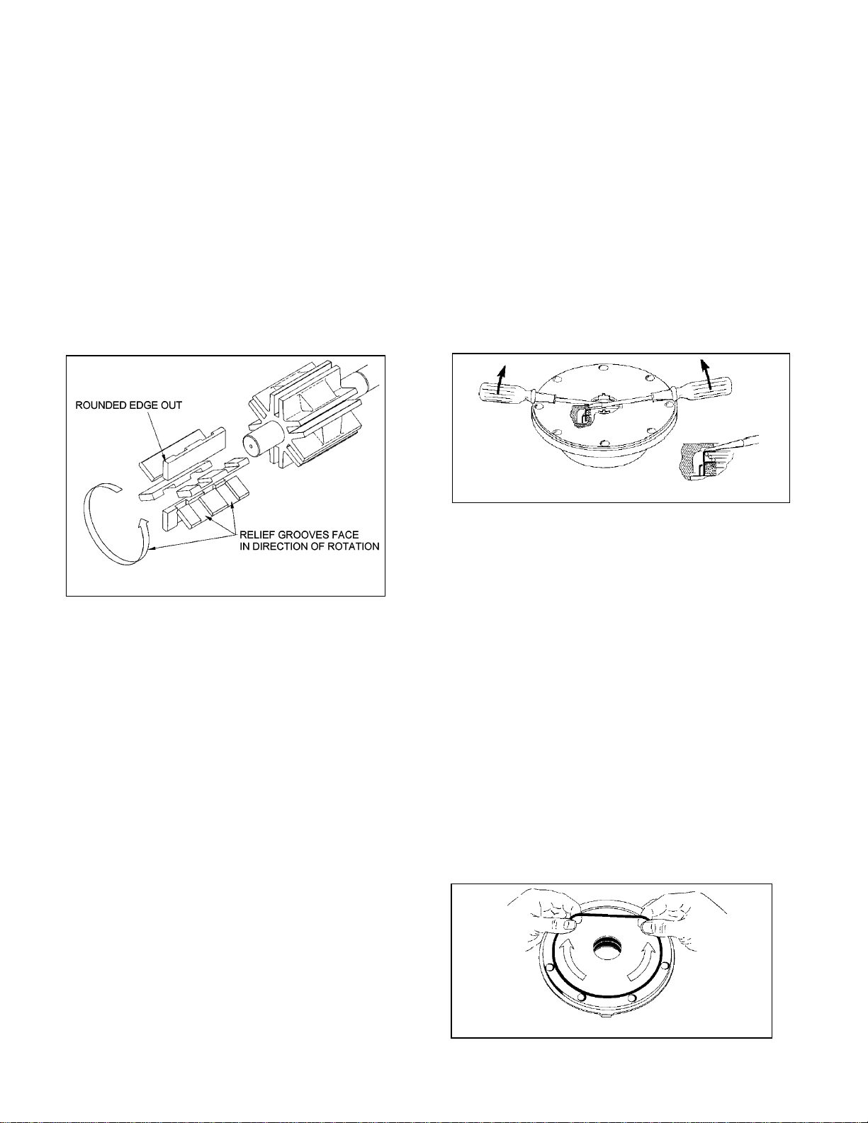
3. Install a new vane, ensuring that the rounded edge is UP,
and the relief grooves are facing towards the direction of
rotation. See Figure 4.
4. Repeat steps 2 and 3 until all vanes have been replaced.
5. Reassemble the pump according to steps 2 - 7 and 12 -
17 of the "Pump Assembly." section of this manual.
Figure 4
2-inch models have four (4) vanes.
PUMP DISASSEMBLY
NOTICE:
Follow all hazard warnings and instructions provided in
the “Maintenance” section of this manual.
1. Starting on the inboard (driven) end of the pump, clean
the pump shaft thoroughly, making sure the shaft is free of
nicks and burrs. This will prevent damage to the lip seal or
mechanical seal when the inboard head assembly is
removed.
2. Remove the inboard bearing cover capscrews (28) and
slide the inboard bearing cover (27A) and gasket (26) off
the shaft. Discard the bearing cover gasket. On 2 and 3-
inch models, the dirt shield (123A) will come off with the
bearing cover.
3. Remove the outboard bearing cover capscrews (28) and
slide the outboard bearing cover (27A) and gasket (26) off
the shaft. Discard the bearing cover gasket.
4. If equipped with locknuts and lockwashers (24A, 24B):
a. Bend up the engaged lockwasher tang and rotate the
locknut counterclockwise to remove it from the shaft.
b. Slide the lockwasher off the shaft. Inspect the
lockwasher for damage and replace as required.
c. Repeat steps a and b on the opposite shaft end.
5. Remove the head capscrews (21) and carefully pry the
head (20) away from the cylinder.
6. Slide the head off the shaft. The head O-ring (72), bearing
(24), and mechanical seal (153) or lip seal (152) will come
off with the head. Remove and discard the head O-ring.
a. Pull the bearing (24) from the housing in the head.
b. To remove the lip seal assembly (152), insert two
head capscrews (21) into the seal housing (152B) and
pull the lip seal assembly out. Use care not to damage
the lip seal. To remove the lip seal (152A), remove the
retaining ring (152D) from the housing, and gently pry
the lip seal from the housing. Remove and discard the
housing O-ring(s) (152C, 152E).
c. To remove the mechanical seal (153), use two screw
drivers to gently push the backside of the seal jacket
to push the seal from the head (see Figure 5). Use
care when placing the screwdrivers to prevent damage
to the seal faces. Remove and discard mechanical
seal O-rings.
Figure 5
7. Pull the rotor and shaft (13) from the cylinder (12). While
one hand is pulling the shaft, the other hand should be
cupped underneath the rotor to prevent the vanes (14)
and push rods (77) from falling out. Carefully set the
rotor and shaft, vanes and push rods aside for future vane
replacement and reassembly.
8. Remove the remaining components from the outboard
side of the pump, as instructed in steps 6 and 7 above.
PUMP ASSEMBLY
Before reassembling the pump, inspect all component
parts for wear or damage, and replace as required. Wash
out the bearing/seal recess of the head and remove any
burrs or nicks from the rotor and shaft.
1. Reassemble the OUTBOARD side of the pump first:
a. For a CLOCKWISE rotation pump, position the pump
cylinder with the INTAKE port to the left.
b. For a COUNTERCLOCKWISE rotation pump, position
the pump cylinder with the INTAKE port to the right.
2. Install a new head O-ring (72) in the groove in the head.
Lightly grease the outside circumference of the O-ring to
facilitate head installation. Start in on one side of the
groove, stretching ahead with the fingers, see Figure 6.
Figure 6