801-B00 Page 6/16
MOTOR DRIVEN PUMPS - INSTALLATION AND OPERATION
V-BELT DRIVE …. Continued
6. Adjust the motor base (183) and apply a specified force
(see Table 1) against the belt, at the center of the span,
so that the belt is deflected 1/64 inch (0.04 mm) for every
inch (25.4 mm) of span. For example, the deflection of a
20 inch (508 mm) span would be 20/64 or 5/16 inch (7.9
mm). The force required should be within the range given
in Table 1 for a properly tensioned drive. A new set of
belts should be initially tensioned to the upper limit.
BELT DEFLECTION FORCE
SMALL SHEAVE
OUTSIDE DIAMETER Minimum Maximum
2.5” to 4.5”
(63 mm to 114 mm) 3.0 lbs
(1.4 kgs) 4.75 lbs
(2.2 kgs)
4.75” to 7.0”
(121 mm to 178 mm) 4.0 lbs
(1.8 kgs) 6.0 lbs
(2.7 kgs)
Table 1 - Deflection Force Per Belt
7. Check again to ensure the sheaves (152 & 152D) are
parallel, then tighten the sheave capscrews (152C &
152G), the motor mounting nuts (183B) and the adjusting
screw locknut (183B).
8. Assemble the belt guard (182) and the belt guard brace
(182A) to the unit base (32).
Do not operate
without guard
in place
OPERATION WITHOUT GUARDS IN
PLACE CAN CAUSE SERIOUS
PERSONAL INJURY, MAJOR
PROPERTY DAMAGE, OR DEATH.
9. Check the belt tension after 24-48 hours of operating.
Recheck the tension periodically and tighten the belts as
required. DO NOT overtighten belts. Inspect belts
periodically for signs of excessive wear, and replace as
required.
V-BELT DISASSEMBLY
1. Remove the belt guard (182) and the guard base (182A).
Loosen the adjusting screw locknut (183B) on the motor
base (183) and the motor mounting nuts.
2. Ease the tension on the belts (181) by moving the motor
towards the pump to shorten the center distance of the
drive. Remove the belts by sliding them over the sheaves
(152 & 152D). DO NOT force the belts over the grooves.
3. To remove the sheave from the hub, first remove the
three sheave capscrews (152C or 152G). Then screw
two of the capscrews into the threaded holes in the
sheave hub (152A or E). If the cone grip is hard to break
loose, tap the end of the shaft or the QD hub with soft-
faced mallet while maintaining pressure on the screw.
4. The QD hub should slide smoothly off the shaft. If it is tight
on the shaft, gently pry it loose with a screwdriver or a small
wedge placed in the split part of the flange.
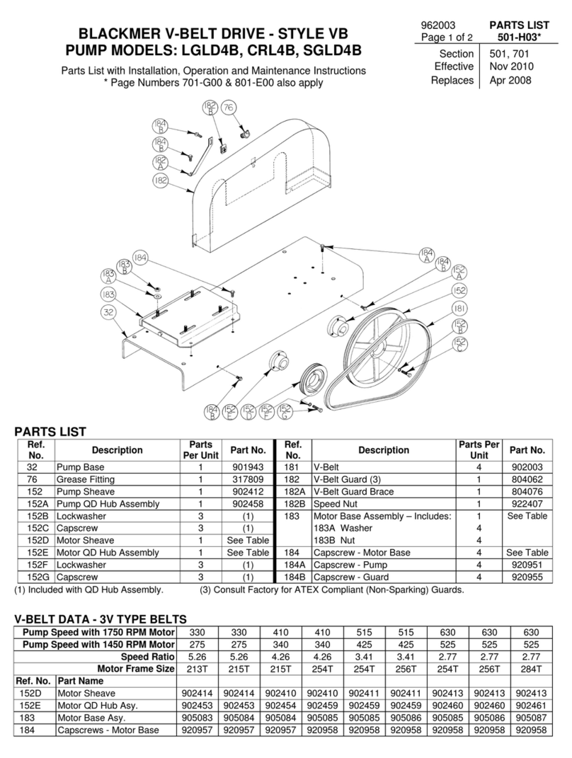
Refer to Blackmer V-Belt Parts List and Instructions for V-belt
drive and guard part numbers.
PRE-START UP CHECK LIST
1. Inspect complete piping system and supports to ensure
that no piping loads are being placed on the pump.
2. Install pressure gauges in the 1/4" NPT intake and
discharge ports located on the pump casing to check
pump performance after start-up.
3. Ensure all valves and fittings in piping system are in the
start-up or operating positions.
4. Jog the pump motor to verify proper pump rotation.
START UP PROCEDURES
NOTICE:
CONSULT THE "TROUBLESHOOTING" SECTIONS OF
THIS MANUAL IF DIFFICULTIES DURING START UP ARE
EXPERIENCED.
1. SLOWLY build pressure in the pump.
2. Start the motor.
3. Check pressure gauges to ensure the system is
operating within expected parameters. Record the gauge
readings in the "Initial Start Up Information" section of
this manual for future reference.
4. Inspect piping, fittings, and associated system equipment
for leaks, noise, vibration and overheating.
5. Check the flow rate to ensure the pump is operating
within the expected parameters. Record flow rate in the
“Initial Start Up” section of this manual.
6. Close the discharge valve and check the differential
pressure across the pump. Pressure must not exceed the
pressure setting of the external bypass valve.
7. With the discharge valve still closed, momentarily close
the manual shut-off valve in the bypass return line to
check the pump internal relief valve. The differential
pressure will be approximately 150 and 170 PSI (10.3
and 11.7 bar).
8. The external bypass valve must always be set at least 25
PSI (1.7 bar) lower than the internal pump relief valve.
NOTE: The normal operating pressure must be at least 5
- 15 PSI (0.3 -1.0 bar) less than the external bypass
valve setting. Pump speeds which result in higher
pressures (nearing the valve setting) forces the liquid to
recirculate, creating excessive wear on the pump and
equipment.
Hazardous pressure
can cause personal
injury or property
damage
PUMPS OPERATING AGAINST A
CLOSED VALVE CAN CAUSE SYSTEM
FAILURE, PERSONAL INJURY AND
PROPERTY DAMAGE

