205-A00 page 9/12
MAINTENANCE
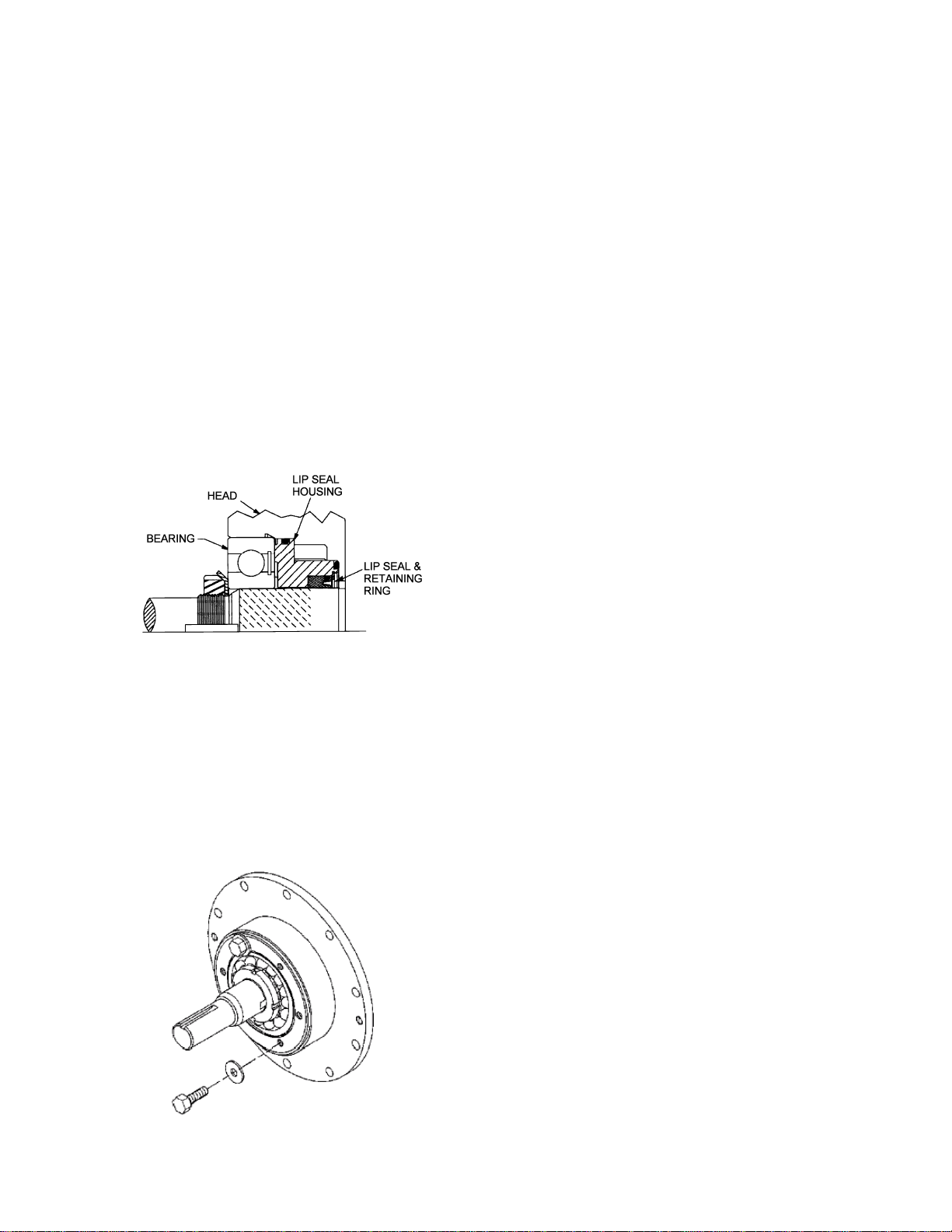
3. LIP SEAL ASSEMBLY (if equipped)
The lip seal assembly consists of a metal housing with
elastomer(s) around its outer diameter(s), and a PTFE lip
seal in its inner diameter. Refer to Figure 7.
a. Apply a small amount of light motor oil on the inner
diameter of the lip seal housing (152B) to facilitate
lip seal installation. Note: When installing the lip
seal, be careful not to damage the lip seal O-ring.
b. Push the lip seal (152A) squarely into the housing
(152B) with the pin in the lip seal aligned with the
hole in the back of the housing. The lip seal should
seat flush or slightly recessed in the housing, around
its entire diameter.
c. Insert the retaining ring (152D) into the groove in the
housing.
d. Install new housing O-ring(s) in the groove(s) of the
housing. Lightly grease the housing O-ring(s) and
push the lip seal and housing assembly into the
head recess with the lip seal inward. The lips of the
lip seal will face the rotor when the housing is
installed. Make sure the housing is bottomed out in
the back of the head.
Figure 7 – Lip Seal
4. MECHANICAL SEAL (If equipped)
Apply a small amount of motor oil in the head recess.
Push the mechanical seal assembly (153) into the recess
of the head with seal jacket drive tangs inward. The pin in
the stationary seat must be between the lugs in the back
of the head recess.
5. Hand pack the ball bearing (24) with grease. See the
‘Lubrication’ section.
6. Install the bearing into the head recess. The bearing balls
should face outward, with the grease shield inward.
Ensure that the bearing is fully and squarely seated
against the lip seal housing or mechanical seal.
Figure 8 Clamping the Bearing
a. On pumps equipped with a lip seal, install two 3/8"
(10 mm) washers and two bearing cover capscrews
(28) to clamp the bearing and compress the lip seal
housing inner O-ring for proper bearing locknut
adjustment (see Figure 8). The washers and
capscrews will be removed after the locknuts are
adjusted.
7. Turn the pump cylinder around and begin assembly on the
opposite, inboard end.
8. Remove the vanes (14) and push rods (77) from the rotor
and shaft assembly. Inspect for wear and damage, and
replace as follows:
a. Partially install the non-driven end of the rotor and
shaft (13) into the open side of the pump cylinder.
b. Leave part of the rotor outside of the cylinder so that
the bottom vanes can be installed and held in place
as the push rods are installed in the push rod holes
of the rotor. Insert the new vanes into the rotor slots
with the rounded edge outward, and the relief
grooves positioned as shown in Figure 3.
c. After the bottom vanes and push rods are installed,
insert the rotor and shaft fully into the cylinder.
d. Install the remaining vanes into the top positions of
the rotor. If equipped with a mechanical seal, rotate
the shaft by hand to engage the drive tangs of the
seal jacket in the rotor slots.
9. Install the inboard head, lip seal or mechanical seal, and
bearing as instructed in Steps 2 through 6. Apply a thin
coating of motor oil on the inboard shaft to aid installation.
10. Rotate the shaft by hand to engage the mechanical seal
drive tangs (if equipped), and to test for binding or tight
spots. If the rotor does not turn freely, lightly tap the rims
of the heads with a soft faced mallet until the correct
position is found. Install the remaining head capscrews for
each head, and uniformly torque to 25 Ibs ft (34 Nm).
11. LOCKNUT INSTALLATION
The bearing locknuts (24A) and lockwashers (24B) MUST
be installed and adjusted properly. Overtightening
locknuts can cause bearing failure or a broken lockwasher
tang. Loose locknuts will allow the rotor to shift against
the heads, causing wear. See Figure 9.
a. On both ends of the pump shaft, Install a lockwasher
(24B) with the tangs facing outward, followed by a
locknut (24A) with the tapered end inward. Ensure the
inner tang "A" of the lockwasher is located in the slot
in the shaft threads, bending it slightly, if necessary.
b. Tighten both locknuts to ensure that the bearings are
bottomed in the head recess. DO NOT overtighten
and bend or shear the lockwasher inner tang.
c. Loosen both locknuts one complete turn.
d. Tighten one locknut until a slight rotor drag is felt when
turning the shaft by hand.
e. Back off the nut the width of one lockwasher tang "B".
Secure the nut by bending the closest aligned
lockwasher tang into the slot in the locknut. The pump
should turn freely when rotated by hand.