Blackrock Microsystems NeuroPort User manual
Manufacturer
630 Komas Drive | Suite 200
Salt Lake City | UT 84108 | USA
P +1 (801) 582-5533 | F +1 (801) 582-1509
www.blackrockmicro.com
Revision 1.00 / LB-1070 – NeuroPort Biopotential Signal Processing System IFU – 05/2021
© 2021 Blackrock Microsystems, LLC
NeuroPort
Biopotential Signal
Processing System
Instructions for Use

Revision 1.00 / LB-1070 – NeuroPort Biopotential Signal Processing System IFU
© 2021 Blackrock Microsystems, LLC
2
Table of Contents
What This Manual Covers ............................................................. 6
Intended Use/Indications for Use .................................................. 6
Contraindications, Warnings, and Precautions ............................. 7
Contraindications .............................................................................. 7
Warnings .......................................................................................... 7
Precautions ...................................................................................... 7
Symbols ........................................................................................ 8
Specifications .............................................................................. 11
Neural Signal Processor ................................................................. 11
Front End Amplifier and Power Supply .......................................... 12
System Requirements ................................................................. 13
System Description ..................................................................... 13
NeuroPort System .......................................................................... 14
Hardware .................................................................................... 17
Neural Signal Processor (NSP) ...................................................... 17
Neural Signal Amplifier ................................................................... 20
Amplifier Power Supply (APS) ........................................................ 21
Cables ............................................................................................ 22
Accessories ................................................................................. 23
Headstages .................................................................................... 23
Digital Neural Signal Simulator (DNSS) ......................................... 23
Software ...................................................................................... 24
Central Main Window ..................................................................... 24
Menu Bar ........................................................................................ 26
File ............................................................................................... 26

Revision 1.00 / LB-1070 – NeuroPort Biopotential Signal Processing System IFU
© 2021 Blackrock Microsystems, LLC
3
Tools ............................................................................................ 26
Options ........................................................................................ 27
Windows ...................................................................................... 28
Hardware Configuration ................................................................. 29
Channel Sorting ........................................................................... 29
Configuring Channel Properties ................................................... 29
Front End Analog Inputs .............................................................. 30
Analog Output .............................................................................. 32
Analog Output: Continuous Monitor ............................................. 32
Analog Output: Spike Monitor ...................................................... 32
Analog Output: Sine Waveform ................................................... 33
Analog Output: Custom Waveform .............................................. 33
Analog Output: Triggering ............................................................ 34
Digital Input .................................................................................. 34
Digital Output ............................................................................... 35
Digital Output: Monitor Electrode ................................................. 35
Digital Output: Timed ................................................................... 36
Digital Output: Triggered .............................................................. 36
Serial I/O ...................................................................................... 36
Global Settings ............................................................................ 37
Filters ........................................................................................... 37
Auto Thresholding ........................................................................ 38
Spike Sorting ............................................................................... 38
Tools Menu .................................................................................. 40
Adaptive Filtering ......................................................................... 40
N-Trode Groups ........................................................................... 41
Spike Panel .................................................................................... 42
Spike Panel Settings .................................................................... 43

Revision 1.00 / LB-1070 – NeuroPort Biopotential Signal Processing System IFU
© 2021 Blackrock Microsystems, LLC
4
Raster Plot ...................................................................................... 43
Tool Bar ....................................................................................... 44
Single Neural Channel ................................................................... 45
Channel Configuration ................................................................. 45
Spike Display ............................................................................... 46
Manual Override Options ............................................................. 46
File Storage .................................................................................... 47
TOC Interface .............................................................................. 47
2.x Interface ................................................................................. 48
File Storage Options .................................................................... 48
Digital Oscilloscope ........................................................................ 49
Trigger Type ................................................................................ 50
Digital Filter Editor .......................................................................... 51
Activity Map .................................................................................... 52
Signal-to-Noise Ratio ..................................................................... 53
Neural Modulation .......................................................................... 54
Impedance Tester .......................................................................... 55
Crosstalk ........................................................................................ 56
N-Trode .......................................................................................... 57
Spike Display ............................................................................... 58
Add Comment ................................................................................ 58
nPlay Server ................................................................................... 58
Spike Sorting .................................................................................. 59
Histogram Peak Count (Automatic) ............................................. 59
Hoops (Manual) ........................................................................... 59
Manual PCA ................................................................................. 60
k-means PCA ............................................................................... 61
DBSCAN PCA ............................................................................. 62

Revision 1.00 / LB-1070 – NeuroPort Biopotential Signal Processing System IFU
© 2021 Blackrock Microsystems, LLC
5
How to Use Adaptive Filtering ........................................................ 62
Create Custom Filters .................................................................... 63
Renaming Multiple Channels ......................................................... 63
Remotely Control Data Recording .................................................. 64
Visualize an Input Channel on the Digital Oscilloscope ................. 64
Configure Raster Plot ..................................................................... 65
Change Electrode Map (Create a Map File) ................................... 66
Setup ........................................................................................... 68
Hardware Setup ............................................................................. 68
NeuroPort System ....................................................................... 68
Software Setup ............................................................................... 68
Installing Central Software Suite .................................................. 68
Setting up the Ethernet Connection ............................................. 68
Cleaning, Maintenance, and Disposal ........................................ 70
Cleaning ......................................................................................... 70
Maintenance ................................................................................... 70
Disposal .......................................................................................... 70
Magnetic Resonance .................................................................. 70
Troubleshooting .......................................................................... 71
Return Merchandise Authorization (RMA) .................................. 72
Warranty ..................................................................................... 73
Disposal ...................................................................................... 73
Support ....................................................................................... 74
Complaints ..................................................................................... 74

Revision 1.00 / LB-1070 – NeuroPort Biopotential Signal Processing System IFU
© 2021 Blackrock Microsystems, LLC
6
What This Manual Covers
The NeuroPort Biopotential Signal Processing System (NeuroPort System) is designed to
record and process neural signals from up to 256 surface or penetrating electrodes in addition
to auxiliary analog signals and digital experimental events. The system can acquire a variety of
biopotential signal types including electrocorticography, electroencephalography, and
electromyography. The system can perform real-time signal processing algorithms on neural
signals, including noise cancellation, digital filtering, simultaneous extraction of spike and field
potentials, and manual and automatic online spike sorting.
The NeuroPort Biopotential Signal Processing System is not a monitoring system. No
physiological alarms are provided. The acquisition and display of biopotential signals is for the
interpretation and use of the clinician.
Intended Use/Indications for Use
The Blackrock NeuroPort Biopotential Signal Processing System supports recording, processing
and displaying biopotential signals from various types of electrodes. Biopotential signals may
include Electrocorticography (ECoG), electroencephalography (EEG), electromyography (EMG),
electrocardiography (ECG), electrooculography (EOC) action potentials (AP), and evoked
potentials (EP).

Revision 1.00 / LB-1070 – NeuroPort Biopotential Signal Processing System IFU
© 2021 Blackrock Microsystems, LLC
7
Contraindications, Warnings, and
Precautions
Contraindications
• The NeuroPort System is a recording system and should not be used in
applications involving stimulation.
Warnings
• Read this entire manual prior to using the device.
• A thorough understanding of the technical principles and risks associated with
electrophysiological recording is necessary before using this product.
• Completion of the Blackrock Microsystems user training program is required prior
to the use of the NeuroPort System.
• Always operate the NeuroPort System in a clean environment.
• Only connect NeuroPort System components to properly tested, grounded and
dedicated AC outlets using only the Blackrock provided power cable to reduce
the risk of electrical shock or malfunction of product. Do not use an adapter for
ungrounded wall outlets.
• Do not connect the NeuroPort System to an outlet controlled by a wall switch,
multiple socket-outlet or extension cord to avoid fires or other electrical hazards.
• Do not use the NeuroPort System in the presence of flammable anesthetic
agents.
• Do not use the NeuroPort System for any use other than its listed intended use.
• Avoid strong static discharges from sources like televisions or computer monitors
because it can damage the electrical components of the system.
• Keep the NeuroPort System away from liquids. Contact with water, shower
spray, or wet surfaces can lead to the patient receiving an electrical shock.
• Connection of external instruments may compromise electrical safety compliance
with IEC 60601-1.
• The NeuroPort System should be disconnected from any electrodes during
cardiac defibrillation.
• The conductive parts of electrodes and their connectors, including neural
electrodes, should not contact other conductive parts including earth.
• Place the NeuroPort system in a secure location.
• Avoid tripping on cords connected to the NeuroPort system.
• Repair or maintenance is not allowed during equipment operation.
• Only plug in Blackrock approved equipment into the NeuroPort system.
• Do not connect the computer hosting the Central software to the internet.
Precautions
• Follow the restrictions of use for third party electrodes or arrays.
• Third party recording or control systems connecting to the NeuroPort System and
components must be electrically isolated for subject safety.

Revision 1.00 / LB-1070 – NeuroPort Biopotential Signal Processing System IFU
© 2021 Blackrock Microsystems, LLC
8
• Note that the fiber-optic cable is very delicate. Do not bend it (bend radius of 5.0
cm) or crush it.
Symbols
ISO 15223-1:2016 Medical Devices – Symbols to Be Used with Medical Device Labels,
Labeling, and Information to Be Supplied
Reference
Symbol
Title
Meaning
5.1.1
Manufacturer
Indicates the medical device
manufacturer.
5.1.2
EC Rep
Indicates the Authorized
representative in the European
Community.
5.1.3
Date of
Manufacture
Indicates date of manufacture and is
accompanied by a date.
5.1.4
Use-by Date
Indicates the date after which the
medical device is not to be used.
5.1.6
Catalog Number
Indicates the manufacturer’s catalog
number so that the device may be
identified. For Blackrock
Microsystems it is called the Part
Number (PN).
5.1.7
Serial Number
Indicates the manufacturer’s serial
number so that a specific medical
device can be identified.
5.2.3
Sterilized Using
Ethylene Oxide
Indicates that the device has been
sterilized using ethylene oxide.
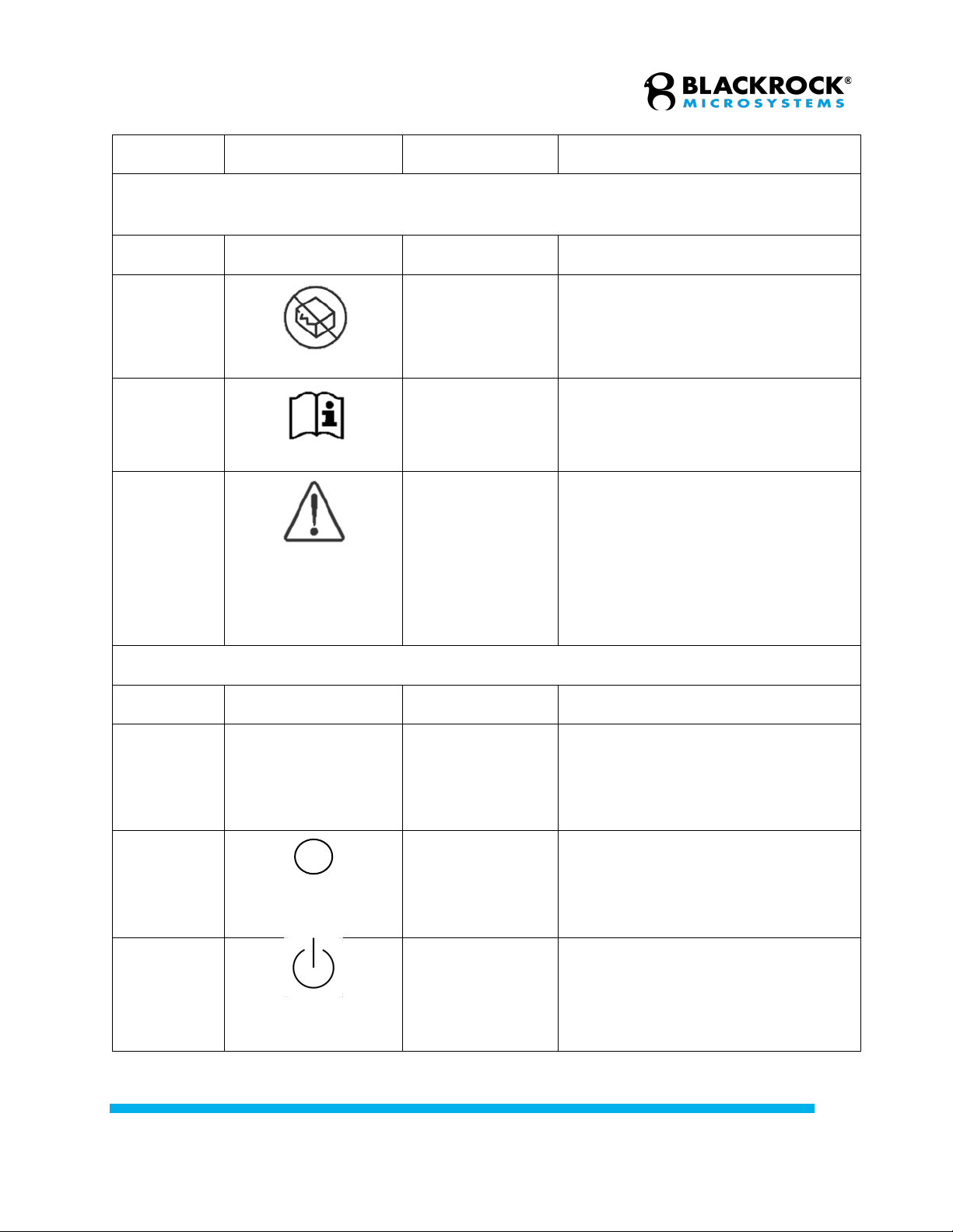
5.2.6
Do Not Reuse
Indicates a medical device that is
intended for one use, or for use on a
single patient during a single
procedure.
Revision 1.00 / LB-1070 – NeuroPort Biopotential Signal Processing System IFU
© 2021 Blackrock Microsystems, LLC
9
ISO 15223-1:2016 Medical Devices – Symbols to Be Used with Medical Device Labels,
Labeling, and Information to Be Supplied
Reference
Symbol
Title
Meaning
5.2.8
Do Not Use if
Package is
Damaged
Indicates that a medical device
should not be used if the package
has been damaged or opened.
5.4.3
Consult
Instructions for
Use
Indicates the need for the user to
consult the instructions for use, which
you are currently reading.
5.4.4
Caution
Indicates the need for the user to
consult the instructions for use for
important cautionary information such
as warning and precautions that
cannot, for a variety of reasons, be
presented on the medical device
itself.
IEC 60417:2002 DB Graphical Symbols for Use on Equipment
Reference
Symbol
Title
Meaning
5007
|
On (Power)
To indicate connection to the mains,
at least for mains switches or their
positions, and all those cases where
safety is involved.
5008
Off (Power)
To indicate disconnection from the
mains, at least for mains switches or
their positions, and all those cases
where safety is involved.
5009
Standby (Power)
To identify the switch or switch
position by means of which part of
the equipment is switched on in order
to bring it into the stand-by condition,
and to identify the control to shift to or
Revision 1.00 / LB-1070 – NeuroPort Biopotential Signal Processing System IFU
© 2021 Blackrock Microsystems, LLC
10
to indicate the state of low power
consumption.
IEC 60417:2002 DB Graphical Symbols for Use on Equipment
Reference
Symbol
Title
Meaning
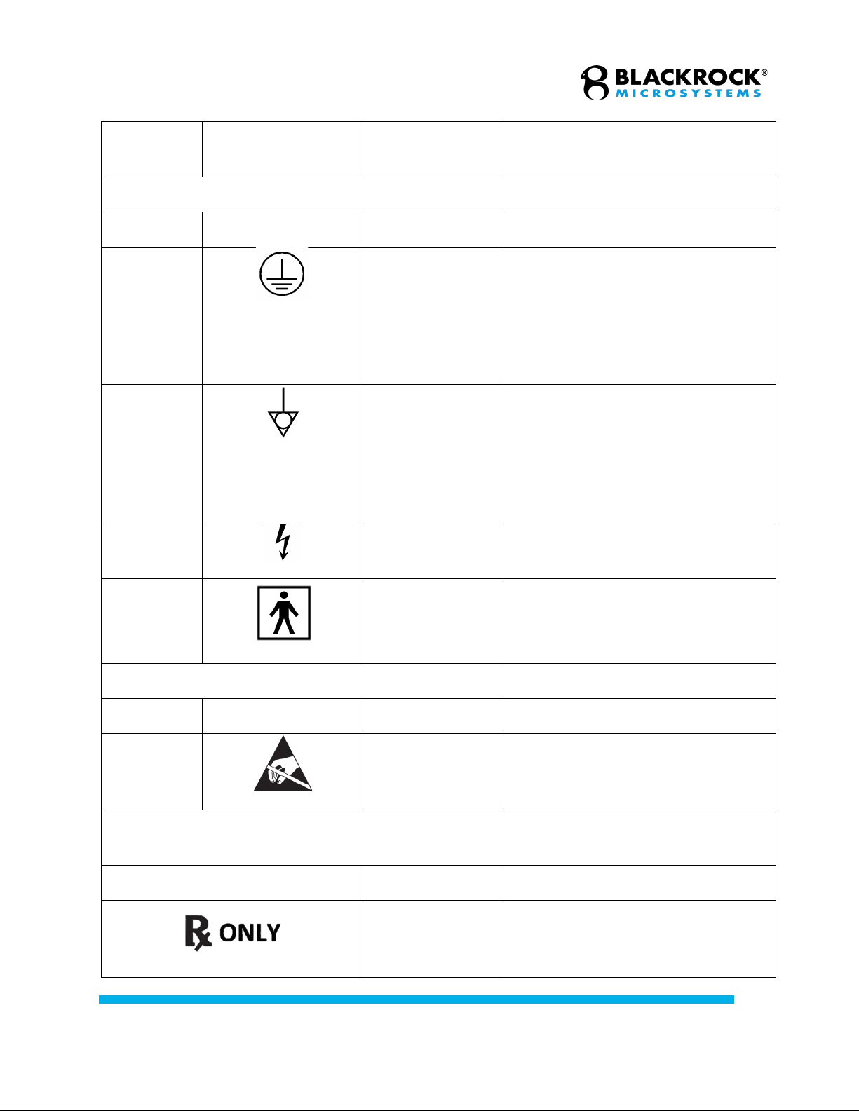
5019
Protective Earth
Ground
To identify any terminal which is
intended for connection to an
external conductor for protection
against electric shock in case of a
fault, or the terminal of a protective
earth (ground) electrode.
5021
Equipotentiality
Connector
To identify the terminals which, when
connected together, bring the various
parts of an equipment or of a system
to the same potential, not necessarily
being the earth (ground) potential,
e.g. for local bonding.
5036
Dangerous
Voltage
To indicate hazards arising from
dangerous voltages.
5333
Type BF Applied
Part
To identify a type BF applied part
complying with IEC 60601-1.
IEC 60101-1:2012 Medical Electrical Equipment: Basic Safety and Essential Performance
Reference
Symbol
Title
Meaning
0102
Danger of
Electrostatic
Discharge
Danger of electrostatic discharge
21 CFR 801. 109 (b) (1), 81 FR 38911 2016-09-13, U.S.A. FDA Guidance: Alternative to
Certain Prescription Device Labeling Requirements 2000-01-21
Symbol
Title
Meaning
Prescription
Only
Caution: Federal (U.S.A.) law
restricts this device to sale by or on
the order of a physician.

Revision 1.00 / LB-1070 – NeuroPort Biopotential Signal Processing System IFU
© 2021 Blackrock Microsystems, LLC
11
Specifications
Neural Signal Processor
Model Name
NeuroPort Neural Signal Processor
Neural Signal Inputs
Up to 256
Sampling Rate
30,000 Hz
Analog Inputs
Sixteen ±5 V, 16-bit inputs for experiment or neural signal processing
Digital IO
One 16-bit input port (DB-37) with Word and Packet Strobe control lines.
One RS232 I/O port (DB-9) with
115k baud input and output.
Four single-bit digital outputs (BNC) with programmable monitoring functions.
One TTL output (BNC) sampling synchronization output port.
Analog Outputs
Four ±5 V, 600 ohm, 16-bit outputs
Audio Outputs
Two ±1.5 V line-level outputs
PC Interface
1 Gbps Ethernet
Power Requirements
110 VAC 60 Hz 6.0 A / 240 VAC 50 Hz 3.0 A
Line Noise Serviceable
Fuses
5 x 20mm, 250V, 1.6A, Slow Blow
Compliance Standards
IEC 60601-1, IEC 60601-1-2, IEC 60601-2-26, CSA listed
Type of Protection
Against Electric Shock
Class I
Degree of Protection
Type BF Applied Part
Mode of Operation
Continuous
Water Ingress Protection
Ordinary Equipment, not fluid resistant, IPX0
Operating Environment
10˚C to 35˚C, 5 to 85% R.H. (non-condensing)
Revision 1.00 / LB-1070 – NeuroPort Biopotential Signal Processing System IFU
© 2021 Blackrock Microsystems, LLC
12
Storage Environment
-20˚C to 50˚C, 5 to 95% R.H. (non-condensing)
Front End Amplifier and Power Supply
Model Name
Front End Amplifier
Input Range
± 8.192 mV
Input Referred Noise
< 3.0µVrms (14µVp-p)
Input Impedance
> 1012 ohms || 3pF
Input Bias / Leakage
+5pA typical, ±20pA max
Analog to Digital
Conversion
16-bit digital output, with 0.25 µV per bit resolution
Common Mode Rejection
Ratio
> 90 dB at 50/60 Hz
Common Mode Input
Range
up to ±3.0 V between inputs and ground
Differential Input Range
up to ±3.0 V between electrode and reference inputs
Maximum Input Voltage
Range
up to ±5.0 V between any input and ground
Crosstalk
< 1 LSB for all configurations
Filter Characteristics
1st order Butterworth (high), 3rd order Butterworth (low)
0.30 Hz to 7.5 kHz
Power Supply to
Headstages
±5.0 V output, up to 150 mA for powering optional headstages

Revision 1.00 / LB-1070 – NeuroPort Biopotential Signal Processing System IFU
© 2021 Blackrock Microsystems, LLC
13
External Power Supply
Five channel with monitoring, sequencing, and emergency shutdown control
Input:
120 or 240 VAC, 50-60Hz
Outputs:
+5.0 V, 500 mA analog
–5.0 V, 500 mA analog
+3.3 V, 300 mA digital
+3.3 V, 500 mA digital
+5.0 V, 300 mA digital
System Requirements
The specifications listed below are the minimum required by the software to run. Blackrock
supplies an optional Host PC that is configured and tested by our engineers before it ships with
your NeuroPort system. Please contact [email protected] for more information.
• Microsoft Windows 7 (x64) or Windows 10 (x64)
• AMD or Intel 2.0 GHz Dual Core CPU
• 4 GB of RAM
• 1x Gbps Ethernet interface card
• 1 TB 3 Gbit/s SATA II HDD
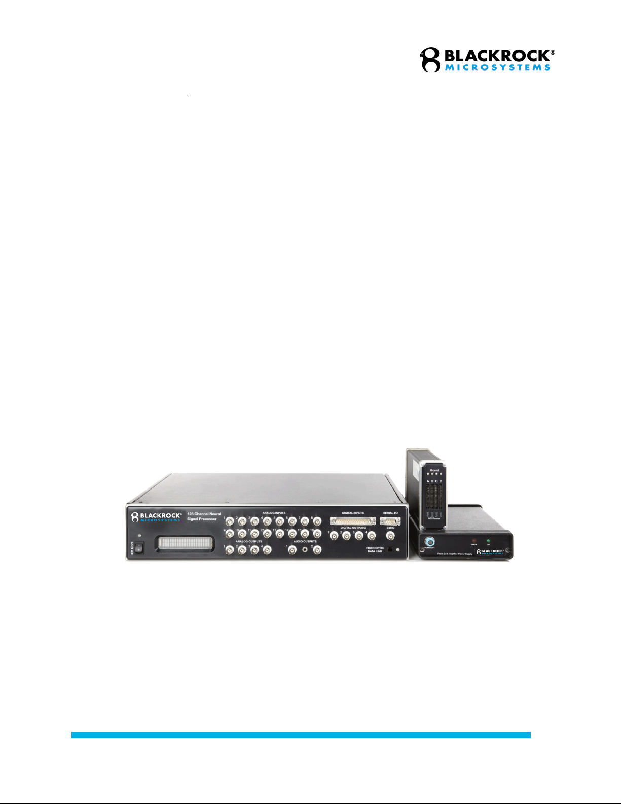
System Description
The diagrams below show an overview of the assembled system and subcomponents. Refer to
the sections below for more detailed information on each component.

Revision 1.00 / LB-1070 – NeuroPort Biopotential Signal Processing System IFU
© 2021 Blackrock Microsystems, LLC
14
NeuroPort System
Revision 1.00 / LB-1070 – NeuroPort Biopotential Signal Processing System IFU
© 2021 Blackrock Microsystems, LLC
15
Table 204–Guidance and manufacturer’s declaration – electromagnetic immunity – for all EQUIPMENT and
SYSTEMS that are not LIFE-SUPPORTING (refer to 60601-1-2).
Guidance and manufacturer’s declaration — electromagnetic immunity
The NeuroPort System is intended for use in the electromagnetic environment specified below. The customer or the user of the
NeuroPort system should assure that it is used in such an environment.
Immunity test
IEC 60601 test
level
Compliance
level
Electromagnetic environment — guidance
Portable and mobile RF communications equipment
should be used no closer to any part of the NeuroPort
system, including cables, than the recommended
separation distance calculated from the equation
applicable to the frequency of the transmitter.
Recommended separation distance
Conducted RF
IEC61000-4-6
3 Vrms
150 kHz to 80 MHz
3 Vrms
150 kHz to 80 MHz
80 MHz to 800 MHz
800 MHz to 2.5 GHz
Radiated RF
IEC 61000-4-3
3 V/m
80 MHz to 2.5 GHz
3 V/m
where P is the maximum output power rating of the
transmitter in watts (W) according to the transmitter
manufacturer and d is the recommended separation
distance in meters (m).
Field strengths from fixed RF transmitters, as deter-
mined by an electromagnetic site surveya should be
less than the compliance level in each frequency
rangeb.
Interference may occur in the vicinity of equipment
marked with the following symbol:
NOTE 1 At 80 MHz and 800 MHz, the higher frequency range applies.
NOTE 2 These guidelines may not apply in all situations. Electromagnetic propagation is affected by absorption and
reflection from structures, objects and people.
a Field strengths from fixed transmitters, such as base stations for radio (cellular/cordless) telephones and land
mobile radios, amateur radio, AM and FM radio broadcast and TV broadcast cannot be predicted theoretically with
accuracy. To assess the electromagnetic environment due to fixed RF transmitters, an electromagnetic site survey
should be considered. If the measured field strength in the location in which the NeuroPort system is used exceeds
the applicable RF compliance level above, the NeuroPort system should be observed to verify normal operation. If
abnormal performance is observed, additional measures may be necessary, such as reorienting or relocating the
NeuroPort system.
b Over the frequency range 150 kHz to 80 MHz, field strengths should be less than 3V/m.
Pd 2.1=
Pd 2.1=
Pd 3.2=

Revision 1.00 / LB-1070 – NeuroPort Biopotential Signal Processing System IFU
© 2021 Blackrock Microsystems, LLC
16
Table 206–Recommended separation distances between portable and mobile RF communications equipment
and the EQUIPMENT or SYSTEM - for EQUIPMENT or SYSTEMS that are not LIFE-SUPPORTING
(refer to 60601-1-2).
Recommended separation distances between portable and mobile RF communications equipment and
the NeuroPort system
The NeuroPort system is intended for use in an electromagnetic environment in which radiated RF disturbances
are controlled. The customer or the user of the NeuroPort system can help prevent electromagnetic interference
by maintaining a minimum distance between portable and mobile RF communications equipment (transmitters)
and the NeuroPort system as recommended below, according to the maximum output power of the
communications equipment.
Rated maximum
output power of
transmitter W
Separation distance according to frequency of transmitter m
150 kHz to 80 MHz
80 MHz to 800 MHz
800 MHz to 2.5 GHz
0,01
0.12
0.12
0.23
0,1
0.38
0.38
0.73
1
1.2
1.2
2.3
10
3.8
3.8
7.3
100
12
12
23
For transmitters rated at a maximum output power not listed above, the recommended separation distance d in
meters (m) can be estimated using the equation applicable to the frequency of the transmitter, where P is the
maximum output power rating of the transmitter in watts (W) according to the transmitter manufacturer.
NOTE 1 At 80 MHz and 800 MHz, the separation distance for the higher frequency range applies.
NOTE 2 These guidelines may not apply in all situations. Electromagnetic propagation is affected by absorption
and reflection from structures, objects and people.
P
V
d]
5.3
[
1
=
P
E
d]
5.3
[
1
=
P
E
d]
7
[
1
=

Revision 1.00 / LB-1070 – NeuroPort Biopotential Signal Processing System IFU
© 2021 Blackrock Microsystems, LLC
17
Hardware
Neural Signal Processor (NSP)
NSP showing the power switch (1), LCD display (2), analog inputs (3), digital inputs (4),
serial I/O (5), analog outputs (6), audio outputs (7), digital outputs (8), and sync port (9).
Note: The fiber optic link input connector has been relocated to the back panel in NSP
versions 1.75 and above. The location of this port was previously under the sync port on
the front panel
The NSP is the real-time processor of the system. It performs all the digital processing of
the signals, such as digital filtering, spike extraction, spike sorting. It also processes the
data and transmits it to the Host PC through Ethernet UDP protocol. The NSP has
multiple analog and digital input and outputs that can be programmed through the
software or one of the supplied Software Development Kits (SDKs). Multiple NSPs may
be synchronized for recording signals from a very large quantity of electrodes.
Power switch:
It is used to turn the NSP ON and OFF. The LED above the switch will illuminate blue
when the unit is on.
Note: On NSP PN-7530, PN-9650, and PN-10411 this switch is a momentary switch to
power down the NSP and does not turn main power to the device ON/OFF. See rear
panel for mains switch for mentioned part numbers.
LCD Display:
It displays the current operating status of the unit. The statuses include, “Initializing”,
“NSP Startup”, “NSP Running”, “NSP Standby”, and “Synchronized”.
Analog Inputs:
Auxiliary analog signals can be recorded through 16 analog input BNC ports. The analog
source may range ±5.0 V and should come from a source impedance of less than 100
Ω. The coupling of each input channel can be manually selected in the software. By
default, channels 1-8 are AC-coupled and channels 9-16 are DC-coupled.
Figure 1–NSP Front

Revision 1.00 / LB-1070 – NeuroPort Biopotential Signal Processing System IFU
© 2021 Blackrock Microsystems, LLC
18
Digital Input:
Digital events can be recorded through the 16-bit DB37 input port. The pin diagram is
shown below. DS is the digital strobe pin. D0-15 are data pins. EOP is reserved. SYNC
is an output pin and can be used with external equipment to indicate when the port is
scanned. Input range is 0V-5V TTL levels. The port is polled every 1/30000 of a
second. Strobed data is buffered up to 10 strobes per 1/30000 of a second and is
latched on the rising edge of the DS pin.
Serial I/O:
The port is an RS232 DB9 digital input/output port. The pin diagram is shown below.
Currently, the software only supports this port as an input. Pin 2 is “Receive Data”, pin 3
is “Transmit Data”, and pin 5 is “Ground”. The configuration of the port is: Baud rate:
115200, Data bits: 8, Parity: none, Stop bits: 1, Flow control: disabled.
Analog Outputs:
Four ±5.0 V analog output BNC connectors can be used to send monitoring signals or
stimulus waveforms to other connectors.
Audio Output:
The system sends a ±1 V line-level audio signal of the selected data channel to two BNC
ports (Left and Right channeled respectively) and one 3.5mm female stereo audio
connector simultaneously.
Digital Outputs:
Four single-bit digital BNC outputs can be programmed for monitoring or timing
functions. These ports can be setup to send a TTL signal if spike activity is detected on
any particular neural channel. They can also be configured to output a digital pulse train
at a user-defined frequency and duty cycle. Digital Output 1 can also be used for syncing
external equipment by sending a unique pulse every 14 seconds. The entire sync
pattern will repeat every hour. See the Central Software Suite User Manual for more
details.
Sync Port:
A synchronization pulse can be set as an optional line to inform external equipment
when the NSP neural signal inputs and front panel ports are scanned. It is active on the
rising edge of the signal.
Figure 2–Digital In Pin Diagram
Figure 3–Serial I/O Pin Diagram

Revision 1.00 / LB-1070 – NeuroPort Biopotential Signal Processing System IFU
© 2021 Blackrock Microsystems, LLC
19
NSP PN-4176
NSP PN-7530
NSP PN-9650
NSP PN-10411
Figure 4–NSP Back
Revision 1.00 / LB-1070 – NeuroPort Biopotential Signal Processing System IFU
© 2021 Blackrock Microsystems, LLC
20
Line Noise Cancellation Port:
On PN-4176 hardware Line Noise Cancellation receptacle is combined with the main
power receptacle. On PN-7530, PN-9650 and PN-10411 a separate power receptacle is
used for hardware line noise cancellation. To use this feature, plug a standard power
cable into this port and enable the feature in software as described in the Central
Software Suite User Manual.
Note: This receptacle is optional and is not required to power and operate the NSP
under normal conditions.
Synchronization Port:
This DB9 port is located on the back of the NSP and it is used to synchronize two NSPs.
The synchronization occurs automatically as Central runs on both computers if the sync
cable (Blackrock Part# 5584) is properly connected between two NSPs. Some models
may not have this port. To add synchronization capability to your NSP, please contact
Blackrock Microsystems support at [email protected]
Fiber-optic Link:
This port connects to the Amplifier using a fiber-optic cable. An LED to the right of the
connector turns green when a link is established and turns yellow when the link is
broken.
Mains Power Entry:
This supplies main power to the NSP and is required to power and operate the NSP.
Mains Power Switch:
Power switch used to turn main power ON/OFF to the NSP. Ensure this switch is in the
ON position marked by the “I” on the switch.
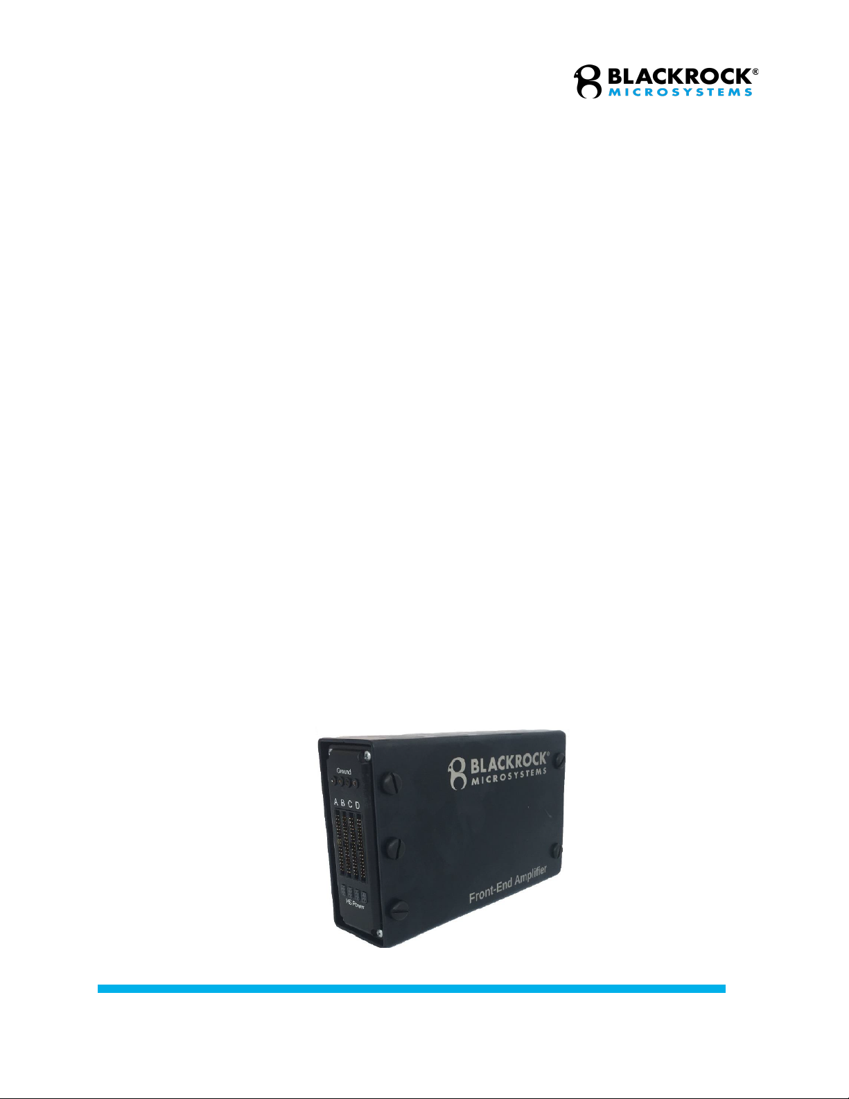
Neural Signal Amplifier
The Amplifier receives analog signals directly from the electrodes or via headstages
(e.g. unity-gain voltage followers) depending on the impedance of the electrodes. The
analog signals are amplified, filtered (1st-order high-pass at 0.3 Hz and 3rd-order low-
pass at 7,500 Hz), and digitized (30 kHz, 16-bits at 250 nV resolution), converted into
the optical domain and then transmitted to the NSP via a fiber-optic link, which is
immune to electromagnetic field interference. At a later stage, digital filtering will allow
these two signals to be separated and recorded in different data files.
Figure 5–Neural Signal Amplifier
Other manuals for NeuroPort
2
Table of contents
Other Blackrock Microsystems Recording Equipment manuals


