Blade ALPHA Pro-Tec PLUS 50 Supplement
INSTALLATION & SERVICE MANUAL
FOR
BLADE WATER HEATER
Models WH050, WH070, WH090 & WH115
With 200 or 300 litre storage cylinders
INCLUDES ALPHA
Pro-Tec PLUS 50,70,90 & 115 Boiler manual
BLADES LOW CARBON SYSTEMS Ltd
4 Valhalla Industrial Estate, Holsworthy, Devon EX22 6HN
For Technical help or Service call...01566 770799
For use with Natural Gas or Propane Gas (LPG)
Leave these instructions with the User


Blade 50,70,90,115 Water Heater Manual April 2020
1
Contents Page
1.0 INTRODUCTION 2
2.0 WATER HEATER TECHNICAL DATA 3
3.0 WATER HEATER SCHEMATIC LAYOUT 4-5
4.0 INSTALLATION REQUIREMENTS 6
5.0 EQUIPMENT DETAILS 7-11
6.0 FIXING DETAILS 12
7.0 GENERAL SERVICES REQUIREMENTS 13
8.0 MAINTENANCE & SERVICING CLEANCES 14-15
9.0 FRAME DETAILS 16
10.0 INSTALLATION SCHEMATIC 17
11.0 CONVERSION TO SPACE HEATING DETAILS 18
12.0 ROUTINE SERVICING 19
13.0 WIRING DIAGRAM 20
14.0 SHORT PARTS LIST 21
15.0 COMMISSIONING DETAILS 22-23
SERVICE RECORDS 24-27
NOTES 28
APPENDIX “A” ALPHA BOILER MANUAL 29
APPENDIX “B” DAB PUMP MANUAL

2
Blade 50,70,90,115 Water Heater Manual April 2020
1.0 INTRODUCTION
THIS MANUAL SHOULD BE READ IN CONJUNCTION WITH THE ALPHA INSTALLATION AND SERVICING
MANUAL FOR THE Pro-Tec Plus 50, 70, 90,& 115 BOILERS WHICH IS APPENDED TO THIS MANUAL IN
APPENDIX “A” AND SHOULD BE ADHERED TO IN ALL RESPECTS WHERE APPLICABLE
The boiler must only be used in conjunction with flue components supplied by ALPHA unless written
consent to use an alternative is obtained prior to installation from Blades LCS
The boiler and cylinder must be checked and serviced annually in accordance with section 6.0
in the Alpha Boiler Manual and section 7.0 and relevant items shown in the commissioning and
service check list on pages 22-23 of this manual. Failure to comply with this note may invalidate
the warranty. A service record logbook must be kept on site at all times detailing date of service,
any action undertaken.
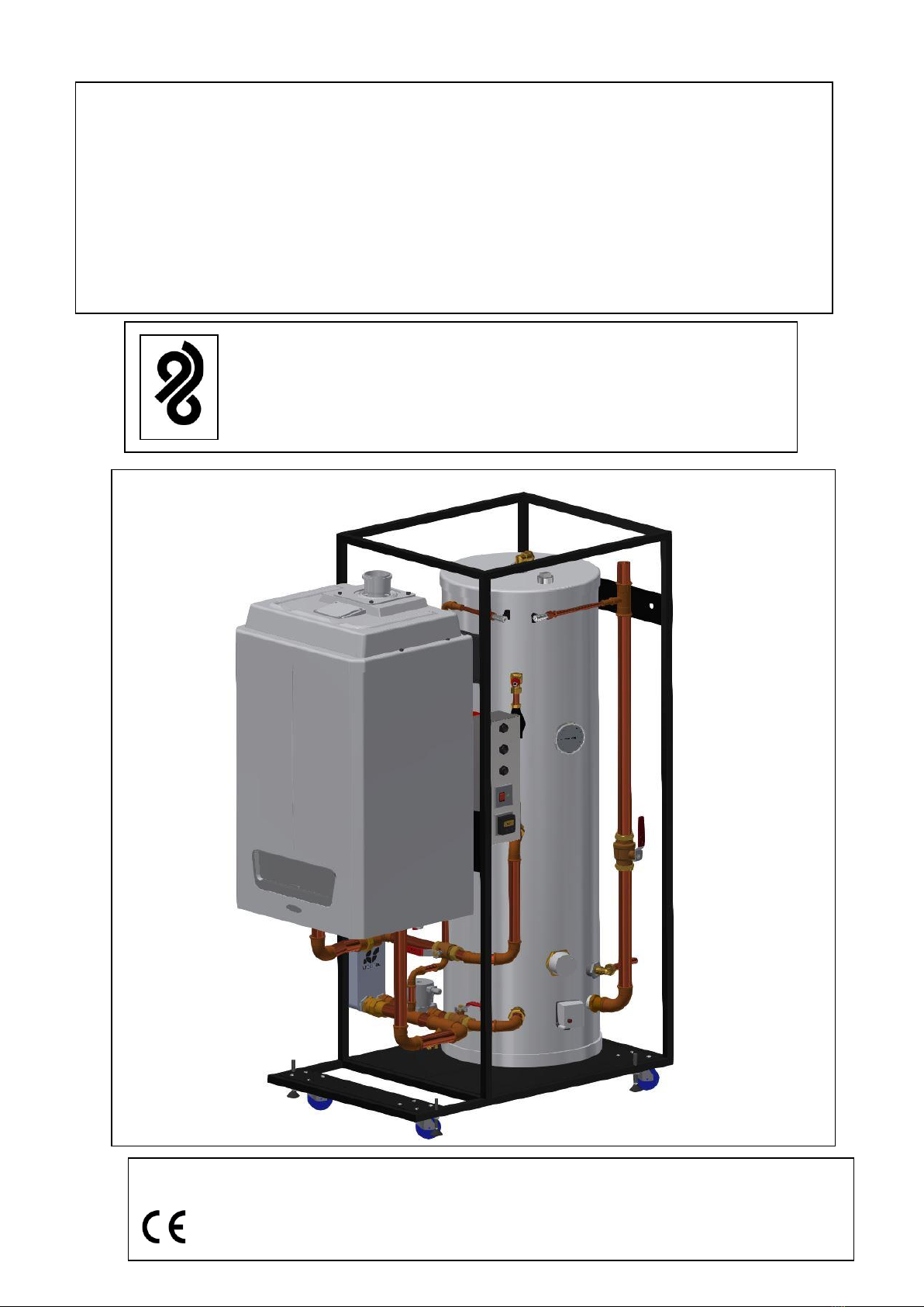
The Blade Water Heater has been specifically developed as a compact energy efficient boiler cylinder
module for use where high domestic hot water volumes are required.
The Water Heater can also be configured to supply space heating if required
Each Water Heater incorporates a high efficiency condensing fan assisted system boiler. See ALPHA
manual Appendix A for boiler performance data.
The burner is ignited electronically and the heat output is controlled by a modulating fan and gas valve.
Together with a 200 or 300 litre stainless steel domestic hot water storage vessel with all necessary
inter- connecting pipework, hot water circulating pump, plate heat exchanger, internal controls and
wiring terminating at convenient interface points for extension into the building services.
Theequipment is mounted within a rigid powder coated mild steelmobile frame suitable for free-standing
within the plant room.
Each boiler has a built-in controls system allowing boilers to operate as part of a modular system or
individually dependent on application.
The boiler is fitted complete with a DHW time control, switch live for external CH control and a remote boiler
fault indication signal connection.
The units are factory tested prior to dispatch, allowing ease of installation with reduced on-site works
requirement.
The benefit of the Water Heater is that by the incorporation of a high recovery plate heat exchanger with
acylinderdestratification pumptherecoverytimecanbedramatically reduced . This allows high volumes
of DHW to be delivered from a compact 200 or 300 litre storage cylinders, reducing cylinder heat losses
and increasing the overall energy efficiency of the system.
To increase fault tolerance the cylinder is fitted with a manually operated 3kW immersion heater.
.
Blade 50,70,90,115 Water Heater Manual April 2020
3
2.0 WATER HEATER TECHNICAL DATA
WH050
WH070
WH090
WH115
Overall Footprint (mm)
700W x 1253L
700W x 1297L
700W x 1427L
700W x 1427L
Height (mm)
1910
1910
1910
1910
Shipping Weight 300litre
210kg
240kg
260kg
267kg
Shipping Weight 200litre
200kg
229kg
249kg
256kg
Weight full 300litre
556kg
586kg
613kg
622kg
Weight full 200 litre
435kg
465kg
492kg
501kg
OVERALL PERFORMANCE DATA
All Models
DOMESTIC HOT WATER SYSTEM
200 & 300 litre
200 & 300 litre
Boiler Size
50 & 70kW Models
90 & 115kW Models
Max. Working System Pressure
3 bar
3 bar
Min. System Pressure
0.5 bar
0.5 bar
Pre-set Cylinder Temperature
60°C
60°C
Pressure and Temperature Relief Valve
Setting
7 bar
7 bar
DHW Flow Connection
35mm
42mm
DHW Return Connection
28mm
28mm
Gravity or Mains Cold Feed
35mm
42mm
Immersion Heater Rating
3 kW
3 kW
System Resistance
less than 0.5 bar
Less than 0.5 bar
WH050
WH070
WH090
WH115
DOMESTIC HOT WATER PERFORMANCE
VALUES
Heat up from cold 10°C 200 litre
14 min
10min
8min
6min
Heat up from cold 10°C 300 litre
21min
15min
12min
9.5min
ELECTRICAL
WH050
WH070
WH090
WH115
Supply Main Water Heater
V-50Hz
230/240V
230/240V
230/240V
230/240V
Supply Main Immersion heater
V-50Hz
230/240V
230/240V
230/240V
230/240V
External Fuse Water Heater
3 A
3 A
3 A
3 A
External fuse Immersion heater
13A
13A
13A
13A
Power Consumption DHW pump
75 W
75 W
75 W
75 W
Power Consumption Pressurisation unit *
50W
50W
50W
50W
•DENOTES Pressurisation unit is an Optional extra and not fitted as standard
4
Blade 50,70,90,115 Water Heater Manual April 2020
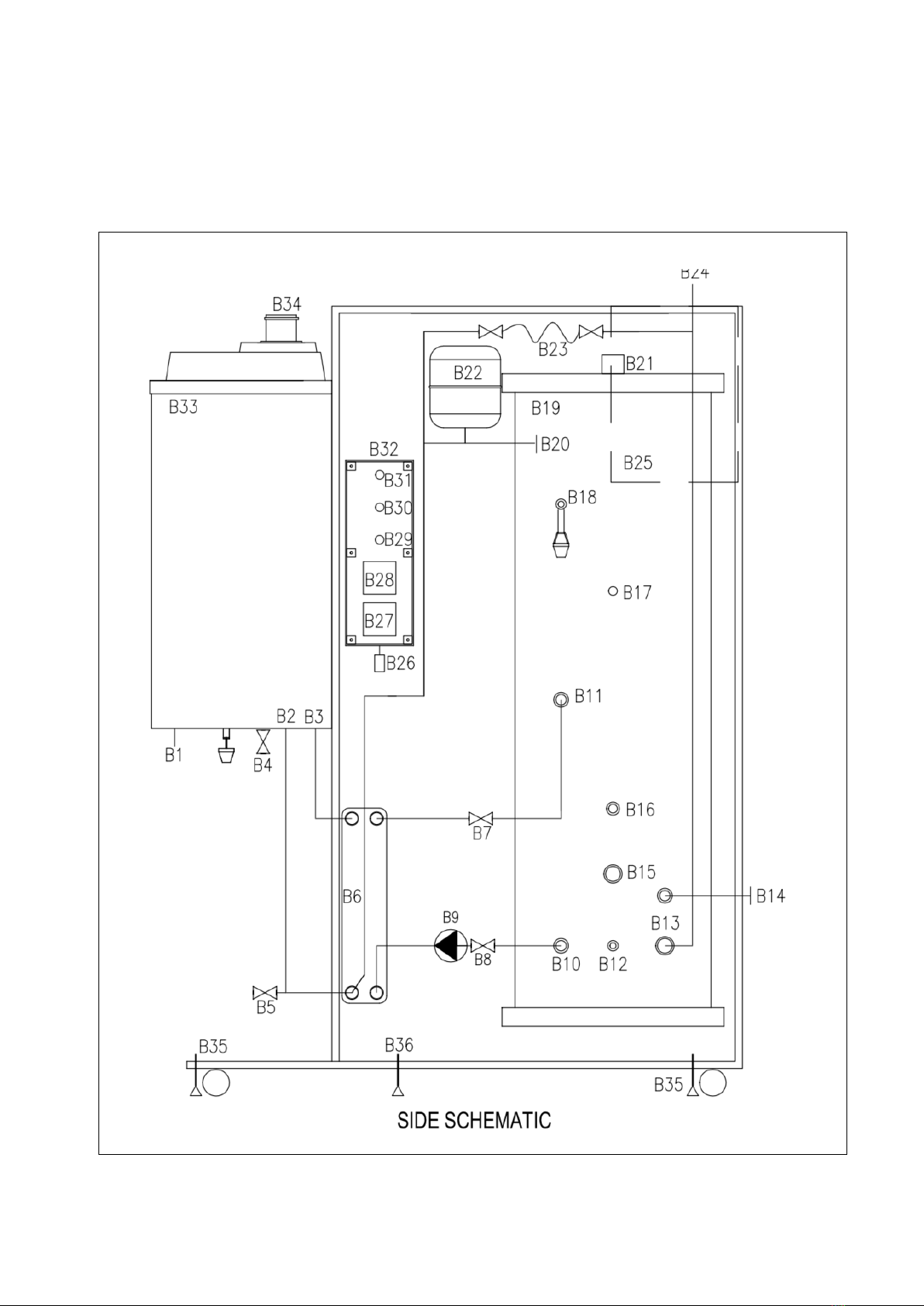
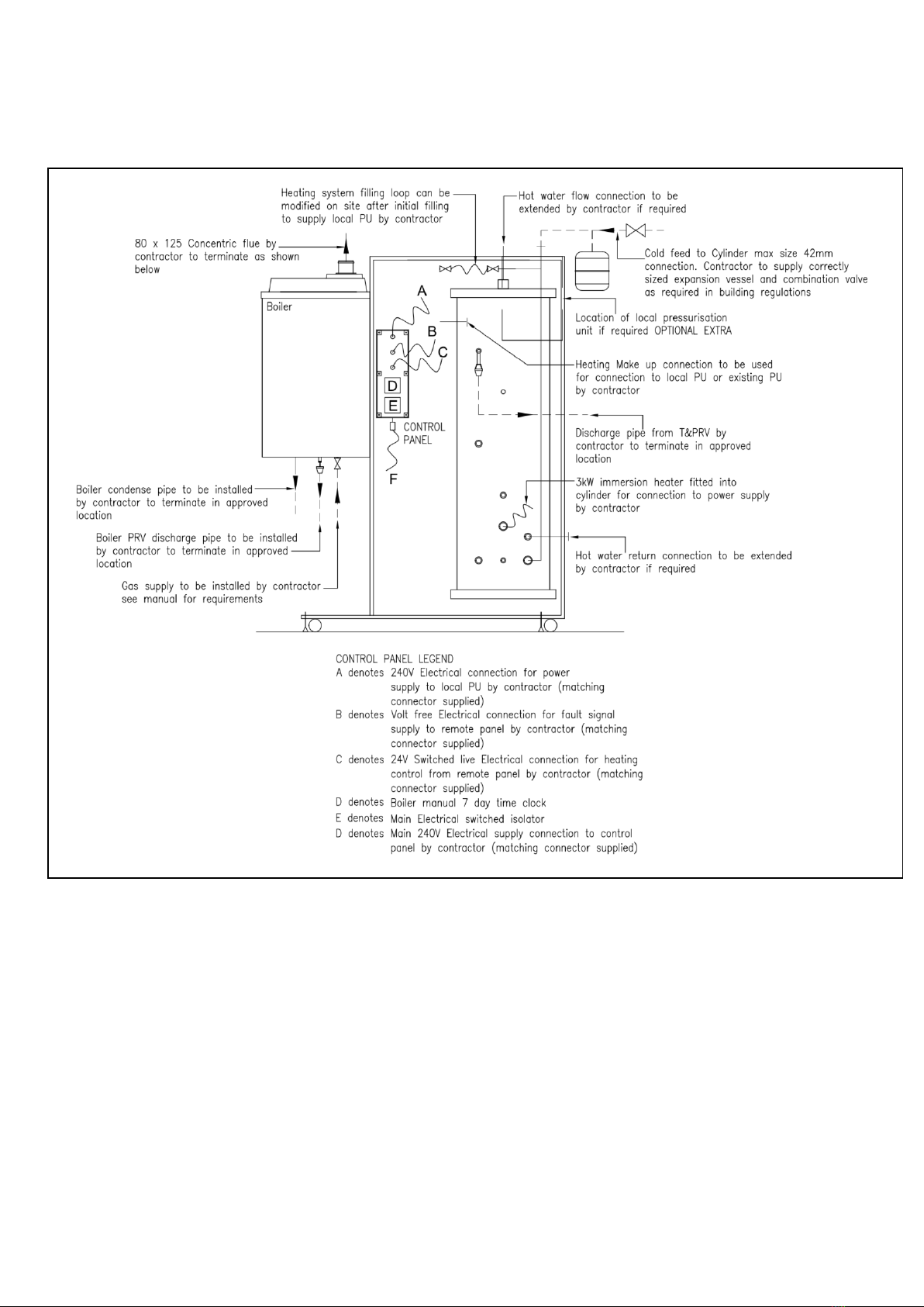
3.0 BLADE WATER HEATER SCHEMATIC LAYOUT
Blade 50,70,90,115 Water Heater Manual April 2020
5
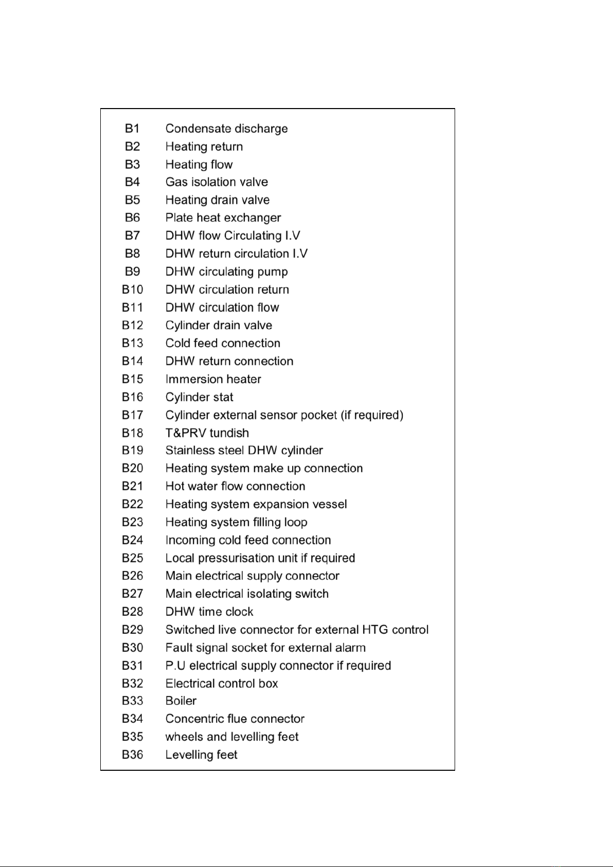
3.1 SCHEMATIC LEGEND

6
Blade 50,70,90,115 Water Heater Manual April 2020
4.0 INSTALLATION REQUIREMENT
4.1 GENERAL SITE REQUIRMENTS:
a) Flat level floor surface (<3mm per metre)
b) Gas supply –as technical data
c) Main pipework service connections –as technical data
d) 240v single phase electrical supply
e) Control wiring as required
f) Condense and pressure relief drainage
g) Concentric flues
h) Min size door opening (W)800mm x(H)2010mm
4.2 UNPACKING AND UNLOADING INSTRUCTIONS
Note: The WH050 & WH070 Blade weighs up to 240kg (empty) and up to 586kg (full). The WH090
& WH115 Blade weighs up to 267kg (empty) and up to 622kg (full). Extreme care should be taken
when moving the unit during unloading, installation and maintenance.
The unit is delivered on a pallet base and is secured using 4 x shipping brackets. To unload the unit:
4.2.1 Ensure the pallet is located on a secure, level surface as close as possible to
the installation site. Once unloaded, the Water Heater can be manoeuvred
easily on most flat, level surfaces. Do not attempt to move the unit over uneven
or rough surfaces using the built-in wheel units.
4.2.2 Remove any shipping packaging or polythene wrapping from the unit.
4.2.3 Ensure all threaded stabilising feet on the Water Heater are fully raised. The
stabilising feet are located on each wheel mount and can be raised using a
suitable flat headed spanner from below.
4.2.4 Unbolt and remove all shipping brackets. WARNING –once the shipping
brackets have been removed and the stabilising feet raised, the unit will
become mobile from this point until it is immobilised again. The Water Heater
should be physically restrained at all times. Do not discard the shipping
brackets.
4.2.5 Carefully manoeuvre the Water Heater down to the floor surface. Note: This is
a 2 to 3 person task, and extremecare should betaken to ensure that the Blade
unitdoesnotbecomeunstable during unloading.
4.2.6 Manoeuvre the Water Heater into the desired installation location. Ensure that
suitable access is available to the rear of the unit to enable connection to the
site services.
4.2.7 Whenthe unit is located correctly, lower all six stabilising feetuntil theunitis fully
immobilised. The stabilising feet are located on each wheel mount and can be
lowered using a suitable flat headed spanner from below the wheel mount.
4.2.8 With the unit immobilised in the correct position, the Blade should be fully
secured. The four shipping brackets can be used for this purpose. If used
ensure the brackets are located firmly against the lower edge of the Water
Heater frame and secured using appropriate fixings for the floor surface. It is
important that the Blade is fully secured and immobilised before proceeding
with the connection of the site services
Blade 50,70,90,115 Water Heater Manual April 2020
7
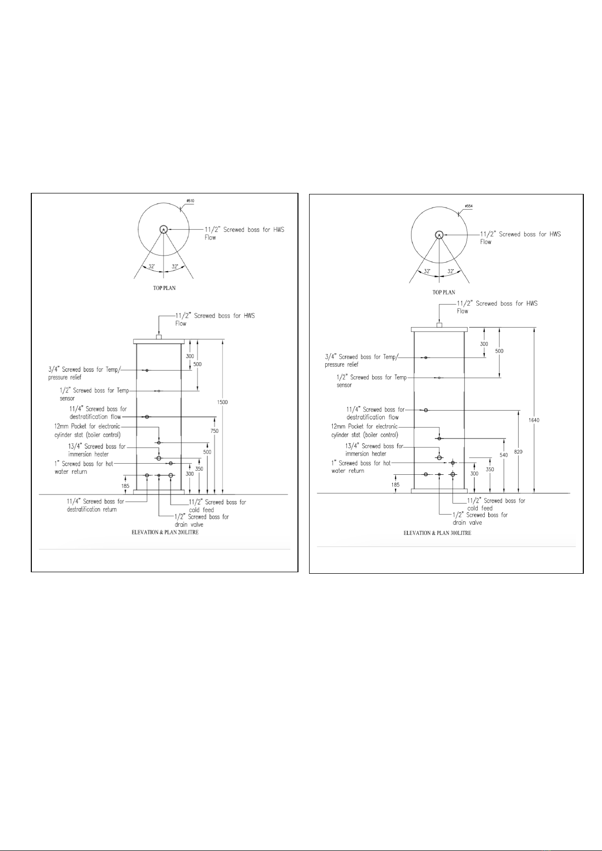
5.0 EQUIPMENT DETAILS
5.1 CYLINDER
All cylinders are purpose made to Blade specific designs by a leading manufacture, the construction is fully
welded stainless steel and approved for mains pressure or gravity systems and come complete with ERP
compliant high-density insulation and solid external powder coated finish. They come in two standard sizes 300
and 200 litres other sizes are available as special orders details on request. SEE BENCHMARK MAINTENANCE
requirements within this document which must be completed when serviced to maintain the warranty.
8
Blade 50,70,90,115 Water Heater Manual April 2020
5.2 DHW DESTRATIFICATION PUMP
Pump reference for all water heater model EVOSTA2 SAN 40-70-150
This is a low energy consumption electronic DHW pump with a Bronze pump body and wet
motor steel casing, technopolymer impeller
It has a built-in control panel on the pump facia which is factory set to suit the boiler/cylinder configuration
If modification is required these should be undertaken by a qualified engineer in accordance with the pump
manufactures instructions which are included see Appendix B
On the front of the pump casing there is a curve height indicator which will BLINK to indicate a fault see
for fault schedule below.
Alarm Description
No. of curve height blinks
EVOSTA2
2 Blinks
TRIP: loss of motor control, may be caused by incorrect parameters,
blocked rotor, disconnected phase, disconnected motor
3 Blinks
SHORT CIRCUIT: short circuit on phases or between phase and earth
4 Blinks
OVERRUN: software fault
5 Blinks
SAFETY: safety module error, may be caused by a sudden overcurrent or
other hardware faults of the board
5.3 PLATE HEAT EXCHANGER
The plate heat exchanger is manufactured from stainless steel plates brazed together in a special
Corrugation pattern to ensure a compromise between low resistance and high heat transfer. Water
treatment will be required in systems where hard water may come in contact with the plate heat exchanger.
Failure to provide adequate treatment may invalidate the warranty.
PLATE HEAT EXCHANGER SCHEDULE
WATER HEATER MODELS
WH050
WH070
WH090
WH115
Duty rating
50kW
70kW
90kW
115kW
Plate Heat Exchanger Reference
LB31-20-1”
LB31-20-1”
LB60-20-5/4”
LB60-20-5/4”
Dry Weight
3.88kg
3.88kg
6.98kg
6.98kg
Length
286mm
286mm
538mm
538mm
Width
123mm
123mm
123mm
123mm
Depth
57mm
57mm
57mm
57mm

Blade 50,70,90,115 Water Heater Manual April 2020
9
5.4 DHW TIME CLOCK PROGRAMMING
Current time and day setting
1) Press the R button to reset the timer to its default settings, activate using a pencil or similar pointed
Instrument. (pressing R will delete all stored programmes).
2) Press Y to enter function setup. (Note: if another button is not pressed within 10 seconds the display will revert to the normal
screen).
3) Use the + or - button to scroll to the clock icon (flashing) and press Y to enter the current time setting mode (hours flashing).
4) If you keep the + or - buttons pressed for more than 3 seconds, the display will enter fast scroll mode.
5) Use the + or - button to adjust the hours and press Y to confirm, minutes will flash.
6) Use the + or - button to adjust the minutes and press Y to confirm, day will flash.
7) Use the + or - button to adjust the day and press N to exit.
Programming the switching
1) There are 24 ON/OFF programmes available.
2) Press the Y button twice to enter the programming setting mode.(Note: if another button is not pressed within 10 seconds the
display will revert to the normal screen).
3) Default is programme 01 ON, this can be changed if required by pressing + or - button to scroll through the 24 ON/OFF
programmes as required, pressing the Y will confirm the programme.
4) Press the Y button to confirm programme 01 ON, hours will flash.
5) Use the + or - button to adjust the hours and press Y to confirm, minutes will flash.
6) Use the + or - button to adjust the minutes and press Y to confirm, days will flash.
7) Apart from individual days of the week, the following day combinations of multiple day blocks can be selected by pressing the + or
- buttons.
•Monday to Sunday
•Monday to Friday
•Saturday to Sunday
•Monday to Saturday
•Monday + Wednesday + Friday
•Tuesday + Thursday + Saturday
•Monday + Tuesday +Wednesday
•Thursday + Friday + Saturday
8) Select day or day blockas required and press Ybutton to confirm
9) Press the + button, this will select the programme 01 OFF,press Y to confirm.
10) Follow 4 to 7 above to set the 01 OFF programme (day or day block must be the same as programme ON).
11) If no more programmes are required, press the N button to exit.
12) If more programmes are required follow 3 above.
13) Tocancel a programme once set, press and hold the N button for more than 3 seconds when the desired programme number is
flashing i.e. to cancel programme 01 ON, press the Y button twice and hold the N button down for more than 3 seconds to delete.
Pressing the + button again will select 01 OFF.
14) Repeat 13 to delete 01 OFF. This procedure can be repeated to delete any of the 24 programmes
Timer countdown
1) Timer has a 100 hour countdown feature
i.e. the timer can be set to any period from 1 minute to 100 hours and will countdown in the ON state and turn OFF at the
end of the countdown period.
2) Press the Y button then use the + or - button to select the “down” icon on the right hand side of the display, press Y again to enter the
countdown mode.
3) Use the + or - button to adjust the hours and press Y to confirm. minutes will flash.
4) Use the + or - button to adjust the minutes and press Y to confirm and complete the countdown time setting.
5) Press the N button to start the countdown.
6) Output switched to ON during the countdown period.
7) Press the N button to pause the countdown (output switched to OFF)
8) Toresume countdown simply press the N button again.
9) Press and hold the N button for more than 3 seconds to exit the countdown function.
Manual override
1) When in normal clock mode, pressing the N button will scroll through the following switching options.
•ALWAYS ON- timer is permanently ON
•PROG- timer is in programme ON mode, will switch off at the next programme OFF time
•ALWAYS OFF- timer is permanently OFF
•PROG- timer is in programme OFF mode,will switch ON at the next programme ON time.

10
Blade 50,70,90,115 Water Heater Manual April 2020
Summer Time Setting
1) Press the Y button, then use the + or - buttons to scroll through to “summer” (flashing).
2) Press the Y button again to access the summer time setting.
3) Press the + or - button to change between summer on or off.
4) Press Y to confirm summer setting, time will advance 1 hour.
5) A “SUMMER” icon will appear in the display.
6) Use the same procedure to remove the “SUMMER” icon when reverting to GMT in the winter.
Random Setting
The random setting allows the timer to switch ON and OFF with a random delay of between 2 and 32 minutes. This function will only
operate if one or more programmes have been programmed into the timer.
1) Press the Y button, then use the + or - buttons to scroll through to “RANDOM” (flashing).
2) Press the Y button again to access the random setting.
3) Pressing the + or - buttons will toggle the random icon on and off.
4) Press the Y button to confirm random function.
5) A “RANDOM” function icon will appear in the display.
6) Timer will now operate in the random mode
7) To cancel random feature use the procedure above to remove the “RANDOM” icon from the display.
Reading your programmed times
1) Press Y button twice to enter programme mode.
2) Press the + or - buttons to scroll through the 24 ON/OFF programmes to check settings.
3) Press the N button to exit and revert to clock mode.
Reading your programmed times
1) Press Y button twice to enter programme mode.
2) Press the + or - buttons to scroll through the 24 ON/OFF programmes to check settings.
3) Press the N button to exit and revert to clock mode.
Reset
Pressing the reset button R with a pencil or similar will reset all programmed times and set time of day to zero.
5.5 DHW CYLINDER THERMOSTAT
User explanation
A cylinder thermostat switches on and off the heat supply from the boiler to the hot-water cylinder. It works by sensing the
temperature of the water inside the cylinder, switching on the water heating when the temperature falls below the thermostat
setting, and switching it off once this set temperature has been reached. The water heating will not work if a time switch or
programmer has switched it off. The cylinder thermostat will have a temperature scale marked on it, and it can be adjusted to
the chosen temperature, then left to do its job. The thermostat must be designed to kill off harmful bacteria in the water.
Raising the temperature of the stored hot water unnecessarily results in wasted energy and increases the risk of scalding.
Dual cylinder thermostats combine both the controller and the limit thermostats into one common unit. If you have a boiler
control thermostat, it should always be set higher than that of the cylinder thermostat. Inmost boilers, a single boiler thermostat
controls the temperature of water sent to both the cylinder and radiators, although in some there are two separate boiler
thermostats.
Important Note
As a safety feature, when first connected the Electronic Dual Cylinder Thermostat will call for heat until the hot water cylinder
has reached 61°C and held that temperature for one hour. During this time there will be a live output to the and therefore to
the boiler and the pump
The Electronic Dual Cylinder Thermostat
The hot water can be stored at any desired temperature between 25°C and 65°C, with the confidence that the weekly
automatic one hour “boost” to above 60°C kills any legionella bacteria, resulting in substantial energy saving.
The LCD display shows the current water temperature and the user defined water temperature, while the red LED indicates
that the unit is calling for heat. The sensitive electronic sensors operate at a far greater accuracy than conventional oil filled
mechanical dual thermostats, and do not need physical contact unlike traditional dual thermostats.
The large dial makes it easy to set the required controller temperature (between 25°C and 65°C). While the second (limit)
safety thermostat is pre-set to 80°C with a concealed manual reset, to comply with building regulations.

Blade 50,70,90,115 Water Heater Manual April 2020
11
Boiler Setting
To ensure the elimination of Legionella Bacteria in the Hot Water Cylinder, at least once a week the Cylinder should be
heated to 61°C. This is carried out automatically by the Cylinder thermostat. The Boiler Thermostat (output temperature) must
therefore be set to maximum and USER should be made aware that once a week the hot water will be warmer following the
automatic “weekly boost”. We also therefore strongly recommend the use of a thermostatic mixing valve (TMV), these blend
hot water with cold water to ensure constant safe shower and bath outlet temperatures, preventing scalding.
Holiday Switch
This is the black button located under the display. Press and hold the holiday switch for a minimum of 10 seconds until you
hear an audible click, and this switches the cylinder thermostat off completely so there is no water heating and no weekly
“boost” heating. This feature should only be used when the property is vacant for extended periods and there is no requirement
for water heating or for the weekly “boost”. Pressing and holding the holiday switch again (for a minimum of 10 seconds until
you hear an audible click) will restart the cylinder stat, the display will show the cylinder temperature and the weekly “boost”
will immediately start and recur every 1-7 days depending on the user set position at the same time.
Adjusting and Resetting the Cylinder Thermostat
Adjust the dial to show the desired hot water temperature on the display, between 25°C to 65°C. The lower the temperature,
the less chance of scalding and the more energy saving. The Cylinder temperature will be factory set at 61°C. If the system
should overheat, the cause must be determined and resolved by a suitably qualified person. In the event of an overheat, the
thermostat cuts out automatically. THE RESET FOR THE OVERHEAT THERMOSTAT IS LOCATED UNDER THE
ADJUSTMENT DIAL.
Adjusting the 1 Hour Boost
The Cylinder thermostat has user defined settings where the duration of the Legionella Override can be adjusted from 1 to 7
days or completely disabled to operate as a conventional Dual Cylinder Thermostat.
1. To disable/adjust the legionella boost turn the unit off by pressing and holding down the HOLIDAY button until an audible
click is heard and the red LED turns off.
2. Release the button and after approx. 10 seconds press and hold the HOLIDAY button again. After 5 seconds the red LED
will light up and an audible click is heard, keep the HOLIDAY button pressed for a further 5 seconds until the LCD display
flashes.
3. Release the button and use the HOLIDAY button to choose between disabling the override (OF) or setting the delay
between the overrides from 1 –7 day
12
Blade 50,70,90,115 Water Heater Manual April 2020
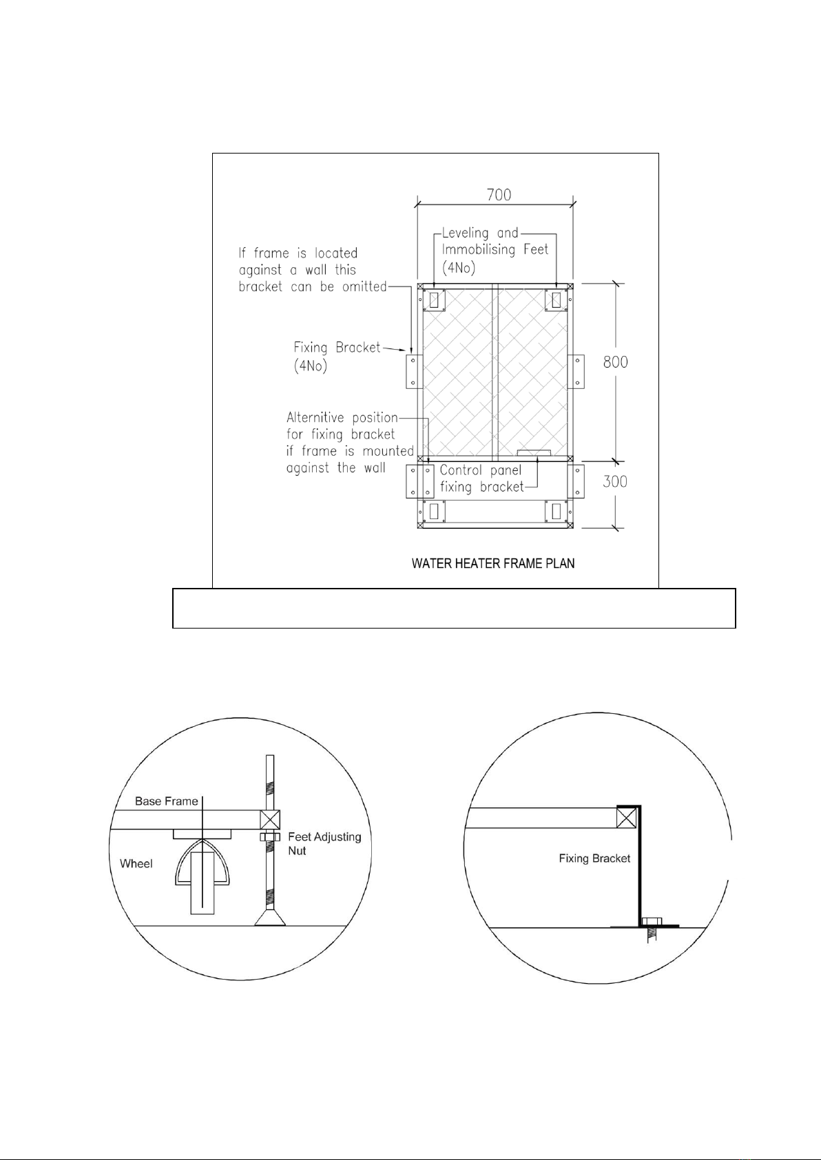
6.0 FIXING DETAILS
Frame Levelling and Immobilisation Detail Frame Fixing Bracket
fixing bolt to suit
structure not supplied
Base Plan for NWH050, NWH070, NWH090 & NWH115 Showing fixing details

Blade 50,70,90,115 Water Heater Manual April 2020
13
7.0 GENERAL SERVICES REQUIREMENTS
7.1.1 For site services connection information, refer to the connection
diagrams. All connections should be made in accordance with current
building regulations.
7.1.2 The electrical and controls connections should be made in an approved
manner, and the unit should be earthed in accordance with building
regulations.
7.1.3 Flues should be extended from the spigot connection on the boiler. All
fittings should have joints made in accordance with the instructions.
The whole flue system should besubjecttoa VISUALinspectionduring
testing and terminate with an approved vent cowl. Only approved flue
components should beused withthis product.The flue should be tested
in accordance with current Gas Safe requirements.
7.1.4 It is recommended that the heating system is treated with an approved
scale inhibitor and DHW services disinfected in accordance with
current regulations.
7.1.5 Condense traps within the boiler and at rear of heating servers to be
filled with water via the boiler prior to the boiler being fired.
7.1.6 Water pressures must not exceed that stated on the cylinder and boiler
data label. An approved pressure regulating valve must be used if
required.
7.1.7 For sealed heating and domestic water services the correct size
expansion vessel must be installed to protect the system from the
excess pressure created by waterexpansion.
7.1.8 All pumps within Water Heater should be vented during commissioning
via vent screw on front of pumps.
7.1.9 Automatic air release valves must be installed at the high point on the
system where necessary.
7.1.10 The boiler within the Water Heater should be commissioned by a
competent engineer in accordance with the manufacturer’s instructions
supplied.
7.1.11 The Boiler flow temperatures should be set via the boiler control panel
in accordance with Appendix A. All other controls if fitted are via the
external control panel notsupplied.
7.1.12 All mechanical unions and nuts should be checked for tightness as they
can loosen in transportation.
7.1.13Condensate and T and P relief valve should terminate in suitablelocations.
7.2 BLADE LOCATION
The Blade unit is not suitable for external installation unless it is within a purpose designed weatherproof
building. The Blade may be installed in any room or internal space so long as it is fitted in accordance
with ventilation requirement, Institute of Gas Engineers Guide for gas installations and correct IEE Wiring
BS7671 Regulations. See pages 13-14 for maintenance access requirements.
7.3 FROST PROTECTION
The boiler within the Blade server is fitted with a frost thermostat that activates the pump and burner
when the system water temperature in the boiler falls below 3°C
14
Blade 50,70,90,115 Water Heater Manual April 2020
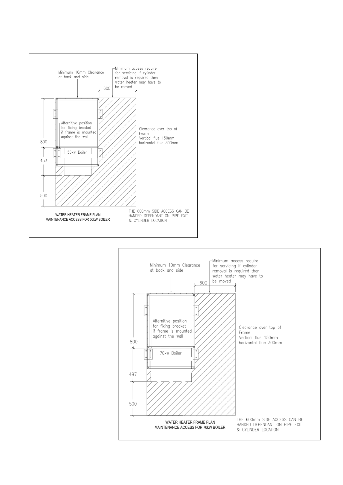
8.0 MAINTENANCE AND SERVICING CLEARANCES
Blade 50,70,90,115 Water Heater Manual April 2020
15
8.0 MAINTENANCE AND SERVICING CLEARANCES
16
Blade 50,70,90,115 Water Heater Manual April 2020
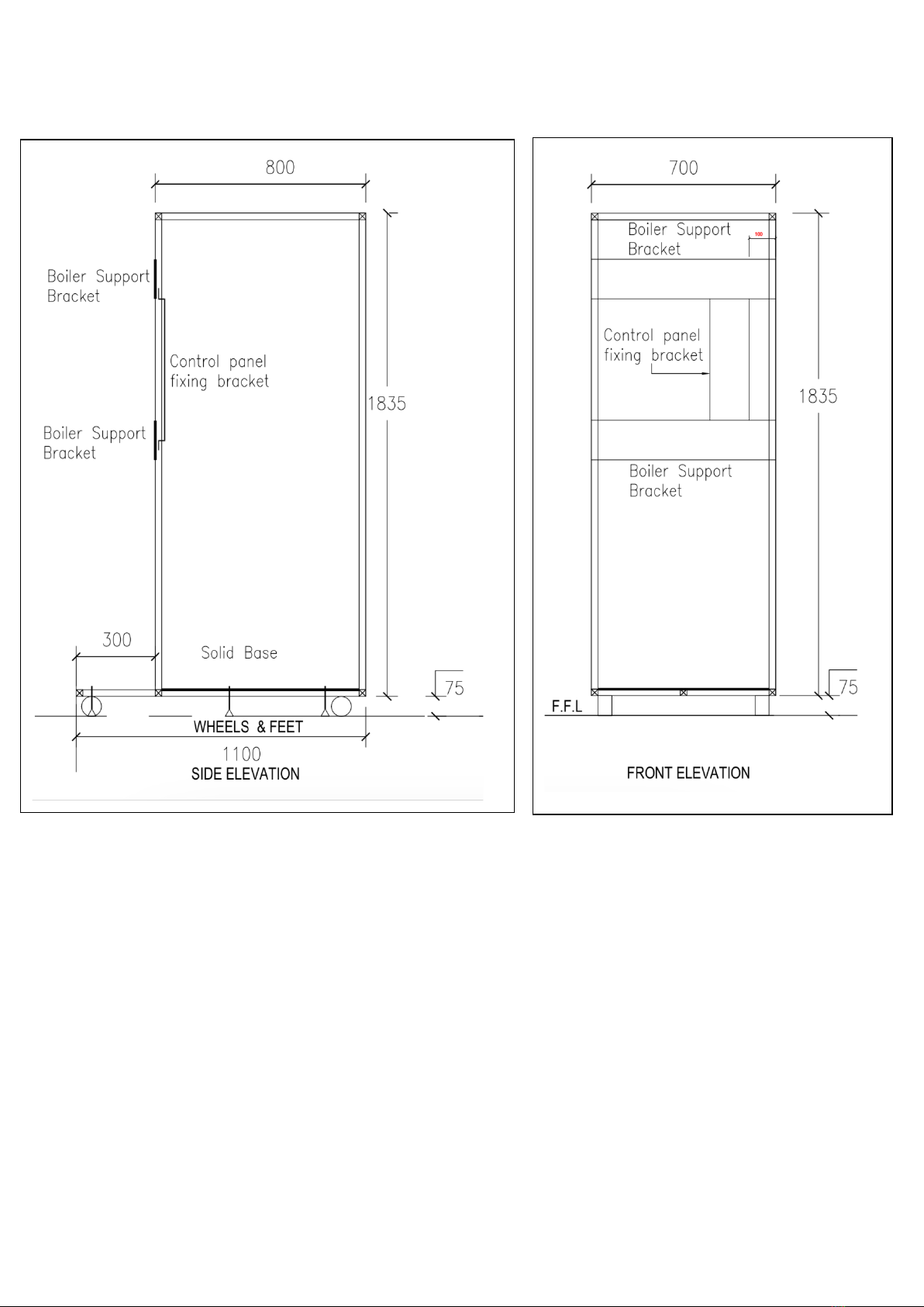
9.0 FRAME DETAILS
Blade 50,70,90,115 Water Heater Manual April 2020
17
10.0 INSTALLATION SCHEMATIC LAYOUT
18
Blade 50,70,90,115 Water Heater Manual April 2020
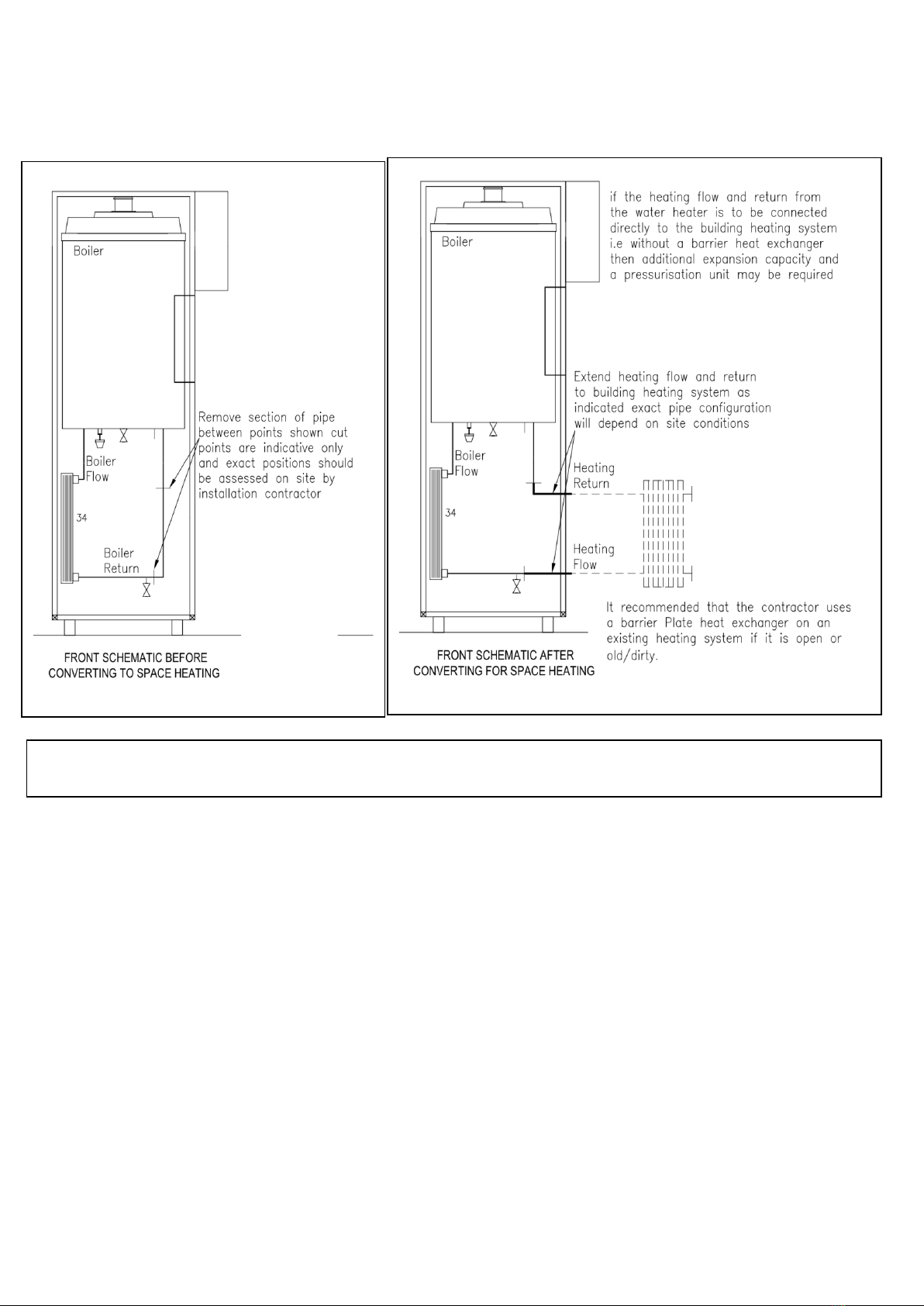
11.0 CONVERSION TO SPACE HEATING DETAILS
The Water Heater can be supplied factory converted and configured to supply both DHW and space heating
on request
This manual suits for next models
7
Table of contents
Popular Water Heater manuals by other brands


HTP
HTP Hydra Smart RT-199 User's information manual

Immergas
Immergas SOL 750 V2 Instructions for installation and use

GSW
GSW 110 Installation manual and owner's guide

Rheem
Rheem Everhot 2A1 Series Owner's guide and installation instructions

Modena
Modena Tondo Series User manual book

Rheem
Rheem 18 Owner's guide & installation instructions