HG-CF-1101 Rev. C – 19.05.06 Page 12
IMPORTANT ! Read these instructions completely, before installation and start-up. It is the responsibility of the purchaser to retain
this manual for reference. Failure to comply with the recommendations stated in this manual will damage the pump, and void
factory warranty.
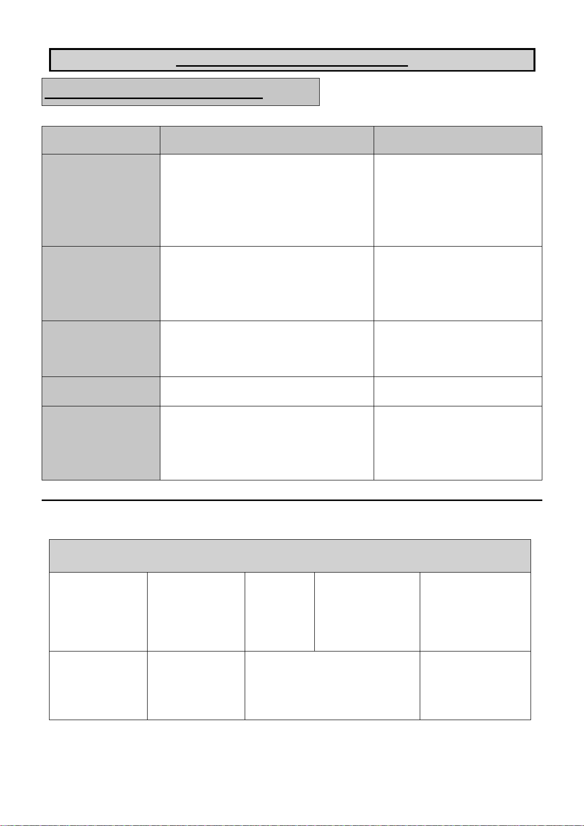
SERVICE
The following sections give a general
overview on how to service all models of
BLAGDON Diaphragm Pumps. For
details on individual part numbers,
quantities, materials, etc., please consult
the parts list supplied with the pump.
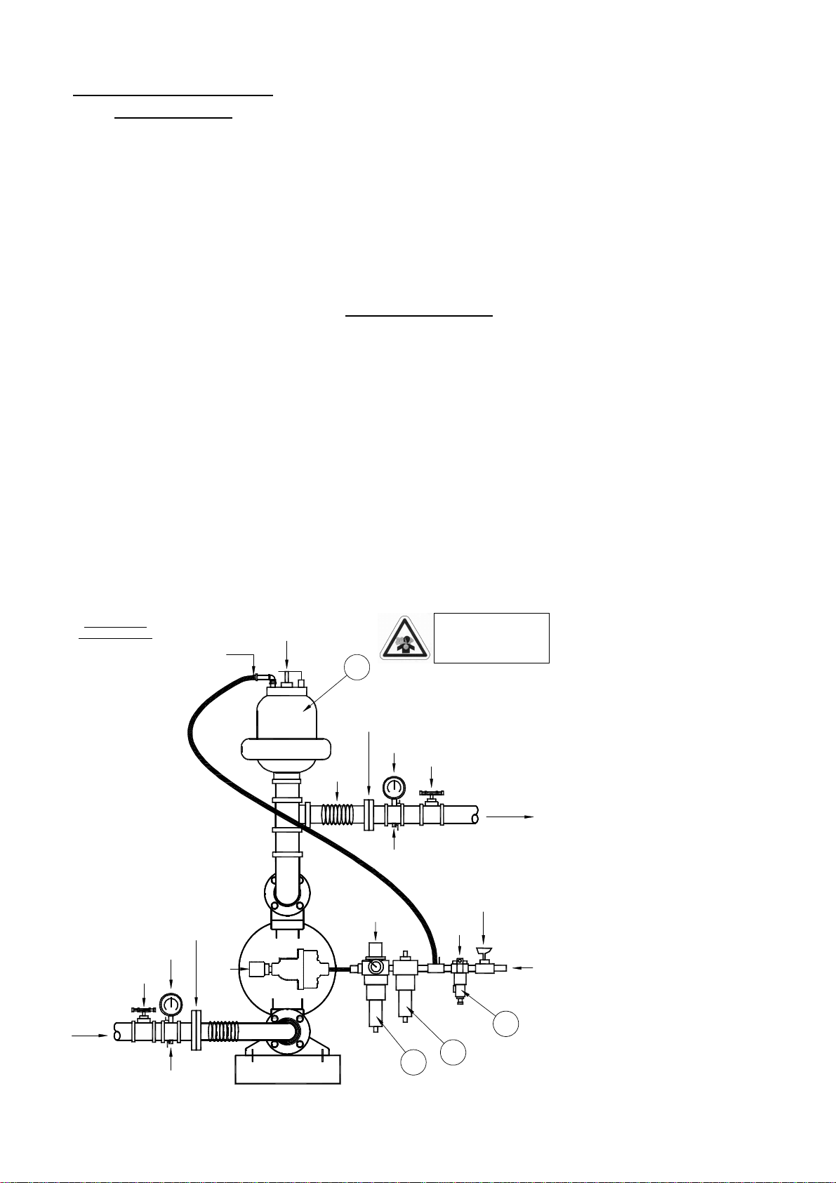
NOTE : Before commencing any
service or maintenance work on the
pump, ensure that the air supply has
been disconnected or isolated.
AIR SIDE OVERHAUL
PNEUMATIC TYPE Remove the 4
screws securing the valve block to the
valve chest, together with any associated
gaskets or seals.
Remove slide valve plate & slide valve
from the valve block assembly. Clean all
parts thoroughly and inspect for
excessive wear, replacing where
necessary.
The slide valve and valve plate contact
faces should be flat and free from
scratches. A light polishing on a flat
surface with a fine abrasive paper will
remove most scratches.
If excessive wear is suspected in the
valve block bore or valve carrier, remove
the valve block plugs and withdraw the
valve carrier. Check valve block plug o-
rings for wear or attack & replace where
required.
Clean the valve carrier & valve block
bore with white spirits to remove any oil
films.
NOTE : The nominal diametrical
clearance between the valve carrier and
the valve block block bore should be
0.05 - 0.09mm. A clearance in excess of
this will cause the valve system to run
erratically.
Apply a light grease to the valve block
plug O-rings when re-assembling into the
valve block bore. Any damage to the O-
ring may cause the valve system to
malfunction.
Re-assemble the valve block assembly &
re-torque in accordance to the settings
shown in the parts list.
In the event of a complete air-side
overhaul, the pump should be dis-
assembled down to the centre section
assembly as described later in the “Wet-
Side Overhaul” section.
With the valve block assembly
dismantled, remove the inner covers
where appropriate.
A careful note of the position of all
related seals and gaskets should be made
to facilitate re-assembly.
Remove diaphragm shaft bushes, where
appropriate, and check all seals and ‘O’
rings for wear or damage. If worn,
replace immediately.
NOTE:- The integrity of the diaphragm
shaft seals is essential for the correct
functioning of all pneumatically
actuated valve systems.
Check the diaphragm shaft for excessive
wear as this will result in premature seal
failure. Replace as required. Lubricate
all components and re-assemble as
detailed above, in reverse order. Ensure
the correct position of all components
detailed in all sectional assembly
drawings.
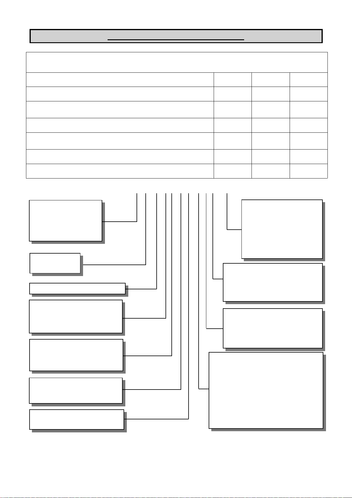
WET-SIDE OVERHAUL
REPLACING BALL VALVES
Remove discharge manifold from pump
assembly together with associated valve
balls, seats and ‘O’ rings.
NOTE :- The orientation of the valve
seat relative to the valve ball should be
noted as incorrect positioning may
result in a performance loss.
Turn pump through 180oand remove the
suction manifold. Clean and inspect the
components. Check for any wear or
damage and replace as required.
NOTE :- Ball or valve seat wear may
result in loss of performance and
suction lift.
Re-assemble the valve balls/seats and
ensure manifolds are adequately torqued
to the settings shown in the parts list.
REPLACING DIAPHRAGMS
Remove both suction and discharge
manifolds as detailed in the previous
section, removing all ball valves, seats
and ‘O’ rings.
Loosen and remove both outer covers
from the pump assembly. The
orientation of the covers should be noted
so as to facilitate re-assembly.
Holding one of the frontplates in a vice,
(‘soft jaws’ should be fitted), or with an
adjustable spanner, loosen and remove
the frontplate from the opposite end.
Remove the diaphragm, backplate and
bumpstop from diaphragm shaft.
Carefully withdraw the diaphragm shaft
from the centre section and hold the free
end in a vice, holding between the flats
machined on the end. Loosen and
remove the frontplate and remove the
diaphragm together with backplate and
bumpstop (where fitted).
NOTE :- Care should be taken with all
plastic, coated and hygienic pumps, so
that the surface of the frontplate is not
damaged.
Thoroughly clean all parts and check for
wear, damage, swelling, cracking,
delamination and chemical attack.
Replace components where required.
NOTE :- Rubber diaphragms should be
replaced if they are worn to such an
extent that the fabric re-enforcing is
evident on the surface of the diaphragm.
For pumps fitted with PTFE diaphragms,
a light coating of grease should be
applied to the back-up diaphragm prior to
re-assembly.
Before re-assembly, it is advisable to
check the condition of the diaphragm
shaft seal/’O’ rings for wear or attack. If
either is evident, it is recommended that
they be replaced.
Assemble the diaphragms onto the shaft
in a reverse sequence to their removal.
Care should be taken as to the orientation
of the diaphragm relative to the front and
back plates. All diaphragms have “AIR
SIDE” moulded onto one side. The
backplate must be fitted adjacent to the
AIR SIDE of the diaphragm.
On all pumps fitted with stainless steel
fasteners, including clamp bands, it is
recommended that anti-seize paste is
applied to the threads. Bolted assemblies
should be torqued to the settings shown
in the parts list. Please refer to the dia-
gram on page 11 for the correct se-
quence for re-assembly of the Outer
Covers. (This is very important for
reliable sealing). Re-assemble manifolds
in reverse of the sequence described ear-
lier.