DRD 700 Quad Multistream Processor
Rev. D www.blankom-digital.de Page 3 (26)
Table of Contents
IMPORTANTNOTES!.....................................................................................................................................................2
INSTALLATIONNOTES...................................................................................................................................................2
TABLEOFCONTENTS.....................................................................................................................................................3
GENERALDESCRIPTION.................................................................................................................................................4
INPUT......................................................................................................................................................................................5
ASIINTERFACE..........................................................................................................................................................................5
WIDE‐RANGEPOWERSUPPLYUNIT:...............................................................................................................................................5
TESTEQUIPMENT.......................................................................................................................................................................5
SOFTWAREOPTIONS...................................................................................................................................................................5
ORDERINGCODES.........................................................................................................................................................6
CONTROLWITHDISPLAYANDNAVIGATIONWHEEL......................................................................................................7
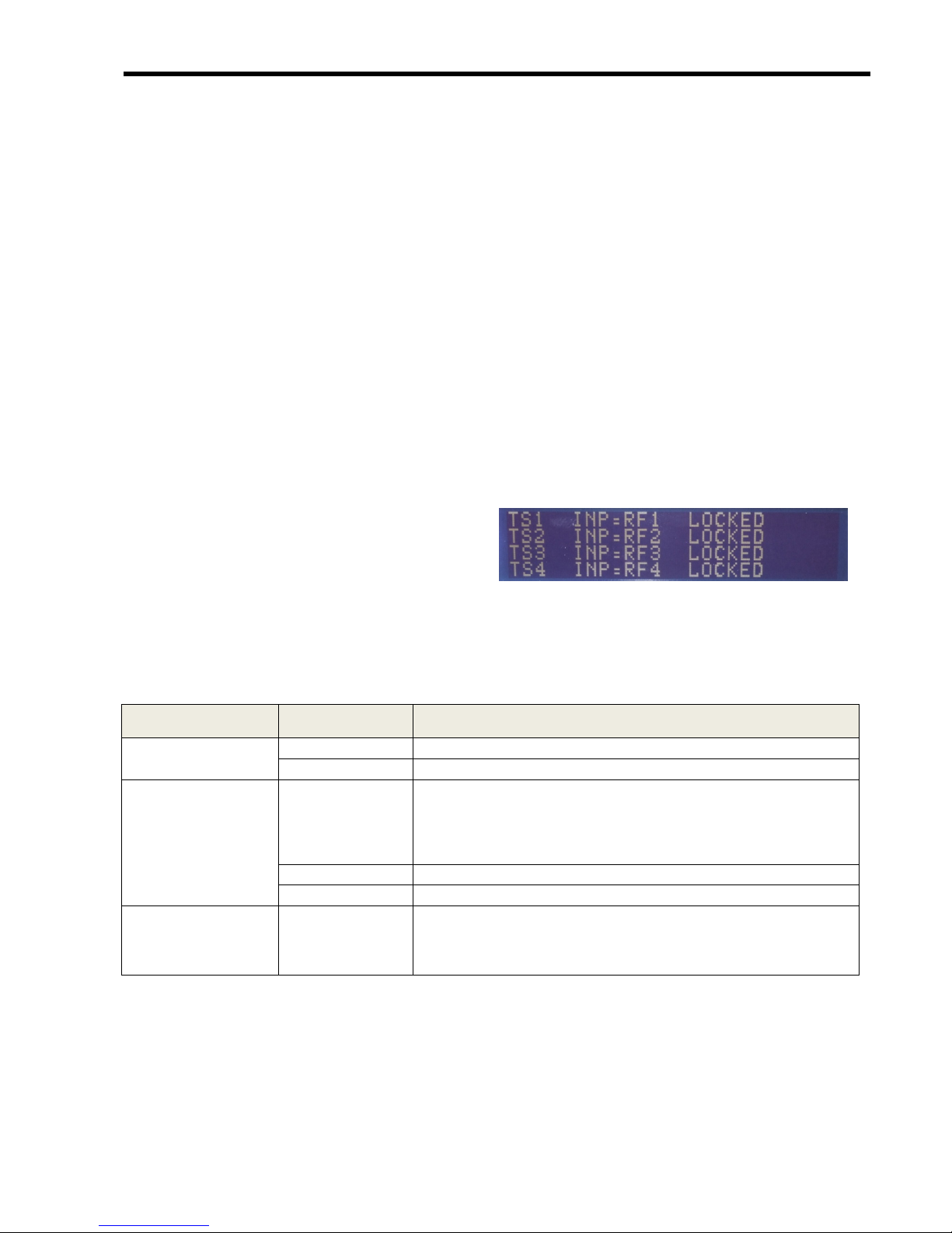
OPERATIONDISPLAY...................................................................................................................................................................7
DESCRIPTIONOFMENU...............................................................................................................................................................7
CONTROLWITHWEBSERVER........................................................................................................................................8
HOME......................................................................................................................................................................................8
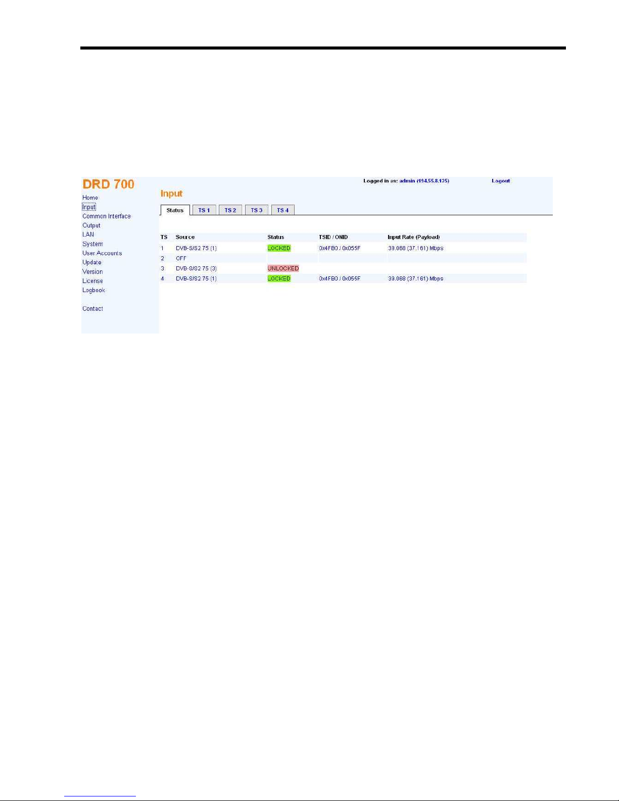
INPUT......................................................................................................................................................................................9
IPINPUT(OPTION):....................................................................................................................................................................9
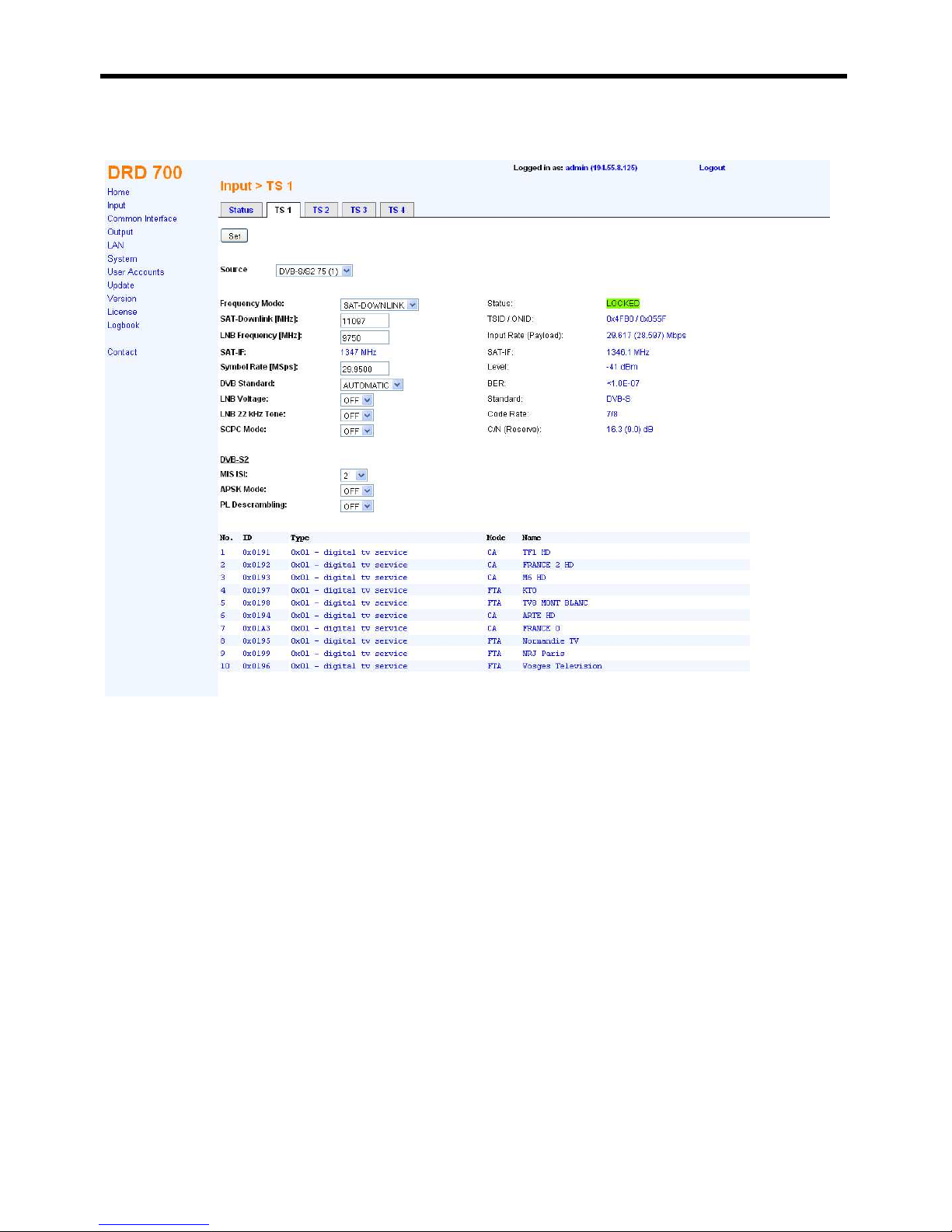
INPUT‐DVB‐S/S2(OPTION)......................................................................................................................................................10
COMMONINTERFACE................................................................................................................................................................11
BISSDECRYPTION....................................................................................................................................................................12
MPTSOUTPUT.......................................................................................................................................................................14
SPTSOUTPUT.........................................................................................................................................................................14
LAN......................................................................................................................................................................................15
LAN‐SNMP...........................................................................................................................................................................16
LAN‐TELNET(OPTION).............................................................................................................................................................17
SYSTEM..................................................................................................................................................................................17
USERACCOUNTS......................................................................................................................................................................19
UPDATE.................................................................................................................................................................................20
VERSION................................................................................................................................................................................21
LICENSE..................................................................................................................................................................................21
CONNECTIONS............................................................................................................................................................22
TECHNICALDATA........................................................................................................................................................23
HISTORY.....................................................................................................................................................................25