Blankom IRD-6300 User manual

BLANKOM IRD-6300 HD IRD
User Manual

BLANKOM IRD-6300 HD IRD User Manual
BLANKOM_IRD-6300_User_Manual.docx - 2 -
Inhalt
Chapter 1 Product Outline.........................................................................................................................3
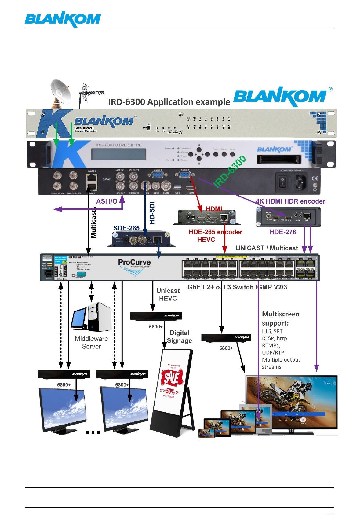
Application Example .................................................................................................................................4
Features ...................................................................................................................................................5
Block diagram...........................................................................................................................................5
Specifications:...........................................................................................................................................6
Appearance and description......................................................................................................................9
Chapter 2 Installation Guide....................................................................................................................10
1.1. Accessories...................................................................................................................................................10
IRD-6300 HD IRD Satellite Receiver Signal Cable Connections:..................................................................12
Chapter 3 Operation ...............................................................................................................................14
Keypad Function Description:.......................................................................................... 14
System config: ........................................................................................................................................27
General Settings for the DECODER & Output values: ................................................................................28
Cross connection to the CAM-CARD-Menu:..............................................................................................31
MPTS-Output:.........................................................................................................................................31
MUX-Mode:............................................................................................................................................32
SPTS-Outputs:.........................................................................................................................................35
Transmit:................................................................................................................................................37
Now we crosscheck what we are getting out of the box: ..........................................................................38
BISS Descrambling (Basic Interoperable Scrambling System) ....................................................................41
Mode 1............................................................................................................................. 42
Mode E............................................................................................................................. 43
Chapter 5 Troubleshooting......................................................................................................................44
Chapter 6 Packing List .............................................................................................................................44
General notes about Streams: .................................................................................................................45
Multicast streams: ..................................................................................................................................45
Registered port................................................................................................................ 47
RTP:........................................................................................................................................................48
ANNEX MPEG..........................................................................................................................................50
ANNEX Channel Plan (CATV channel plan) ...............................................................................................51
Appendix DB...........................................................................................................................................52
Appendix A.............................................................................................................................................55
Safety instructions ..................................................................................................................................56
Sicherheitshinweise ................................................................................................................................58
Installation guide for F-connectors: .........................................................................................................60
Installation and safety instructions / Montage und Sicherheitshinweise...................................................61
Important notes: / Zur Beachtung ...........................................................................................................62
Document History:..................................................................................................................................62
Contact:..................................................................................................................................................63

BLANKOM IRD-6300 HD IRD User Manual
BLANKOM_IRD-6300_User_Manual.docx - 3 -
Chapter 1 Product Outline
Outline
This BLANKOM IRD-6300 HD IRD receives Transponder RF-signals from the installed tuner (DVB-S/S2/S2X, DVB-C,
DVB-T/T2, ISDB-T, ATSC-T optional), ASI and IP-Input sources. After demodulating, de-scrambling, re-multiplexing
and decoding, it gives content out through various video/audio interfaces (HDMI, CVBS, 3G-SDI) or ASI or IP.
The BLANKOM IRD-6300 HD IRD is featured with two CAM/CI slots and BISS which supports to descramble
encrypted Tuner, ASI or IP signals.
Statement:
Text and pictures herein are subject to changes w/o notifications.
The user manual will be updated in real time without special notice.
This user manual is provided only as a reference guide for technicians as examples.
Default Values
The factory default administrator account: admin
The factory-default user password: admin
The factory default IP address: 192.168.0.136 NM 255.255.255 GW 192.168.0.1
Set the administrator’s computer IP as: 192.168.0.* to avoid IP conflicting with the units own IP address 192.168.0.136.
192.168.0.*: use an IP setting “*” in the number range 2-254 and except the units default IP.
Remark: .0 is often the network router, .1 often the Gateway of the used router, .255 might be a network broadcasting
address.
Please change these account settings according to your local policy and network. -> Do not forget to safe and backup the
configuration by Web-Interface and its related system-sub-menu.

BLANKOM IRD-6300 HD IRD User Manual
BLANKOM_IRD-6300_User_Manual.docx - 4 -
Application Example

BLANKOM IRD-6300 HD IRD User Manual
BLANKOM_IRD-6300_User_Manual.docx - 5 -
Features
•Demodulator + descrambler +re-mux+ decoder in one box
•1 or 2 Tuner inputs (DVB-C/T/T2/S/S2/S2X/ATSC-T/ISDB-T optional) for option
•2 ASI & 16 IP UDP/RTP input for re-mux
•Support 1ch HDMI/CVBS/3G-SDI video out (SDI1 and SDI2 mirrored out)
•Support 1ch or 2ch Audios out for option
•SupportHD/SDMPEG2,MPEG4AVC/H.264,HEVC/H.265and
•AVS/AVS+ decoding
•Support MPEG 1 Layer II, LC-AAC, HE-AAC, HE-AAC V2, Dolby Digital/Dolby Digital Plus decoding and
AC3 passthrough
•IP (1 *MPTS & 16* SPTS) output over UDP and RTP/RTSP; 2 ASI mirrored out as a copy of the IP MTPS
•Each CAM can decrypt multiple programs from Tuner/ASI/IP
•BISS descrambling (Up to 120Mbps)
•Support CC (EIA608, EIA708) & Teletext (Applicable for SDI port)
•Support maximum 128 PID mapping per input
•LCD/Keyboard and web-based NMS management
•Updates via web
Block diagram

BLANKOM IRD-6300 HD IRD User Manual
BLANKOM_IRD-6300_User_Manual.docx - 6 -
Specifications:
Input
1 or 2 *Tuner for option, F type, (DVB-C/T/T2/S/S2/S2X/ATSC-T/ISDB-T
optional as per order)
2*ASI input for re-mux, BNC interface
16*IP input for re-mux (UDP/RTP), RJ45
Tuner
Section
Multi-mode
tuners
switchable
Cable
Input Frequency
60~890 MHz
Standard
DVB-C/J.83A,
J.83C
J.83B
Constellation
16/32/64/128/256
QAM
64/256 QAM
Symbol rate
1.0~7.0Msps
DVB-T
Input Frequency
60~890 MHz
Constellation
QPSK, 16QAM, 64QAM
Bandwidth
6/7/8 M
DVB-T2
Input Frequency
60~890 MHz
Constellation
QPSK, 16QAM, 64QAM, 256QAM
Bandwidth
5/ 6/7/8 M
ISDB-T
Input Frequency
60~890 MHz
Constellation
DQPSK, QPSK, 16QAM, 64QAM
Satellite
DVB-S
Input Frequency
950~2150MHz
Symbol rate
0.5~45Msps
Signal Strength
- 65- -25dBm
FEC
1/2, 2/3, 3/4, 5/6, 7/8
Constellation
QPSK
DVB-S2
Input Frequency
950~2150MHz
Symbol rate
QPSK/8PSK/16APSK: 0.5~45Msps
32APSK: 0.5~40Msps;
FEC
QPSK: 1/2, 3/5, 2/3, 3/4, 4/5, 5/6, 8/9,
9/10
8PSK: 3/5, 2/3, 3/4, 5/6, 8/9, 9/10
16APSK: 2/3, 3/4, 4/5, 5/6, 8/9, 9/10
32APSK: 3/4, 4/5, 5/6, 8/9, 9/10

BLANKOM IRD-6300 HD IRD User Manual
BLANKOM_IRD-6300_User_Manual.docx - 7 -

BLANKOM IRD-6300 HD IRD User Manual
BLANKOM_IRD-6300_User_Manual.docx - 8 -
Environment
0~45℃(work);-20~80℃(Storage)
Power requirements
100~240VAC, 50/60Hz
Power consumption
20W
Order Guide
Please specify both Tuner Input and Audio out channel options when you place order:
Tuner Input
Option 1
1*DVB-S/S2/S2X
tuner
Option 2
1*DVB-C/T/T2/ISDB-T
tuner
Option 3
1*ATSC-T tuner
Option 4
2*DVB-S/S2/S2X
tuner
Option 5
2*DVB-C/T/T2/ISDB-T
tuner
Option 6
2*ATSC-T tuner
Option 7
1*DVB-S/S2/S2X tuner + 1*DVB-C/T/T2/ISDB-T tuner
Option 8
1*DVB-S/S2/S2X tuner + 1* ATSC-T tuner
Option 9
1*DVB-C/T/T2/ISDB-T tuner + 1*ATSC-T tuner
Audio Out
Channel
Option 1
1*Audio out
Option 2
2*Audio out

BLANKOM IRD-6300 HD IRD User Manual
BLANKOM_IRD-6300_User_Manual.docx - 9 -
Appearance and description
Front Panel Illustration:
1
2
3
4
Rear Panel Illustration
12 4 5 7 8 9 10 11
1
2 RF signal inputs and loop-through 1 & 2
2
NMS port for management
3
Data port for IP in and out
4
ASI input Port for re-mux
5
ASI mirrored output ports
6
Analog audio output interface
7
SDI video/audio output interfaces, SDI2 out as mirror of SDI1
8
Composite video output interface (CVBS)
9
USB upgrade port
10
HDMI video/audio output interface
11
Power switch/Fuse/Socket/ Grounding Wire
1
monitor LCD display for device control and configuration
2
Indicators Area (to indicate locking status of tuner, ASI and IP
input; Decoder: to indicate the decoding status)
3
Up/Down/Left/Right Buttons
Enter Key Menu Key Lock Key
4
CAMs /Smart card slots A & B

BLANKOM IRD-6300 HD IRD User Manual
BLANKOM_IRD-6300_User_Manual.docx - 10 -
Chapter 2 Installation Guide
Accessories
When you open the package of the device, it is recommended to check delivered items according to the packing
list. Normally it should include the following items:
•BLANKOM IRD-6300 HD IRD
•User’s Manual (optional as download PDF)
•HDMI Cable
•CVBS Cable
•SDI Cable
•Audio Adapter Cable
•Power Cord depending on country
•Ground lead
If any item is missing or mismatching with the list above, please contact our sales rep.
Installation Preparation
When users install device, please follow the below steps. The details of installation will be described at the rest
part of this chapter. Users can also refer rear panel chart during the installation.
The main content of this chapter including:
•Checking the possible device missing or damage during the transportation
•Preparing relevant environment for installation
•Installing modulator
•Connecting signal cables
•Connecting communication port (if it is necessary)

BLANKOM IRD-6300 HD IRD User Manual
BLANKOM_IRD-6300_User_Manual.docx - 11 -
Environment Requirement
Item
Requirement
Machine Hall
Space
When user installs machine frame array in one machine hall, the distance between 2
rows of machine frames should be 1.2...1.5m and the distance against wall should be
no less than 0.8m.
Machine Hall
Floor
Electric Isolation, Dust Free
Volume resistivity of ground anti-static material: 1x10⁷...1x1010,Grounding current
limiting resistance: 1M(Floor bearing should be greater than 450Kg/㎡)
Environment
Temperature
5...40°C (sustainable),0...45°C (short time) ,
installing air-conditioning is recommended
Relative Humidity
20%...80% sustainable 10%...90% short time
Pressure
86...105kpa
Door & Window
Installing rubber strip for sealing door-gaps and dual level glasses for window
Wall
It can be covered with wallpaper, or brightness less paint.
Fire Protection
Fire alarm system and extinguisher
Power
Requiring device power, air-conditioning power and lighting power are independent
to each other. Device power requires AC power 100-240V 50-60Hz. Please carefully
check before running.
Grounding Requirement
•All function modules’ good grounding is the basis of reliability and stability of devices. Also, they are the most
important guarantee of lightning arresting and interference rejection. Therefore, this system must follow this
rule.
•Coaxial cables outer conductor and isolation layer should keep proper electric conducting with the metal
housing of device.
•Grounding conductor must adopt copper conductor in order to reduce high frequency impedance, and the
grounding wire must be as thick and short as possible.
•Users should make sure the 2 ends of grounding wire well electric conducted and be antirust.
•It is prohibited to use any other device as part of grounding electric circuit
•The area of the conduction between grounding wire and device’s frame should be no less than 25mm2.
Frame / Rack Grounding
All the machine frames should be connected with protective copper strip. The grounding wire should be as short
as possible and avoid circling. The area of the conduction between grounding wire and grounding strip should
be no less than 25mm2.
Device Grounding
Connecting the device’s grounding rod to frame’s grounding pole with copper wire.

BLANKOM IRD-6300 HD IRD User Manual
BLANKOM_IRD-6300_User_Manual.docx - 12 -
Wire Connection
The grounding wire conductive screw is located at the right end of rear panel, and the power switch, fuse, power supply
socket is just besides, whose order goes like this, power switch is on the left, power supply socket is on the right and the
fuse is just between them.
•Connecting Power Cord
The user can insert one end into the power supply socket, while insert the other end to AC power.
•Connecting Grounding Wire
When the device solely connects to protective ground, it should adopt independent way, say, share the same ground with
other devices. When the device adopts united way, the grounding resistance should be less than 1Ω.
Caution:
Before connecting the power cord to the BLANKOM IRD-6300 HD IRD, the user should set the power switch to
“OFF”.
Signal Cable Connection
We assume, that the installation will be done by an experienced technician and all to be installed connection
cables are used according to their specifications.
IRD-6300 HD IRD Satellite Receiver Signal Cable Connections:
RF IN and LOOP OUT Connection:
The User can find the RF IN and LOOP OUT interface on the device according to the connectors marked and
described on the rear panel illustration, and connect the right cables. One end is connected to the RF IN
interface of satellite receiver (or DVB T/T2/C/…) while the other end is connected to the satellite signal source
equipment or LOOP OUT interface of the previous satellite receiver when several satellite receivers are in serial
connection (See remark below).
We recommend to
avoid using the loop
RF-output in particular
for the SAT Input
because of 13/18Volt
vertical/horizontal and
22KHz / highband
signals for multiswitch
and LNB signalizing.
Attenuation takes
affect too.

BLANKOM IRD-6300 HD IRD User Manual
BLANKOM_IRD-6300_User_Manual.docx - 13 -
•ASI IN and ASI OUT Connection:
Users can find the ASI IN and ASI OUT interface on the device according to the connectors marked and described
on the rear panel illustration. One end is connected to ASI IN interface of the BLANKOM IRD-6300 HD IRD, the
other end is connected to any device that has ASI output. If connecting the ASI OUT interface, the other end of
the connection is mostly used for encoders and multiplexers:
•Component Output, CVBS and Audio Output Connection:
The User can connect the YPbPr, CVBS and Left/Right sound channel interfaces on the device according to the
connectors described on the rear panel illustration. The other end of the wire is connected to encoders or other
equipment.
•HDMI Output Connection:
The User can find the HDMI interface on the device according to the connector described on the rear panel
illustration, and then connect the wire. One end of the wire should be connected to the HDMI output interface
of the BLANKOM IRD-6300 HD IRD, while the other end can be connected to an encoder or other equipment like
a TV set:

BLANKOM IRD-6300 HD IRD User Manual
BLANKOM_IRD-6300_User_Manual.docx - 14 -
•IP Input and Output Connection:
The user can find the IP IN/OUTPUT interface on rear of the device according to the connector described on the
rear panel illustration. One end of the wire is connected to the RJ45 Ethernet IP output interface of the
BLANKOM IRD-6300 HD IRD, the other end should go to a streaming switch:
Chapter 3 Operation
The front panel of the BLANKOM IRD-6300 HD IRD is one of the user-operating interfaces and the equipment
can be conveniently operated and used by the user according to the procedures displayed on the LCD; the
simple using method for the machine is as follows:
Keypad Function Description:
MENU: Cancel current entered value, resume previous setting; Return to previous menu.
ENTER: Activate the parameters which need modifications, or confirm the change after modification.
LEFT/RIGHT: Choose and set the parameters.
UP/DOWN: Modify activated parameter or paging up/down when parameter is inactivated.
LOCK: Lock the screen/cancel the lock state. After pressing the lock key, the LCD will display the current
configuring state.

BLANKOM IRD-6300 HD IRD User Manual
BLANKOM_IRD-6300_User_Manual.docx - 15 -
General Setting
Switch on the device and after a few seconds’ initialization, it presents start-up pictures as below:
•HD IRD: Device’s name
•192.168.0.136 indicates the current NMS IP address.
Press LOCK key on the front panel to enter the main menu. The LCD will display the following pages where user
can configure the parameters for the device:
User could do all the settings according to the 7 directions displayed on the LCD. User can press UP/DOWN
buttons to specify menu item, and then press ENTER to enter the submenus as below:
Input Setting
IRD-6300 supports 1/2 tuner inputs, 2 ASI inputs and 16 IP stream inputs. Users can enter ‘Input Sets’
to configure the tuner/IP parameters to receive the transport streams and select programs to mux out.
It displays as below:
DVB-C(J.83A/C)/J.83B/DVB-T/T2/
ISDB-T switchable tuner,
here DVB-T2 as an example
Input
1.1 Tuner
1.1.1 DVB-T2
1.1.2 DVB-T2
1.2 IP Input 1

BLANKOM IRD-6300 HD IRD User Manual
BLANKOM_IRD-6300_User_Manual.docx - 16 -
Tuner In (taking DVB-S2 HD IRD module as an example)
The menu from 1.1 to 1.3 represents the tuner, ASI and IP input ports of the IRD. User can multiplex the input
programs from any port to output any program or all the programs at the same time. By pressing the “Enter”
key, the device will take a while to analyze the input TS or signal and then display the program list at the
submenu, say, 1.1.1-1.1.6
By pressing the “Enter” key to enter the submenu of 1.1.1
At the submenu 1.1.1, it displays the quantity of total parsed programs and multiplexed programs.
User also could check and set the Satellite frequency, LNB frequency, Symbol rate and LNB voltage in its
corresponding submenu “1.1.2”, “1.1.3”, “1.1.4”, “1.1.5”.
At the submenu 1.1.6, user can decide whether to turn on/off the 22 KHZ Switch.
1.1.1 Prog Parse
1.1.2 Sat freq Set
1.1.3 LNB freq Set
1.1.4 Symbol rate
1.1.5 LNB Voltage
1.1.6 22KHZ Switch
1.1.1 Prog Parse
Prog:00 Mux:00
1.1.2 Sat freq Set
11567MHZ
1.1.3 LNB freq Set
5150MHZ
1.1.4 Symbol rate
17500KHZ
1.1.5 LNB Voltage
Horizonta(18V)

BLANKOM IRD-6300 HD IRD User Manual
BLANKOM_IRD-6300_User_Manual.docx - 17 -
ASI IN
By pressing the “Enter” key to enter into the submenu of 1.2.1
IP IN
By pressing the “Enter” key, it displays below page:
By pressing the “Enter” key to enter the submenu of 1.3.1, 1.3.2 and 1.3.3 respectively, it will display below
pages:
Output Setting
User can press “Enter” key to enter into below menu of the output setting.
Multiplex Setting
1.1.6 22KHZ Switch
OFF ON
1.2.1 Prog Parse
Prog:00 Mux:00
1.3.1 Prog Parse
1.3.2 Input Ip Addr
1.3.3 Input Port
1.3.1 Prog Parse
Prog:00 Mux:00
1.3.2 Input Ip Addr
224.002.002.002
1.3.3 Input Port
1234
2.1 Multiplex Set
2.2 Output Bitrate
2.3 Transtream ID
2.4 Original NetID
2.5 IP Output

BLANKOM IRD-6300 HD IRD User Manual
BLANKOM_IRD-6300_User_Manual.docx - 18 -
User can enter to the menu 2.1 and select the modes of outputting. By pressing UP/DOWN key after pressing
Enter key, user can see the four modes of outputting the Signals in turn: ASI, IP, Tuner passthrough and Mux.
Output Bit rate
By pressing the “Enter” key to enter into the menu of 2.2
Transportstream ID
By pressing the “Enter” key to enter into the menu of 2.3
Original Network ID
By pressing the “Enter” key to enter into the menu of 2.4
IP Output
By pressing the “Enter” key to enter into the submenu of 2.5, it will display below pages. User can set the output
IP address, output port and decide whether to output the signals from IP port.
2.1 Multiplex Set
Tuner Passthrough
2.1 Multiplex Set
ASI
2.1 Multiplex Set
IP
2.1 Multiplex Set
Mux
2.2 Output Bitrate
060Mbps
2.3 Transtream ID
00000
2.4 Original NetID
00000
2.5.1 IP Out Enable
2.5.2 Out IP Addr
2.5.3 Out Port

BLANKOM IRD-6300 HD IRD User Manual
BLANKOM_IRD-6300_User_Manual.docx - 19 -
Decoder Setting
User can press “Enter” key to enter into below menu of the decoder setting and execute video setting, audio
setting, program selecting, searching and decoder selecting.
Video Setting
After pressing enter key, user can enter into the submenus: 3.1.1, 3.1.2, 3.1.3, 3.1.4, 3.1.5, 3.1.6.
By pressing UP/DOWN after entering into above menu, user can see all the options of the resolution: 1080I@50,
By pressing UP/DOWN after entering into above menu, user can see all the options of standard.
2.5.1 IP Out Enable
ON OFF
2.5.2 Out IP Addr
224.002.002.002
2.5.2 Out Port
1001
3.1 Video Setting
3.2 Audio Setting
3.3 Program Select
3.4 Search
3.5 Decoder Select
3.1.1 Resolution
Auto
3.1.2 Standard
PALBDGHI
3.1.3 Subtitle
OFF ON
3.1.4 CC Switch
OFF
ELA608
ELA708

BLANKOM IRD-6300 HD IRD User Manual
BLANKOM_IRD-6300_User_Manual.docx - 20 -
Audio Setting
User can enter into below submenu by pressing the “Enter” key. Then select the audio, choose the ES mode
(consists of stereo, left channel, right channel), adjust the volume, select modes of Audio SPDIF and Audio
channel.
Program Selecting
Before entering into below menu to select the programs, user should enter the menu 3.5 and 3.4 in turn to find
the programs.
3.1.5 Finger Switch
OFF
3.1.6 Aspect Ratio
16:9 FULL
3.2.1 Audio Select
3.2.2 ES Mode
3.2.3 Volume
3.2.1 Audio Select
eng
3.2.2 ES Mode
Stereo
3.2.3 Volume
12
3.2.4 Audio SPDIF
Auto
3.2.4 Audio Channel
Auto
3.3 Program Select
1 Das Erste HD
Table of contents
Other Blankom Receiver manuals