3
blastking.com
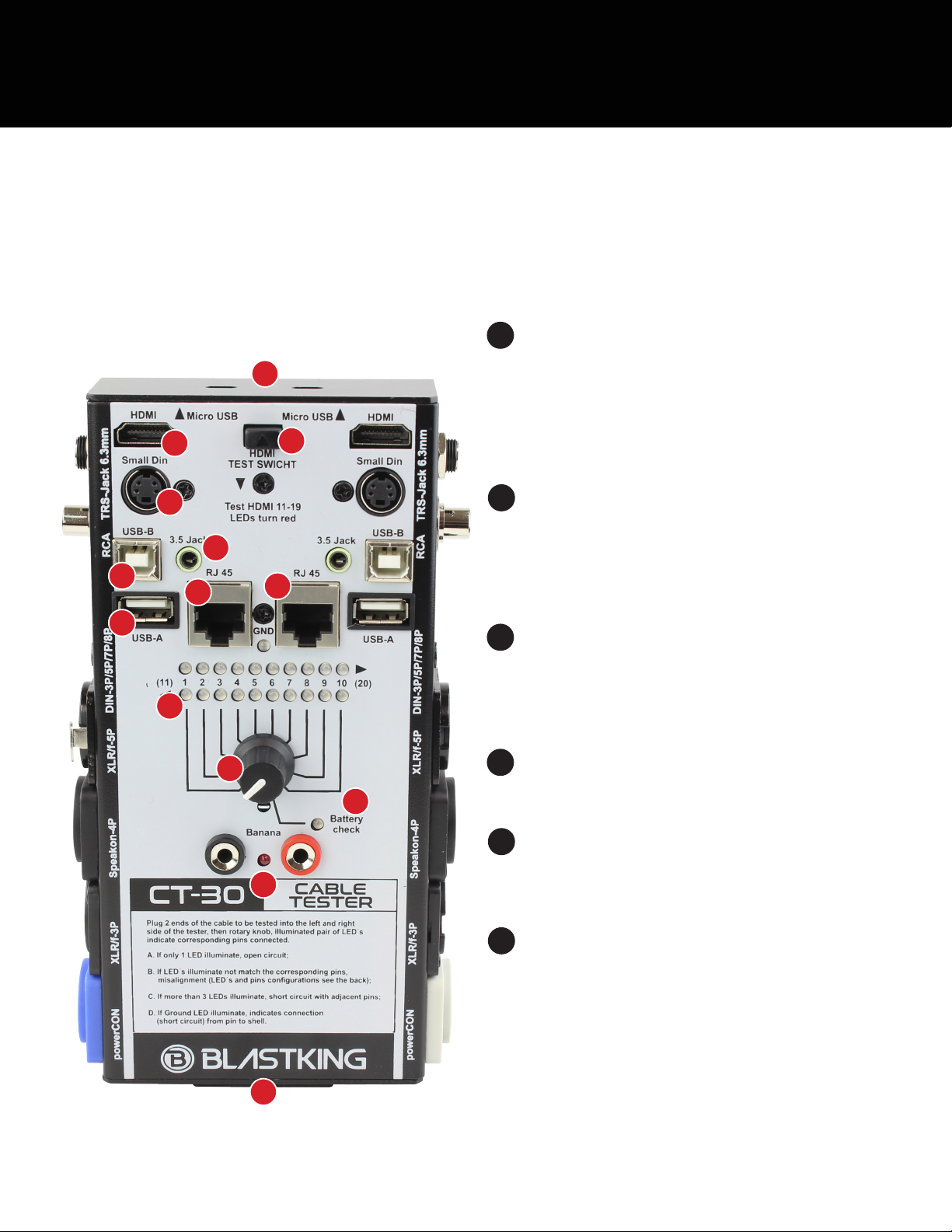
TOP AND SIDE PANEL FEATURES 19V Battery (not included)
411-Way Knob
3Battery Check LED
2Banana / Continuity
The battery cover is located on the front panel of the CT-30 and
easy to access. Simply lift up and out on the bottom tab of the
removable battery case cover; it will slide out competely.
Line up the positive (+) and negative (-) terminals of the battery with
the terminal listings printed on the bottom of the battery case cover.
The terminal cutouts of the battery case cover are cut to size for
convenience.
Attach the banana plug end of each probe (not included) to the
banana jack connector of the CT-30; they are color-coded for
convenience.
Use the probe end of the cables to test continuity between any two
points. When continuity occurs, the LED will illuminate yellow and a
high-pitched beep appears.
Rotate the 11-way knob [4] to the far-right (Battery Check) position.
The battery check LED will illuminate green to indicate the strength
of the battery. A brightly illuminated LED indicates a fully-charged
(or close to fully-charged) battery while a dimly lit LED indicates a
weaker battery that will need to be replaced soon.
This knob may be rotated to check the cable status of pin inputs
1–10, as well as the battery strength (far right).
5Ground LED
The ground LED will illuminate red to (1) indicate that the corre-
sponding contact and chassis are properly grounded or (2) indicate
that there is a short circuit from the pin to the shell.
GETTING STARTED
1. Insert 9V battery.
2. Connect one end of the cable to the proper input jack and the other end of the cable to the proper output jack.
3. Rotate the knob to verify cable / battery / ground status
1
2
6
4
3
75
6Pin Indicator LEDs
Plug two ends of the cable to be tested into the appropriate input on
the left and right side of the tester. Then rotate the knob accordingly.
A. An illuminated pair of LED’s indicates that corresponding pins are
successfully connected.
B. If only one LED is illuminated, please check the connection to
make sure both sides are properly inserted.
C. If three or more LED’s are illuminated, this is an indication of a
short circuit on adjacent pins.
D. If the red GND (Ground) LED is illuminated, the contact is
connecting to the connector shell causing a short.
13
12
11
10
9
8
14