www.blaubergventilatoren.de
3
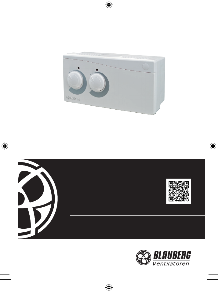
TE / TI / HSE / HSI / LSE / LSI/ IRSE / IRSI
EINLEITUNG
Die vorliegende Betriebsanleitung enthält
eine technische Beschreibung, technische
Daten, Funktions- und Wartungsvorschriften,
Sicherheitsvorschriften und Warnungen für einen
sicheren und störungsfreien Betrieb des Geräts.
Vor der Montage und Inbetriebnahme des
Geräts lesen Sie bitte die Betriebsanleitung
sorgfältig durch und achten Sie insbesondere auf
die Sicherheitsvorschriften. Bewahren Sie diese
Anleitung auf, solange Sie das Gerät verwenden.
ALLGEMEINE INFORMATIONEN
Der Timer / Sensor mit Timer ist für die
Automatisierung des Steuerungssystems für
Kleinraumventilatoren je nach Luftfeuchtigkeit,
Lichtstärke, Bewegungssensors oder Betätigung
eines externen Schalters im Raum bestimmt. Je
nach dem Modell ist das Gerät für Aufputz- oder
Unterputzmontage ausgelegt.
SICHERHEITSVORSCHRIFTEN
Trennen Sie das Gerät von der Stromversorgung
vor jegliche Arbeiten. Sämtliche Service- und
Wartungsarbeiten sind nach vorherigem Studium der
Betriebsanleitung vom Fachpersonal gestattet, das über
eine gültige Zulassung für elektrische Arbeiten verfügt.
Unsachgemäße Verwendung und unberechtigte
Änderungen am Gerät sind nicht gestattet. Erfüllen
Sie die vorliegenden Anforderungen, um eine lange
Lebensdauer des Geräts zu sichern.
LAGER UND BEFÖRDERUNGSVORSCHRIFTEN
Beförderung ist mit jeder Fahrzeugart in der
Originalverpackung des Herstellers erlaubt. Die
Verpackung muss gegen Witterungseinüsse sowie
mechanische Beschädigungen geschützt sein.
Das gelieferten Gerät in der Originalverpackung des
Herstellers kühl und trocken lagern.
Das Lagerumfeld darf keinen aggressiven und/
oder chemischen Dämpfen, Mischungen oder
Fremdstoen ausgesetzt sein, die Korrosion
verursachen und Anschluss-Abdichtungen
beschädigen können.
Das Gerät ist in einer Umgebung zu lagern, wo
das Risiko der mechanischen Beschädigungen,
Temperatur- und Feuchtigkeitsschwankungen
minimiert sind, bei einer Umgebungstemperatur
von +5°C bis + 40°C gelagert werden.
HERSTELLERGARANTIE
Das Gerät entspricht den Europäischen
Normen und Standarten, den Richtlinien über
die Niederspannung und elektromagnetische
Verträglichkeit.
Hiermit erklären wir, dass das Produkt
mit der maßgeblichen Anforderungen aus
Richtlinie 2004/108/EG über elektromagnetische
Verträglichkeit, Richtlinie 89/336/EWG, und
Niederspannungsrichtlinie 2006/95/EG, Richtlinie
73/23/EWG, und Richtlinie 93/68/EWG über CE-
Kennzeichnung übereinstimmt.
Der Hersteller garantiert einen normalen Betrieb
des Geräts für zwei Jahre ab dem Verkauf durch
das Einzelhandelsnetz unter der Voraussetzung,
dass die Beförderungs-, Lagerungs-, Montage- und
Betriebsregeln eingehalten wurden.
Im Falle einer Betriebsstörung während der
Garantiefrist welche auf einVerschulden des Herstellers
zurückzuführen ist, hat der Kunde den Anspruch auf
Reparatur oder ein Austauschgerät. Die Abwicklung
ndet über den Händler statt. Beim Fehlen eines
Kaufbelegs wird die Gewährleistungsfrist ab Moment
der Herstellung berechnet.
Der HERSTELLER haftet nicht für die
Beschädigungen, die in Folge von falscher
Anwendung des Geräts oder durch einen groben
mechanischen Eingri entstanden sind.
Der HERSTELLER haftet nicht für Schäden, die an
oder durch Geräte/n Dritter verursacht wurden.
WARNUNG
Nicht in den Restmüll! Das Gerät
enthält teils wiederverwendbare Stoffe,
teils Substanzen, die nicht in den Restmüll
gelangen dürfen. Entsorgen Sie das Gerät
nach Ablauf seiner Lebensdauer nach den in
Ihrem Land geltenden Bestimmungen.
WARNUNG
Das Gerät darf nicht von Kindern oder Personen mit einge-
schränkten körperlichen, sensorischen oder geistigen Fähigkeiten
betreiben werden. Das Gerät ist nicht für den Einsatz durch Per-
sonen, die keine genügende Erfahrung oder Sachwissen haben,
außer wenn sie unter Kontrolle stehen oder von einer für ihre
Sicherheit zuständigen Person angewiesen werden. Kinder müs-
sen beaufsichtigt werden und dürfen nicht an dem Gerät spielen.
T_HS_LS_IRS_v.2(3)_DE_EN_105x148.indd 3 22.09.2015 14:22:52