Blaze 600 D TURBO User manual

CAMPO EQUIPMENT CO. LTD. (ECOBLAZE)
6 Carson Court, Brampton, ON, CANADA, L6T 4P8
Tel: (905) 793-2525 | Fax: (905) 793-8768 | www.campoequipment.com Page | 1
OIL/NG/LP FIRED SPACE HEATER: BLAZE 600 D/G TURBO
REPORT # 0367MH007S
Installation Instructions-Manual-Maintenance-Parts List
CAUTION: DO NOT TAMPER WITH HEATER OR ITS CONTROLS. CALL A QUALIFIED SERVICE TECHNICIAN
Retain manual for future reference June 17, 2016
CERTIFIED FOR USE IN CANADA AND THE U.S.A.
CAMPO EQUIPMENT CO. LTD. (ECOBLAZE)
6 Carson Court, Brampton, ON, CANADA, L6T 4P8
Tel: (905) 793-2525 | Fax: (905) 793-8768 | www.campoequipment.com Page | 2

CAMPO EQUIPMENT CO. LTD. (ECOBLAZE)
6 Carson Court, Brampton, ON, CANADA, L6T 4P8
Tel: (905) 793-2525 | Fax: (905) 793-8768 | www.campoequipment.com Page | 3
READ INSTRUCTIONS PRIOR TO STARTING HEATERS
THIS HEATER IS DESIGNED AND APPROVED FOR USE AS A CONSTRUCTION HEATER
UNDER STANDARD ANSI Z83.7-2011/CSA2.14-2011, UL 733-2013 and CAN/CSA B140.8-
1967(R2015)
THESE HEATERS ARE SUITABLE FOR OUTDOOR USE
THE REQUIREMENTS OF LOCAL AUTHORITIES HAVING JURISDICTION SHALL BE
FOLLOWED
BLAZE 600 G TURBO
NOTE: THIS HEATER IS INTENDED FOR USE PRIMARILY AS TEMPORARY HEATING OF BUILDINGS UNDER
CONSTRUCTION, ALTERATION OR REPAIR
THIS UNIT IS APPROVED FOR USE WITH PROPANE OR NATURAL GAS. NEVER ATTEMPT TO BURN
GARBAGE OR PAPER IN THE HEATER AND REMOVE ALL PAPER AND RAGS FROM AROUND THE
HEATER. FOR YOUR SAFETY, DO NOT STORE OR USE GASOLINE OR OTHER FLAMMABLE
LIQUIDS OR VAPOURS IN THE VICINITY OF THE HEATER.
DO NOT TAMPER WITH THE HEATER AND CONTROLS! THE HEATER MUST BE SERVICED BY
QUALIFIED SERVICE PERSONNEL.
WARNING: THOSE WHO INSTALL THE HEATER MUST HAVE THE TRAINING AND EXPERIENCE
NECESSARY TO DO SO. READ THIS MANUAL CAREFULLY. FAILURE TO PROPERLY INSTALL
AND SETUP THE HEATER COULD RESULT IN PROPERTY DAMAGE, PERSONAL INJURY, OR LOSS
OF LIFE. THE QUALIFIED SERVICE PERSONNEL PERFORMING THIS WORK ASSUMES A SERIOUS
RESPONSIBILITY FOR THE CORRECT INSTALLATION, SETUP, AND START-UP OF THE HEATER.
THIS HEATER IS DESIGNED AND APPROVED FOR USE AS A CONSTRUCTION HEATER IN
ACCORDANCE WITH STANDARD ANSI Z83.7-2011/CSA2.14-2015. CHECK WITH YOUR
LOCAL FIRE SAFETY AUTHORITY IF YOU HAVE QUESTIONS ABOUT APPLICATIONS.
WARNING: INTENDED USE IS PRIMARILY THE TEMPORARY HEATING OF BUILDINGS UNDER
CONSTRUCTION, ALTERATION, REPAIR OR EMERGENCIES ONLY.
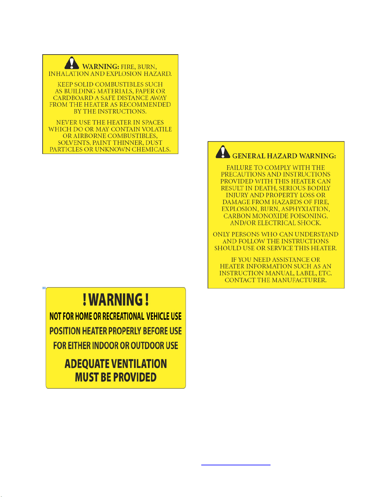
WARNING: ALWAYS PROVIDE ADEQUATE VENTILATION. MINIMUM ACCEPTABLE VENTILATION
REQUIRED: 1 SQ. IN. OF FRESH AIR MUST BE SUPPLIED FOR EVERY 1000 BTU/H OF HEAT.
WARNING: THIS HEATER SHALL BE INSTALLED SUCH THAT IT IS NOT DIRECTLY EXPOSED TO
WATER SPRAY, AND/OR DRIPPING WATER.
CHECK WITH YOUR LOCAL FIRE SAFETY AUTHORITY IF YOU HAVE QUESTIONS ABOUT
APPLICATIONS
THESE INSTRUCTIONS HAVE BEEN THOROUGHLY WRITTEN, BUT THEY CANNOT COVER EVERY
PECULIAR INSTALLATION AND CONTINGENCY. THEREFORE IF THERE IS ANY DOUBT AS TO

CAMPO EQUIPMENT CO. LTD. (ECOBLAZE)
6 Carson Court, Brampton, ON, CANADA, L6T 4P8
Tel: (905) 793-2525 | Fax: (905) 793-8768 | www.campoequipment.com Page | 4
INTERPRETATION OF ANY REQUIREMENTS, CONTACT YOUR LOCAL AUTHORITY HAVING
JURISDICTION, YOUR LOCAL DISTRIBUTOR, OR THE FACTORY.
INSTALLATION REGULATIONS:
1.) THE INSTALLATION OF THE UNIT SHALL BE IN ACCORDANCE WITH THE REGULATIONS OF
THE AUTHORITIES HAVING JURISDICTION.
WIRING: ALL INTERNAL WIRING OF THE HEATER IS COMPLETED BY THE MANUFACTURER. ALL
EXTERNAL WIRING MUST CONFORM TO EXISTING ELECTRICAL CODES AS LAID DOWN BY THE
AUTHORITIES HAVING JURISDICTION.
THE INSTALLATION OF THIS HEATER FOR USE WITH NATURAL GAS SHALL CONFORM WITH
LOCAL CODES OR, IN THE ABSENCE OF CODES, WITH THE NATIONAL FUEL GAS CODE ANSI
Z223.1/NFPA 54 AND THE NATURAL GAS AND PROPANE INSTALLATION CODE, CSA B149.1-00.
THIS HEATER MUST BE INSTALLED BY A QUALIFIED GAS TECHNICIAN, FOLLOWING LOCAL
CODES PUBLISHED BY THE AUTHORITY HAVING JURISDICTION. ALL INSTALLATIONS
PERFORMED IN THE STATE OF MASSACHUSETTS MUST BE COMPLETED BY A QUALIFIED
PLUMBER AND GAS FITTER OF THE STATE OF MASSACHUSETTS.
THE INSTALLATION OF THIS HEATER FOR USE WITH A PROPANE TANK OR CYLINDER SHALL
CONFORM WITH LOCAL CODES OR IN THE ABSENCE OF LOCAL CODES, WITH THE STANDARD
FOR THE STORAGE AND HANDLING OF LIQUEFIED PETROLEUM GASES, ANSI/NFPA 58 AND THE
NATURAL GAS AND PROPANE INSTALLATION CODE, CSA B149.1
THIS HEATER MUST BE LOCATED AT LEAST 10FT (3M) FROM ANY PROPANE GAS CYLINDER.
THIS HEATER SHALL NOT BE DIRECTED TOWARD ANY PROPANE GAS CONTAINER WITHIN 20FT
(6M).
OTHER STANDARDS GOVERN THE USE OF FUEL GASES AND HEAT PRODUCING
PRODUCTS IN SPECIFIC APPLICATIONS. YOUR LOCAL AUTHORITY CAN ADVISE YOU
ABOUT THESE.
READ INSTRUCTIONS PRIOR TO STARTING HEATERS
BLAZE 600 D TURBO
THIS UNIT IS APPROVED FOR USE WITH NO. 1 AND NO. 2 FUEL OIL. NEVER USE GASOLINE OR
CRANKCASE OIL WHICH MAY CONTAIN GASOLINE AS FUEL FOR THE HEATER. NEVER ATTEMPT
TO BURN GARBAGE OR PAPER IN THE HEATER AND REMOVE ALL PAPER AND RAGS FROM
AROUND THE HEATER. FOR YOUR SAFETY, DO NOT STORE OR USE GASOLINE OR OTHER
FLAMMABLE LIQUIDS OR VAPOURS IN THE VICINITY OF THE HEATER.
FOR YOUR SAFETY DO NOT ATTEMPT TO START THE HEATER IF:
1.) EXCESS OIL HAS ACCUMULATED
2.) THE HEATER IS FULL OF VAPOUR
3.) THE COMBUSTION CHAMBER IS EXTREMELY HOT

CAMPO EQUIPMENT CO. LTD. (ECOBLAZE)
6 Carson Court, Brampton, ON, CANADA, L6T 4P8
Tel: (905) 793-2525 | Fax: (905) 793-8768 | www.campoequipment.com Page | 5
DO NOT TAMPER WITH THE HEATER AND CONTROLS! THE HEATER MUST BE SERVICED BY
QUALIFIED SERVICE PERSONNEL.
WARNING: THOSE WHO INSTALL THE HEATER MUST HAVE THE TRAINING AND EXPERIENCE
NECESSARY TO DO SO. READ THIS MANUAL CAREFULLY. FAILURE TO PROPERLY INSTALL
AND SETUP THE HEATER COULD RESULT IN PROPERTY DAMAGE, PERSONAL INJURY, OR LOSS
OF LIFE. THE QUALIFIED SERVICE PERSONNEL PERFORMING THIS WORK ASSUMES A SERIOUS
RESPONSIBILITY FOR THE CORRECT INSTALLATION, SETUP, AND START-UP OF THE HEATER.
THESE INSTRUCTIONS HAVE BEEN THOROUGHLY WRITTEN, BUT THEY CANNOT COVER EVERY
PECULIAR INSTALLATION AND CONTINGENCY. THEREFORE IF THERE IS ANY DOUBT AS TO
INTERPRETATION OF ANY REQUIREMENTS, CONTACT YOUR LOCAL AUTHORITY HAVING
JURISDICTION, YOUR LOCAL DISTRIBUTOR, OR THE FACTORY.
IMPORTANT: IF YOU OBSERVE THE PRIMARY CONTROL IS LOCKED OUT, PUSH THE RED RESET
BUTTON ONLY ONCE. IF THE BURNER DOES NOT RE-LIGHT, DO NOT PUSH THE BUTTON A
SECOND TIME OR EXCESS OIL WILL ACCUMULATE IN THE COMBUSTION CHAMBER—CALL A
QUALIFIED SERVICE PERSON.
INSTALLATION REGULATIONS:
1.) INSTALLATION SHOULD BE IN ACCORDANCE WITH ALL LOCAL AND NATIONAL
REGULATIONS.
2.) IN CANADA USE THE CSA B139-1962 INSTALLATION CODE FOR OIL BURNING EQUIPMENT,
FOR RECOMMENDED INSTALLATION PRACTICE.
WIRING: ALL INTERNAL WIRING OF THE HEATER IS COMPLETED BY THE MANUFACTURER. ALL
EXTERNAL WIRING MUST CONFORM TO EXISTING ELECTRICAL CODES AS LAID DOWN BY THE
AUTHORITIES HAVING JURISDICTION. IN CANADA, REFER TO CSA C22.1 CANADIAN ELECTRICAL
CODE AND IN THE UNITED STATES AS OUTLINED IN THE BOCA CODE, OR THE NFPA 70 NATIONAL
ELECTRICAL CODE.
WARNING: LACK OF COMBUSTION AIR CAN CAUSE A DIRTY FIRE, ODOURS IN ENCLOSED
SPACES, AND BACKDRAFTING, POTENTIALLY RESULTING IN NAUSEA OR ASPHYXIATION OF
THE OCCUPANTS.
BLAZE 600 D/G
SPECIFICATIONS
BLAZE 600G-
BECKETT (NG/LP)
BLAZE 600D-
BECKETT (OIL)
Burner Make & Model CG10 CF800
Voltage 120V
120V
Input (BTU/h) 575,000 NO.1 (581,699) @ 175 PSI
NO.2 (588,000) @ 175 PSI
CFM/AMPS 5,500/11.5 5,500/11.5
MOTOR HP
1
1

CAMPO EQUIPMENT CO. LTD. (ECOBLAZE)
6 Carson Court, Brampton, ON, CANADA, L6T 4P8
Tel: (905) 793-2525 | Fax: (905) 793-8768 | www.campoequipment.com Page | 6
Ductability
(Return/Supply)
Static Pressure
24ft/150ft
upto 4”
24ft/150ft
upto4”
Outlet Duct Size
2 X 12" OR 1 X 16
2 X 12" OR 1 X 16
Inlet Duct Size
2 X 12" OR 1 X 16
2 X 12" OR 1 X 16
Gas Conversion Easy switch over
Blue handle Ball
Valve on Gas
manifold.
Closed position:
Propane
Open position:
Natural Gas
N/A
Manifold pressure “W.C.
2.9”NG or 2.9”LP
(Pressure to be set
before NG/LP
switchover valve
and after adjusting
valve on manifold-
1.7” if set after the
N/LP Switchover
valve)
N/A
Minimum/Maximum
Supply Pressure “W.C.
8/10
FOR NG AND LP
OPERATION
N/A
Nozzle
N/A
2.75 X 60b
Pump Pressure
N/A
175
GPH
N/A
4.2
Fuel
NG or LP
No. 1 or No. 2 /
Kerosene or Furnace
Oil
Head Setting
10.3 (10.1 head)
1
Air Setting (Beckett-
Shutter/Band)
10/0 3/0

CAMPO EQUIPMENT CO. LTD. (ECOBLAZE)
6 Carson Court, Brampton, ON, CANADA, L6T 4P8
Tel: (905) 793-2525 | Fax: (905) 793-8768 | www.campoequipment.com Page | 7
CONNECTING THE CYLINDER
Clearance to LP containers: 10 feet (3M)
IF CYLINDERS ARE USED TO SUPPLY THE HEATER, NO CYLINDERS SMALLER THAN 100
LB CAPACITY SHALL BE USED. THESE CYLINDERS MUST SUPPLY A VAPOUR
WITHDRAWAL ONLY.
1.) ALL CYLINDER CONNECTIONS MUST BE MADE USING A WRENCH TO TIGHTEN THE
POL FITTING.
2.) BE SURE THAT THE CYLINDER VALVE IS IN THE CLOSED POSITION WHEN
CONNECTING OR DISCONNECTING THE CYLINDER.
3.) PROPER PROCEDURE FOR GAS LEAK TESTING: A SOAP AND WATER SOLUTION
MUST BE APPLIED TO ALL CONNECTIONS IN ORDER TO LEAK CHECK THE SYSTEM.
4.) THE HOSE ASSEMBLY MUST BE VISUALLY INSPECTED PRIOR TO EACH USE OF
THE HEATER.
THE GAS MUST BE TURNED OFF AT THE PROPANE SUPPLY CYLINDER(S) WHEN THE
HEATER IS NOT IN USE. WHEN THE HEATER IS TO BE STORED INDOORS, THE
CONNECTION BETWEEN THE PROPANE SUPPLY CYLINDER(S) AND THE HEATER MUST
BE DISCONNECTED AND THE CYLINDERS REMOVED FROM THE HEATER AND STORED IN
ACCORDANCE WITH STANDARDS FOR THE STORAGE AND HANDLING OF LIQUIFIED
PETROLEUM GASES, ANSI/NFPA 58 AND CSA B149.1, NATURAL GAS AND PROPANE
INSTALLATION CODE.
PIPING: THIS HEATER MUST BE INSTALLED BY A QUALIFIED GAS TECHNICIAN
FOLLOWING LOCAL CODES PUBLISHED BY THE AUTHORITY HAVING JURISDICTION.
SIZING OF SUPPLY PIPING MUST BE DETERMINED USING THE LENGTH OF PIPE RUN AS
WELL AS TOTAL BTUH RATING OF THE APPLIANCE(S). APPROPRIATE PIPING TABLES
MUST BE USED TO DETERMINE SIZE OF SUPPLY PIPING DEPENDANT ON THE LENGTH
OF RUN FROM SOURCE.
CONNECTING TO AN EXTERNAL FUEL TANK
(BLAZE 600 D TURBO)
APPROVAL AGENCY OMNI OMNI
DRY WEIGHT (lbs.) 600 600
Dimensions 76.7” x 31” x 58”
76.7” x 31” x 58”
FLUE SIZE
6”
6”

CAMPO EQUIPMENT CO. LTD. (ECOBLAZE)
6 Carson Court, Brampton, ON, CANADA, L6T 4P8
Tel: (905) 793-2525 | Fax: (905) 793-8768 | www.campoequipment.com Page | 8
Beckett CF800 is fitted with 3/8” SAE male fittings and is set up for a 2 line system to eliminate
priming. Ensure fuel tank has a supply line and a return line and connect the supply line to the 3/8”
SAE fitting on the inlet side of the fuel filter and the return line to the return fitting located on the
Beckett Burner pump. For a 1 line system remove bypass plug located on inlet port of Beckett
Pump and just connect fuel line to inlet side of fuel filter.
FUEL (BLAZE 600 G TURBO)
THIS HEATER WILL OPERATE ON PROPANE OR NATURAL GAS—NOT BOTH. THE
MANIFOLD PRESSURES ARE LISTED ON THE APPROVAL LABEL. TO DETERMINE WHICH
FUEL TO USE SEE RATING PLATE. DO NOT ATTEMPT TO USE THE HEATER WITHOUT
CONSULTING THE RATING PLATE.
NOTE: THE PROPER POSITION ON THE EASY SWITCH OVER BLUE HANDLE BALL VALVE
MUST BE USED AND RATING PLATE MUST REFLECT THE FUEL THE HEATER IS BURNING.
DO NOT OPERATE THE HEATER WITHOUT CONSULTING THE RATING PLATE.
HEATER CONVERSION MUST BE DONE BY A QUALIFIED TECHNICIAN AND RATING PLATE
MUST REFLECT ANY CHANGE.
THIS UNIT HEATER IS EQUIPPED FOR NATURAL GAS OR LP GAS. THIS UNIT HEATER IS
EQUIPPED WITH ORIFICES SIZED FOR OPERATION WITH NATURAL OR LP GAS VIA THE
EASY SWITCH OVER BLUE HANDLE BALL VALVE. FOR CONVERSION TO LP (OR
NATURAL) GAS SEE INSTRUCTION PLATE ON THE APPLIANCE.
EasyswitchoverBluehandleBallValveonGasmanifold.
Closedposition:Propane
Openposition:NaturalGas
HOSES
ALL HOSES USED TO CONNECT THIS HEATER TO FUEL SUPPLY MUST BE TYPE 1
APPROVED PROPANE/NATURAL GAS HOSE ASSEMBLIES.
ELECTRICAL
WARNING: ELECTRICAL GROUNDING INSTRUCTIONS
THIS APPLIANCE IS ABLE IS TO RECEIVE 1 PHASE POWER.
120V SUPPLY MUST BE AVAILABLE.
INSTALLATION

CAMPO EQUIPMENT CO. LTD. (ECOBLAZE)
6 Carson Court, Brampton, ON, CANADA, L6T 4P8
Tel: (905) 793-2525 | Fax: (905) 793-8768 | www.campoequipment.com Page | 9
12/3 AWG UPTO 50FT
10/3 AWG BEYOND 50FT
NOTE: IF ANY OF THE ORIGINAL WIRE AS SUPPLIED WITH THE APPLIANCE MUST BE
REPLACED, IT MUST BE REPLACED WITH TYPE TEW 14GA WIRE OR ITS EQUIVALENT.
ELECTRICAL SYSTEM BLAZE
600 D/G
Volts-Hertz-Phase 120-60-1
Full Load (Amps) 11.5
Max fuse size in AMPS
with time delay
15
The electrical grounding of the heater shall be in compliance with the National Electrical Code, ANSI/NFPA
70, or the CSA C22.1, Canadian Electrical Code, Part I
CAMPO EQUIPMENT CO. LTD. (ECOBLAZE)
6 Carson Court, Brampton, ON, CANADA, L6T 4P8
Tel: (905) 793-2525 | Fax: (905) 793-8768 | www.campoequipment.com Page | 10
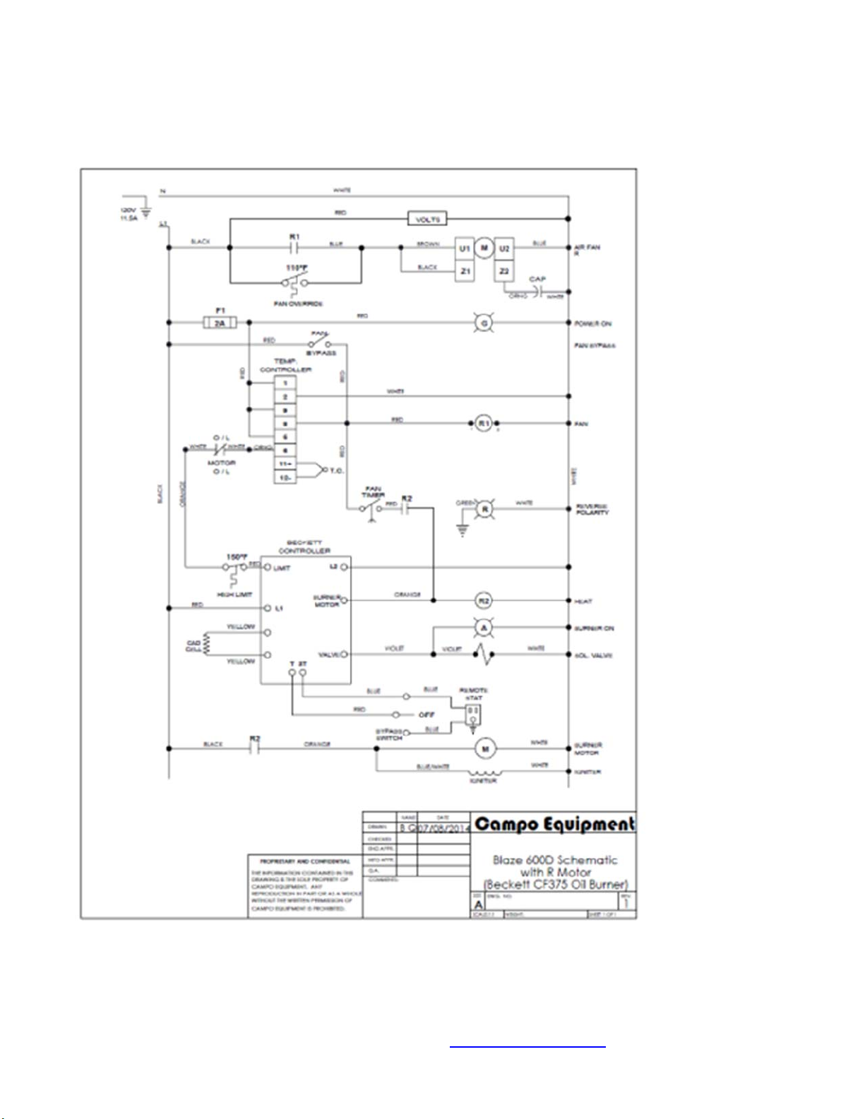
Blaze 600D Turbo Schematic with R Motor
(Beckett CF800 Oil Burner)

CAMPO EQUIPMENT CO. LTD. (ECOBLAZE)
6 Carson Court, Brampton, ON, CANADA, L6T 4P8
Tel: (905) 793-2525 | Fax: (905) 793-8768 | www.campoequipment.com Page | 11
Blaze 600G Turbo Schematic with R Fan-Beckett CG10

CAMPO EQUIPMENT CO. LTD. (ECOBLAZE)
6 Carson Court, Brampton, ON, CANADA, L6T 4P8
Tel: (905) 793-2525 | Fax: (905) 793-8768 | www.campoequipment.com Page | 12
SEQUENCE OF OPERATION FOR BLAZE 600 D/G TURBO
With “Selector Switch” in “ON” position and selector switch in “STAT ON” position and remote
thermostat plugged into receptacle:
1: Remote Thermostat senses a drop in temperature and the ignition control module is energized.
2: The module performs a safe start check and the burner and spark generator start. Burner lights, ignition
stops, and flame current is sensed.
For oil: the Genisys primary control contacts close, the burner motor and ignitor are
energized after a 15 second delay. The primary control energizes the pump solenoid valve and flame is
established. The cad cell senses flame and the burner continues to fire.
3: Temperature controller thermocouple heats up to factory set point (90F) OR after Time Delay of 1
minute and circulating air blower starts.
4: When the remote thermostat senses space temperature at set point, the burner shuts down.
5: The circulating blower continues to operate until the air in the unit cools to the factory set point (80 ºF)
then turns off.
With selector switch in “BYPASS” position:
1: The module performs a safe start check and the burner and spark generator start.
2: Burner lights, ignition stops, and flame current is sensed.
3: Temperature controller thermocouple heats up to factory set point (90F) and circulating air blower starts.
4: When the selector switch is placed to the off position the burner shuts down.
5: The circulating blower continues to operate until the air in the unit cools to the factory set point (80F)
then turns off.
OPERATING INSTRUCTIONS FOR BLAZE 600 D/G TURBO
STARTING HEATER
1.) ENSURE HEATER IS ON FLAT, LEVEL GROUND BEFORE STARTING, CANOPY AND FAN GUARDS
MUST BE CLOSED.
2.) MAKE SURE “SELECTOR SWITCH” IS IN “OFF” POSITION.
3.) WIRE IN SUPPLY CORD TO 120V SUPPLY WITH GROUND.
INSTALLATION
12/3 AWG UPTO 50FT
10/3 AWG BEYOND 50FT
4.) TURN “SELECTOR SWITCH” TO “ON” POSITION.
5.) FOR THERMOSTAT OPERATION FLIP SELECTOR SWITCH TO “STAT ON” POSITION. IF YOU ARE NOT
USING A THERMOSTAT FLIP SELECTOR SWITCH TO “BYPASS” POSITION.
Please Note: When using a generator for electrical supply, make sure the generator is properly grounded and
is running at a 60HZ frequency. In the event that a generator is being used and the generator runs out of fuel,
make sure the heater “SELECTOR SWITCH” is in the “OFF” position before restarting generator, failure to do
so may damage heater.
STOPPING HEATER
1.) Close main gas supply valve while heater is operating or if operating heater with oil skip to # 2.)
2.) Flip “SELECTOR SWITCH” to “OFF” position. The supply fan will continue to operate until the heat exchanger
has sufficiently cooled. Do not disconnect main power until supply fan has stopped running and “SELECTOR
SWITCH” is on “OFF” position.
3.) Disconnect heater from gas supply OR disconnect fuel oil lines.

CAMPO EQUIPMENT CO. LTD. (ECOBLAZE)
6 Carson Court, Brampton, ON, CANADA, L6T 4P8
Tel: (905) 793-2525 | Fax: (905) 793-8768 | www.campoequipment.com Page | 13
WARNING BEFORE REMOVING ANY GUARDS OR SAFETIES TURN “SELECTOR SWITCH” TO “OFF”
POSITION AND DISCONNECT THE MAIN POWER AS THE SUPPLY FAN WILL CYCLE AUTOMATICALLY.
IF HEATER FAILS TO START
1.) FOR BECKETT BURNERS 7575 or 7590 PRESS AND HOLD THE RED BUTTON ON THE BECKETT
CONTROLLER LOCATED ON THE CONTROL PANEL FOR 3 SECONDS TO RESET. FOR 7590 PRESS
RED BUTTON TO RESET.
2.) FOR GAS OPERATION CHECK GAS PRESSURE SUPPLY. SUPPLY AND MANIFOLD PRESSURE MUST
FOLLOW THOSE ON RATING PLATE. FOR OIL OPERATION CHECK FUEL LEVEL, FILTER, NOZZLE
AND SUCTION TUBING.
3.) ENSURE PROPER POWER SUPPLY AND WIRE GAUGE IS BEING USED.
4.) IF HEATER FAILS TO IGNITE AFTER 3 ATTEMPTS, CALL YOUR SUPPLIER FOR SERVICE.
NOTE: IF UNIT HAS BEEN RESET A NUMBER OF TIMES WITHOUT IGNITION -- DO NOT ATTEMPT TO START
THE HEATER: CONTACT A QUALIFIED SERVICE TECHNICIAN.
NOTE: IN OIL OPERATION IF UNIT HAS BEEN RESET A NUMBER OF TIMES WITHOUT IGNITION THERE WILL
BE AN ACCUMULATION OF OIL IN THE COMBUSTION CHAMBER! DO NOT ATTEMPT TO START THE
HEATER: CONTACT A QUALIFIED SERVICE TECHNICIAN.
CAUTION
1.) DO NOT SHUT OFF BY DISCONNECTING SUPPLY CORD. THE HEAT EXCHANGER SHOULD BE
PROPERLY COOLED BEFORE POWER SHUTDOWN.
2.) ALWAYS MAINTAIN ADEQUATE FUEL SUPPLY.
3.) IF GAS BURNER IS INSTALLED HEATER IS FOR USE WITH PROPANE OR NATURAL GAS ONLY.
SEE APPROVAL LABEL.
4.) DO NOT PLUG ANYTHING OTHER THAN THE THERMOSTAT INTO THE “REMOTE STAT” PLUG.
5.) FOLLOW ELECTRICAL REQUIREMENTS SHOWN ON RATING PLATE AND/OR ELECTRICAL
REQUIREMENTS SECTION OF THIS MANUAL.
6.) IN OIL OPERATION DO NOT START THE HEATER WHEN EXCESS OIL HAS ACCUMULATED IN
CHAMBER.
7.) IN OIL OPERATION DO NOT FILL TANK WHILE UNIT IS OPERATING.
8.) IN NO CASE SHOULD POWER CABLES BE SMALLER THAN WHAT IS STIPULATED ON
NAMEPLATE AND INSTRUCTION MANUAL.
9.) IN OIL OPERATION DO NOT USE GASOLINE, CRANKCASE OIL OR HEAVIER THAN NO. 2 FURNACE
OIL.
10.) DO NOT START THE HEATER WHEN THE CHAMBER IS HOT
11.) DO NOT FILL THE TANK WHILE THE UNIT IS OPERATING
12.) DO NOT TAMPER WITH THE UNIT. HAVE A COMPETENT SERVICE-TECHNICIAN MAKE ANY
ADJUSTMENTS
13.) MAX OUTLET TEMPERATURE (U.S./CA) 280F
14.) AT INSTALLATION ELEVATIONS ABOVE 2000 FT (610m), THE APPLIANCE SHALL BE DERATED 4
PERCENT FOR EACH 1000 FT (305m) OF ELEVATION ABOVE SEE LEVEL
15.) SHOULD OVERHEATING OCCUR, OR THE GAS SUPPLY CONTROL SYSTEM FAIL TO SHUT OFF
THE FLOW OF GAS, SHUT OFF THE MANUAL GAS VALVE TO THE UTILITY HEATER BEFORE
SHUTTING OFF THE ELECTRICAL SUPPLY.
16.) DO NOT USE THIS UTILITY HEATER IF ANY PART HAS BEEN UNDER WATER. IMMEDIATELY CALL
A QUALIFIED SERVICE TECHNICIAN TO INSPECT THE HEATER AND REPLACE ANY GAS
CONTROL WHICH HAS BEEN UNDER WATER.
ELECTRICAL REQUIREMENTS: 15 AMPS (1PH)

CAMPO EQUIPMENT CO. LTD. (ECOBLAZE)
6 Carson Court, Brampton, ON, CANADA, L6T 4P8
Tel: (905) 793-2525 | Fax: (905) 793-8768 | www.campoequipment.com Page | 14
INSTALLATION INSTRUCTIONS
1.) The recommendations of local authorities having jurisdiction must be followed. For
recommended installation practices refer to C.S.A. standard B139. (CANADA)
2.) When firing the unit in an enclosed area allow 1 square inch per thousand BTU’s (refer to
C.S.A. B139) to allow the free entry of the air required for operation.
3.) For electrical supply: 120V
INSTALLATION
12/3 AWG UPTO 50FT
10/3 AWG BEYOND 50FT
Do not operate the unit in partly ventilated areas without a flue pipe or in close proximity to
combustible surfaces or materials. Non Combustible floor must extend 6 feet on all sides of
the unit.
NOTE: Installation clearances are as follows:
TOP 3 feet
SIDES 3 feet
BURNER END 3 feet
DISCHARGE END 10 feet
VENT CONNECTOR 3 feet
COMBUSTIBLE FLOOR 6 feet
FLUE PIPE CONNECTIONS
VENT TO OUTDOORS
FOR INSTALLATION ON NON-COMBUSTIBLE FLOORS ONLY
When the heater is connected to a flue pipe the flue pipe shall terminate in a vertical section at
least two feet long. Horizontal runs should have rise ratio of 1 in 10 away from the heater. Where
down drafts are liable to occur a vent cap should be used. All venting should correspond with the
CSA B139 standard or local codes.
CAUTION: HEATER FLUE TEMPERATURES CAN REACH 700 °F TO 900 °F THEREFORE IT IS
A RANGE THAT IS BOTH HAZARDOUS TO HUMANS AND HIGHER THAN THE AUTO-
IGNITION TEMPERATURES OF MANY MATERIALS. THEREFORE EXERCISE CAUTION IN
HEATER PLACEMENT AND THE USE OF AN INSULATED GUARD AND STACK IS HIGHLY
RECOMMENDED.
Horizontal venting runs shall always terminate with a minimum 24” vertical.
NOTE: FOR OPTIMAL COMBUSTION PERFORMANCE A 30” C-VENT FLUE EXTENSION WITH
RAIN CAP IS RECOMMENDED AT ALL TIMES.
Recommended chimney draft - .05 inches of water column

CAMPO EQUIPMENT CO. LTD. (ECOBLAZE)
6 Carson Court, Brampton, ON, CANADA, L6T 4P8
Tel: (905) 793-2525 | Fax: (905) 793-8768 | www.campoequipment.com Page | 15
INSTALLATION
CLEARANCES
MAXIMUM ALLOWABLE DUCT LENGTHS BLAZE 600 D/G TURBO I
RETURN DUCTS upto 24’
SUPPLY DUCTS upto 150’
THIS HEATER IS FOR USE WITH AND WITHOUT DUCTWORK
WHEN USING DUCTWORK AVOID ANY KINKS OR SHARP BENDS.
INSUFFICIENT INLET AIR OR INSUFFICIENT DISCHARGE AIR WILL CAUSE
THE HEATER TO OVERHEAT.
BLAZE 600 D/G TURBO MAINTENANCE INSTRUCTIONS
WARNING
EVERY CONSTRUCTION HEATER SHOULD BE INSPECTED
BEFORE EACH USE, AND AT LEAST ANNUALLY BY A QUALIFIED SERVICE
PERSON. INCORRECT MAINTENANCE MAY RESULT IN IMPROPER
OPERATION OF THE HEATER AND SERIOUS INJURY COULD OCCUR.
HOSE ASSEMBLIES
The hose assemblies shall be visually inspected prior to each use of the heater. If it is evident there is excessive
abrasion or wear, or the hose is cut, it must be replaced prior to the heater being put into operation. The replacement
hose assembly shall be that specified by the manufacturer.

CAMPO EQUIPMENT CO. LTD. (ECOBLAZE)
6 Carson Court, Brampton, ON, CANADA, L6T 4P8
Tel: (905) 793-2525 | Fax: (905) 793-8768 | www.campoequipment.com Page | 16
TEMPERATURE CONTROLLER AND THERMOCOUPLE
The temperature controller protocols should be checked every heating season to ensure the burner will shutdown if
temperature exceeds 280F at the outlet duct. This can be accomplished by restricting the air flow through the unit.
After tests are complete, remove restrictors as both inlet and outlet ducts must be open for proper operation.
The temperature controller setting of 90F and time delay of 1 minute has been selected to allow for preheating of the
heat exchanger to ensure that only heated air is allowed to enter the space. Upon satisfying the need for heat, the
temperature controller will continue to run the supply fan until the heat exchanger has cooled sufficiently. This feature
will help prolong the life of the heat exchanger. The temperature controller must be replaced if the fan motor does not
shut off after the heat exchanger has cooled down.
Temperature Controller Protocols
Fan Turns on at 90 F OR time delay of 1 minute
Out # 2 is set at 275º (This will cycle the burner off 280º and back on at 275º.) If the burner reset light goes on; you
need to go to the control panel. For the Beckett CG10A and CF800 the controller must be reset by pressing the reset
button.
There is a redundant 150F high limit switch.
During cool down the unit cools to 80F and then shuts down.
ELECTRICAL
Ensure all conduit (BX) connectors are tight. Open control panel door and burner compartment and check connections
are tight and no frayed wires exposed.
FAN
Check for dust or dirt build up on blades. Run heater to check for fan vibration. Replace fan blade if vibration is
noticeable. The flow of combustion and ventilation air must not be obstructed. Be sure to check the fan assembly and
ensure that the motor and blade are operating properly.
MOTOR
No lubrication is necessary since the bearings are the sealed type. Clean motor of existing dust or dirt.
GAS TRAIN (annual basis)
Connect gas supply to gas train with gas safety shut-off valves closed. Spray all of gas train components including
safety shut-off valves with soap and water solution to check for leaks. Open safety shut off valves on gas train and
spray with soap and water solution to check for leaks.
HEAT EXCHANGER
If a smoky condition continues even after adjusting the air assembly, the heat exchanger should be thoroughly
cleaned.
FUEL FILTER (OIL OPERATION)
Replace cartridge every six months of normal usage.
NOTE: FLOW OF COMBUSTION AND VENTILATION AIR CANNOT BE OBSTRUCTED
FLAME DETECTOR (OIL OPERATION)
When doing maintenance, turn on machine and run. After having machine run for a few minutes, press red button on
primary control. Hold for one second and then release. If light flashes once or twice or three times, cad cell is
functioning properly. If flashes four times, check alignment and proper flame. If correct a cleaning of the face of the

CAMPO EQUIPMENT CO. LTD. (ECOBLAZE)
6 Carson Court, Brampton, ON, CANADA, L6T 4P8
Tel: (905) 793-2525 | Fax: (905) 793-8768 | www.campoequipment.com Page | 17
cad cell with a soft non-abrasive cloth is recommended. If light flashes 4 times, follow above steps. If flashing four
times persists, replace cad cell.
LED FLASHES CAD CELL RESISTANCE
1 0-400 Ohms
2 400-800 Ohms
3 800-1600 Ohms
4 >=1600 Ohms
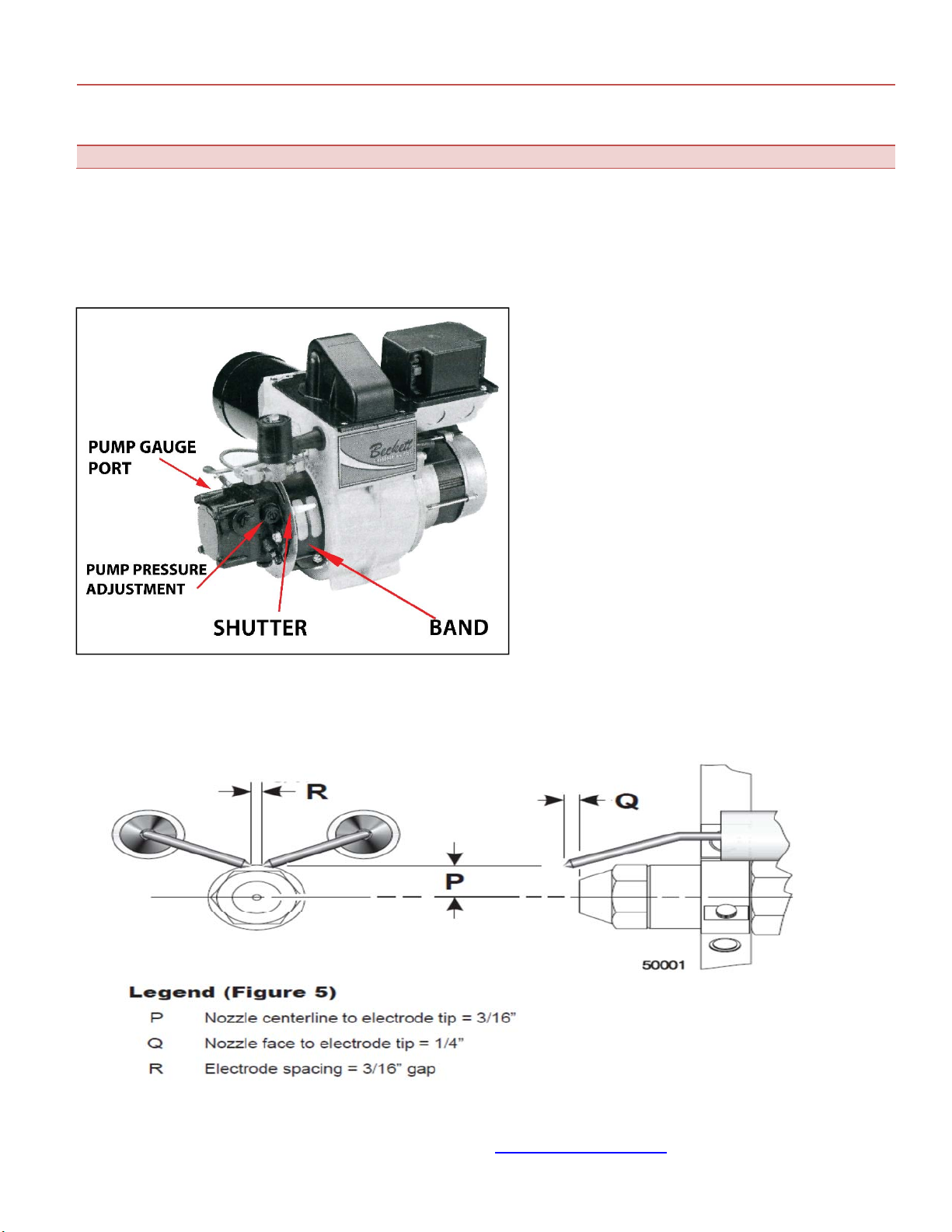
BURNER (OIL OPERATION)
The electrode spacing must be checked and adjusted, if necessary after every nozzle change. Nozzle should be
replaced annually or sooner if burner cannot be set up to operate properly. Nozzle size and type are marked on the
rating plate.
AFTER INSPECTION, A COMPLETE COMBUSTION TEST MUST BE PEFORMED AFTER EACH ANNUAL
SERVICE OF THE UNIT TO MAINTAIN OPTIMUM PERFORMANCE AND RELIABILITY.
WARNING: TURN OFF THE FUEL SUPPLIES AND POWER BEFORE PERFORMING
SERVICE WORK. THE 120V CIRCUIT IS A POTENTIAL ELECTROCUTION HAZARD.
COMBUSTION AIR ADJUSTMENTS
BLAZE 600 D/G
SPECIFICATIONS
BLAZE 600G-
BECKETT (NG/LP)
BLAZE 600D-
BECKETT (OIL)
Gas Conversion
Easy switch over
Blue handle Ball
Valve on Gas
manifold.
Closed position:
Propane
Open position:
Natural Gas
N/A
Manifold pressure “W.C.
2.9”NG or 2.9”LP
(Pressure to be set
before NG/LP
switchover valve
and after adjusting
valve on manifold-
1.7” if set after the
N/A

CAMPO EQUIPMENT CO. LTD. (ECOBLAZE)
6 Carson Court, Brampton, ON, CANADA, L6T 4P8
Tel: (905) 793-2525 | Fax: (905) 793-8768 | www.campoequipment.com Page | 18
N/LP Switchover
valve)
Minimum/Maximum
Supply Pressure “W.C.
8/10
FOR NG AND LP
OPERATION
N/A
Nozzle
N/A
2.75 X 60B
Pump Pressure
N/A
175
Head Setting
10.1
1
Air Setting (Beckett-
Shutter/Band)
10/3
3/0
NOTE: The above settings are approximations based upon clean equipment in proper working order. Combustion air
adjustments will vary with location, altitude and type of fuel used.
BECKETT CG10 (THE BECKETT CG10 BURNER IS DESIGNED TO BE USED SOLELY WITH THE BECKETT
7590 GAS BURNER PRIMARY CONTROL AND THE 7474 GAS IGNITER.
1.) Loosen shutter and band and move to desired settings.
2.) Once desired settings are attained lock in place by tightening back shutter and band screws.
CAMPO EQUIPMENT CO. LTD. (ECOBLAZE)
6 Carson Court, Brampton, ON, CANADA, L6T 4P8
Tel: (905) 793-2525 | Fax: (905) 793-8768 | www.campoequipment.com Page | 19
WARNING: LACK OF COMBUSTION AIR CAN CAUSE A DIRTY FIRE, ODOURS IN ENCLOSED
SPACES, AND BACKDRAFTING, POTENTIALLY RESULTING IN NAUSEA OR ASPHYXIATION OF
THE OCCUPANTS.
ALL AIR ADJUSTMENTS MUST BE DONE BY A QUALIFIED SERVICE TECHNICIAN
BECKETT CF800 OIL BURNER
COMBUSTION AIR ADJUSTMENTS
For proper combustion air adjustment a calibrated
gas analyzer and smoke tester should be used to
ensure complete combustion. Air adjustment should
be made at the correct input and be adjusted to
achieve 5% Oxygen and 12% CO2. For optimum
combustion efficiency the combustion air control
should be set to provide no more than No. 1 smoke
(Bacharach Scale). The Beckett burner has a
calibrated air band, which will assist in adjusting the
primary air for a good oil/air mixture. Adjust the air
band supply by loosening lock screws and moving air
shutter and if necessary the bulk air band. Begin by
reducing the air until the unit begins to produce
smoke. Increase air until no smoke is produced.
Check for excessive heat build up in the heat
exchanger. Insufficient air will cause flame
impingement and reduced heat exchanger life.
Increase air until heat build up has been eliminated.
Check for proper ignition. Once satisfied re-tighten all
screws and locking mechanisms.
This adjustment is to be carried out while the unit is operating and after 5 minutes of firing. Rotating the air bands on
the burner housing makes the adjustment.

CAMPO EQUIPMENT CO. LTD. (ECOBLAZE)
6 Carson Court, Brampton, ON, CANADA, L6T 4P8
Tel: (905) 793-2525 | Fax: (905) 793-8768 | www.campoequipment.com Page | 20
SETTING GAS FIRING RATES
1.) Choose BTU required and fuel supplied. For example 575,000 BTU and Natural Gas with the Beckett CG10.
2.) Adjust the manifold pressure to the recommended setting (6.2).
3.) Check nameplate for recommended air setting. A 10/3 air setting is recommended.
4.) Measure the carbon monoxide level and adjust air settings, if necessary, to regulate it to about 50 PPM for a
starting point.
5.) Measure the O2 or CO2 at the 50 PPM level. For example, assume the O2 is 1.5% (11% CO2).
6.) Open the air adjustment until the O2 level is increased to 3% O2. This should reduce the CO level and provide a
margin of reserve air to accommodate variable conditions.
7.) Sample the CO level again. It should be in the 0 to 50 PPM range—50 according to settings.
8.) Check the draft to ensure it still meets specifications. If a major change in draft is required, repeat the above
steps.
9.) Perform any final adjustments and lock the air settings securely. Run the burner through several cycles to verify
prompt ignition and stable burner operation.
SETTING OIL FIRING RATES
1.) Choose BTU required. For example 588,000 BTU..
2.) Check name plate for recommended pump pressure. 175 psi is recommended.
3.) Check nameplate for recommended air setting. A 3/0 air setting is recommended.
4.) Install a pressure gauge in pump gauge port and start the burner. Operate for 5 minutes until blower fan starts.
5.) Adjust pump pressure to 175 PSI.
6.) Adjust air band to 0 and adjust air shutter to 3.
7.) Check smoke and CO2 levels. Once attained, lock air band and shutter in place.
8.) Shut off burner, let unit cool down. The unit is now adjusted for 588,000 input BTU’s.
THERMOSTAT OPERATION
The BLAZE 600 D/G TURBO II can be operated with a thermostat control.
An optional remote thermostat is available for temperature control for the space being heated. To connect the
heatstat, simply plug the heatstat into an extension cord and the extension cord into the outlet marked “REMOTE
STAT”. Make sure selector is in the “STAT ON” position. Place the remote thermostat into the space that is being
heated. The unit will now shut down at the remote thermostat temperature setting.
BECKETT CG10 PARTS BREAKDOWN
This manual suits for next models
2
Table of contents
Languages:
Other Blaze Heater manuals


Popular Heater manuals by other brands


CONVECTAIR
CONVECTAIR DIVA 7647 Installation & operation instructions

HSS Hire
HSS Hire 56282 Operating & safety guide

Rowenta
Rowenta SO2330 user guide

STIEBEL ELTRON
STIEBEL ELTRON ETW 120 Operation and installation

Frico
Frico Elztrip EZ200 Mounting and operating instructions

Prem-I-Air
Prem-I-Air HQH2000H user guide