BLEMO ER51 Owner's manual
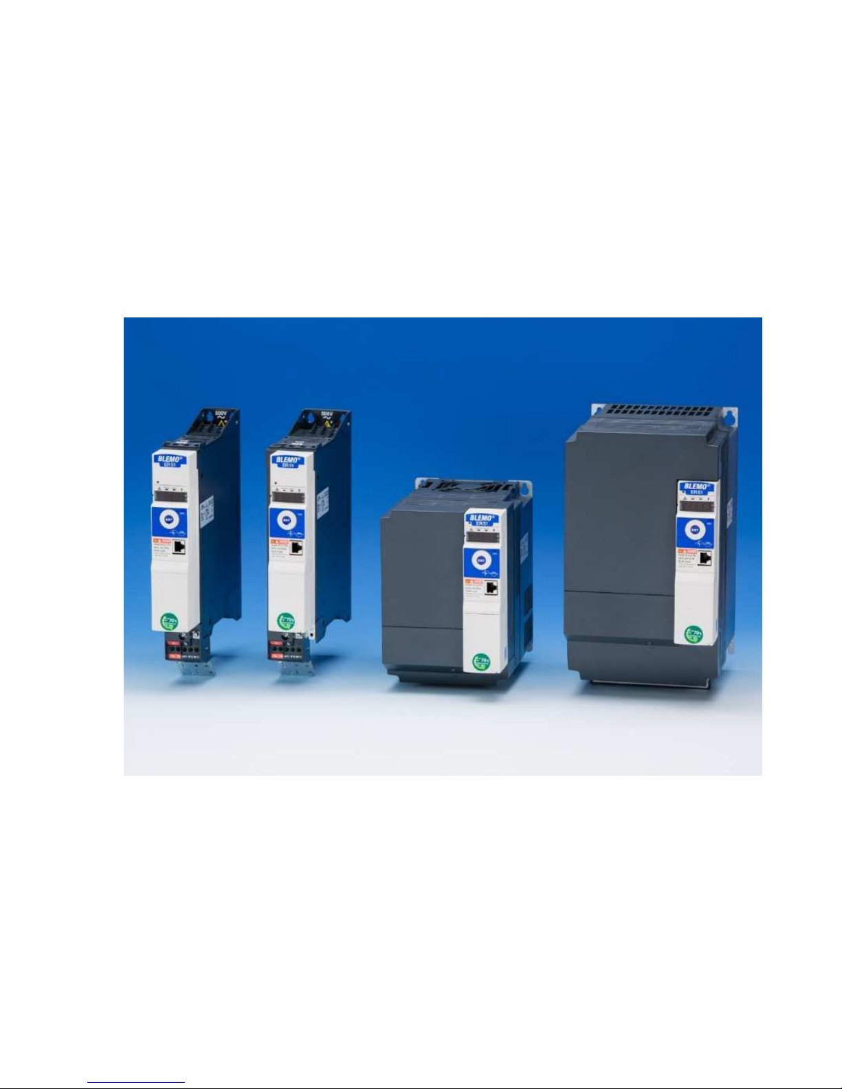
ER51
Variable speed drives for synchronous and
asynchronous motors
Programming Manual
02/2016
BLEMO
Frequenzumrichter
Siemensstraße 4
D-63110 Rodgau – Dudenhofen
Tel.: +49 / 6106 / 82 95-0
Fax: +49 / 6106 / 82 95-20
Web: www.blemo.com

2
S1A28692 03/2010
The information provided in this documentation contains general descriptions and/or technical characteristics of the performance
of the products contained herein. This documentation is not intended as a substitute for and is not to be used for determining
suitability or reliability of these products for specific user applications. It is the duty of any such user or integrator to perform the
appropriate and complete risk analysis, evaluation and testing of the products with respect to the relevant specific application or
use thereof. Neither BLEMO
®
nor any of its affiliates or subsidiaries shall be responsible or liable for misuse of the information
contained herein. If you have any suggestions for improvements or amendments or have found errors in this publication, please
notify us.
No part of this document may be reproduced in any form or by any means, electronic or mechanical, including photocopying,
without express written permission of BLEMO
®
.
All pertinent state, regional, and local safety regulations must be observed when installing and using this product. For reasons of
safety and to help ensure compliance with documented system data, only the manufacturer should perform repairs to
components.
When devices are used for applications with technical safety requirements, the relevant instructions must be followed.
Failure to use BLEMO
®
software or approved software with our hardware products may result in injury, harm, or improper
operating results.
Failure to observe this information can result in injury or equipment damage.
© 2016 BLEMO
®
Frequenzumrichter. All rights reserved.

S1A28692 03/2010 3
Table of Contents
Safety Information . . . . . . . . . . . . . . . . . . . . . . . . . . . . . . . . . . . . . . . . . . . . . . . . . . . . 7
About the Book. . . . . . . . . . . . . . . . . . . . . . . . . . . . . . . . . . . . . . . . . . . . . . . . . . . . . . . 8
General Overview . . . . . . . . . . . . . . . . . . . . . . . . . . . . . . . . . . . . . . . . . . . . . . . . . . . . . . . . . . 11
Chapter 1 Setup . . . . . . . . . . . . . . . . . . . . . . . . . . . . . . . . . . . . . . . . . . . . . . . . . . . . . . . . . . . . . . . 13
Steps for setting-up the drive . . . . . . . . . . . . . . . . . . . . . . . . . . . . . . . . . . . . . . . . . . . . 14
Preliminary recommendations . . . . . . . . . . . . . . . . . . . . . . . . . . . . . . . . . . . . . . . . . . . 15
Chapter 2 Overview . . . . . . . . . . . . . . . . . . . . . . . . . . . . . . . . . . . . . . . . . . . . . . . . . . . . . . . . . . . . 17
Factory configuration . . . . . . . . . . . . . . . . . . . . . . . . . . . . . . . . . . . . . . . . . . . . . . . . . . 18
Application functions. . . . . . . . . . . . . . . . . . . . . . . . . . . . . . . . . . . . . . . . . . . . . . . . . . . 19
Basic functions . . . . . . . . . . . . . . . . . . . . . . . . . . . . . . . . . . . . . . . . . . . . . . . . . . . . . . . 23
Graphic display terminal option . . . . . . . . . . . . . . . . . . . . . . . . . . . . . . . . . . . . . . . . . . 24
Powering up the drive for the first time . . . . . . . . . . . . . . . . . . . . . . . . . . . . . . . . . . . . . 27
Remote display terminal option . . . . . . . . . . . . . . . . . . . . . . . . . . . . . . . . . . . . . . . . . . 30
Structure of the parameter tables . . . . . . . . . . . . . . . . . . . . . . . . . . . . . . . . . . . . . . . . . 31
Finding a parameter in this document . . . . . . . . . . . . . . . . . . . . . . . . . . . . . . . . . . . . . 32
Description of the HMI . . . . . . . . . . . . . . . . . . . . . . . . . . . . . . . . . . . . . . . . . . . . . . . . . 33
Structure of the menus . . . . . . . . . . . . . . . . . . . . . . . . . . . . . . . . . . . . . . . . . . . . . . . . . 34
Programming . . . . . . . . . . . . . . . . . . . . . . . . . . . . . . . . . . . . . . . . . . . . . . . . . . . . . . . . . . . . . . 35
Chapter 3 Reference Mode (rEF) . . . . . . . . . . . . . . . . . . . . . . . . . . . . . . . . . . . . . . . . . . . . . . . . . 37
Introduction. . . . . . . . . . . . . . . . . . . . . . . . . . . . . . . . . . . . . . . . . . . . . . . . . . . . . . . . . . 38
Organization tree . . . . . . . . . . . . . . . . . . . . . . . . . . . . . . . . . . . . . . . . . . . . . . . . . . . . . 39
Menu . . . . . . . . . . . . . . . . . . . . . . . . . . . . . . . . . . . . . . . . . . . . . . . . . . . . . . . . . . . . . . 40
Chapter 4 Monitoring Mode (MOn) . . . . . . . . . . . . . . . . . . . . . . . . . . . . . . . . . . . . . . . . . . . . . . . . 41
Introduction. . . . . . . . . . . . . . . . . . . . . . . . . . . . . . . . . . . . . . . . . . . . . . . . . . . . . . . . . . 42
Organization tree . . . . . . . . . . . . . . . . . . . . . . . . . . . . . . . . . . . . . . . . . . . . . . . . . . . . . 43
Menu . . . . . . . . . . . . . . . . . . . . . . . . . . . . . . . . . . . . . . . . . . . . . . . . . . . . . . . . . . . . . . 44
[MONIT. MOTOR] ................................................................................................... 44
[I/O MAP] ............................................................................................................... 45
[MONIT. SAFETY] ................................................................................................... 48
[MONIT. FUN. BLOCKS] ......................................................................................... 49
[COMMUNICATION MAP] ....................................................................................... 50
[MONIT. PI] ............................................................................................................ 56
[MONIT. POWER TIME] .......................................................................................... 56
[ALARMS] .............................................................................................................. 57
[OTHER STATE] ..................................................................................................... 58
[DIAGNOSTICS] ..................................................................................................... 58
[PASSWORD] ......................................................................................................... 63
Chapter 5 Configuration Mode (ConF) . . . . . . . . . . . . . . . . . . . . . . . . . . . . . . . . . . . . . . . . . . . . . 65
Introduction. . . . . . . . . . . . . . . . . . . . . . . . . . . . . . . . . . . . . . . . . . . . . . . . . . . . . . . . . . 66
Organization tree . . . . . . . . . . . . . . . . . . . . . . . . . . . . . . . . . . . . . . . . . . . . . . . . . . . . . 67
My Menu . . . . . . . . . . . . . . . . . . . . . . . . . . . . . . . . . . . . . . . . . . . . . . . . . . . . . . . . . . . 68
Table of Contents

Table of Contents
4 S1A28692 03/2010
Factory Settings . . . . . . . . . . . . . . . . . . . . . . . . . . . . . . . . . . . . . . . . . . . . . . . . . . . . . . 69
Macro Configuration . . . . . . . . . . . . . . . . . . . . . . . . . . . . . . . . . . . . . . . . . . . . . . . . . . 70
Full . . . . . . . . . . . . . . . . . . . . . . . . . . . . . . . . . . . . . . . . . . . . . . . . . . . . . . . . . . . . . . . . 73
[SIMPLY START] .................................................................................................... 73
[SETTINGS] ........................................................................................................... 77
[MOTOR CONTROL] ............................................................................................... 92
[INPUTS / OUTPUTS CFG] ................................................................................... 112
[COMMAND] ........................................................................................................ 139
[FUNCTION BLOCKS] ........................................................................................... 143
[APPLICATION FUNCT.] (FUn-) ............................................................................. 147
REFERENCE SWITCHING .............................................................................. 152
REFERENCE OPERATIONS............................................................................ 153
RAMP.......................................................................................................... 155
STOP CONFIGURATION................................................................................. 158
AUTO DC INJECTION..................................................................................... 161
JOG ............................................................................................................ 163
PRESET SPEEDS.......................................................................................... 165
+/- SPEED.................................................................................................... 169
+/- SPEED AROUND A REFERENCE ................................................................ 171
REFERENCE MEMORIZING ............................................................................ 173
FLUXING BY LOGIC INPUT ............................................................................. 174
BRAKE LOGIC CONTROL ............................................................................... 176
EXTERNAL WEIGHT MEASUREMENT .............................................................. 184
HIGH SPEED HOISTING ................................................................................. 186
PID REGULATOR .......................................................................................... 192
PID PRESET REFERENCES............................................................................ 200
TORQUE LIMITATION .................................................................................... 201
2ND CURRENT LIMITATION............................................................................ 204
LINE CONTACTOR COMMAND........................................................................ 205
OUTPUT CONTACTOR COMMAND .................................................................. 207
POSITIONING BY SENSORS........................................................................... 209
PARAMETER SET SWITCHING........................................................................ 214
MULTIMOTORS / MULTICONFIGURATIONS ...................................................... 217
AUTO TUNING BY LOGIC INPUT ..................................................................... 221
TRAVERSE CONTROL ................................................................................... 222
[COMMUNICATION] ............................................................................................. 256
Access Level . . . . . . . . . . . . . . . . . . . . . . . . . . . . . . . . . . . . . . . . . . . . . . . . . . . . . . . 260
Chapter 6 Interface (ItF). . . . . . . . . . . . . . . . . . . . . . . . . . . . . . . . . . . . . . . . . . . . . . . . . . . . . . . . 261
Access Level (LAC) . . . . . . . . . . . . . . . . . . . . . . . . . . . . . . . . . . . . . . . . . . . . . . . . . . 262
Language (LnG) . . . . . . . . . . . . . . . . . . . . . . . . . . . . . . . . . . . . . . . . . . . . . . . . . . . . . 264
Monitoring Configuration (MCF) . . . . . . . . . . . . . . . . . . . . . . . . . . . . . . . . . . . . . . . . . 265
Display configuration (dCF) . . . . . . . . . . . . . . . . . . . . . . . . . . . . . . . . . . . . . . . . . . . . 269
Chapter 7 Open / Save as (trA) . . . . . . . . . . . . . . . . . . . . . . . . . . . . . . . . . . . . . . . . . . . . . . . . . . 277
Chapter 8 Password (COd) . . . . . . . . . . . . . . . . . . . . . . . . . . . . . . . . . . . . . . . . . . . . . . . . . . . . . 281
Chapter 9 Multipoint Screen . . . . . . . . . . . . . . . . . . . . . . . . . . . . . . . . . . . . . . . . . . . . . . . . . . . . 283
Maintenance and Diagnostics . . . . . . . . . . . . . . . . . . . . . . . . . . . . . . . . . . . . . . . . . . . . . . 285
Chapter 10 Maintenance . . . . . . . . . . . . . . . . . . . . . . . . . . . . . . . . . . . . . . . . . . . . . . . . . . . . . . . . 287
Chapter 11 Diagnostics and Troubleshooting. . . . . . . . . . . . . . . . . . . . . . . . . . . . . . . . . . . . . . . 289
Error code. . . . . . . . . . . . . . . . . . . . . . . . . . . . . . . . . . . . . . . . . . . . . . . . . . . . . . . . . . 290
Clearing the detected fault . . . . . . . . . . . . . . . . . . . . . . . . . . . . . . . . . . . . . . . . . . . . . 290
Fault detection codes which require a power reset after the detected fault is cleared 291
Fault detection codes that can be cleared with the automatic restart function after the
cause has disappeared . . . . . . . . . . . . . . . . . . . . . . . . . . . . . . . . . . . . . . . . . . . . . . . . 293
Fault detection codes that are cleared as soon as their cause disappears . . . . . . . . 295

Table of Contents
S1A28692 03/2010 5
Option card changed or removed . . . . . . . . . . . . . . . . . . . . . . . . . . . . . . . . . . . . . . . . 295
Control block changed . . . . . . . . . . . . . . . . . . . . . . . . . . . . . . . . . . . . . . . . . . . . . . . . 295
Fault detection codes displayed on the remote display terminal . . . . . . . . . . . . . . . . 296
Annex . . . . . . . . . . . . . . . . . . . . . . . . . . . . . . . . . . . . . . . . . . . . . . . . . . . . . . . . . . . . . . . . . . . . 297
Chapter 12 Index of Functions . . . . . . . . . . . . . . . . . . . . . . . . . . . . . . . . . . . . . . . . . . . . . . . . . . . 299
Chapter 13 Index of Parameter Codes . . . . . . . . . . . . . . . . . . . . . . . . . . . . . . . . . . . . . . . . . . . . . 301

Table of Contents
6 S1A28692 03/2010

S1A28692 03/2010
7
NOTICE
Read these instructions carefully, and look at the equipment to become familiar with the device before trying
to install, operate, or maintain it. The following special messages may appear throughout this documentation
or on the equipment to warn of potential hazards or to call attention to information that clarifies or simplifies
a procedure.
The addition of this symbol to a Danger or Warning safety label indicates that an electrical hazard
exists, which will result in personal injury if the instructions are not followed.
This is the safety alert symbol. It is used to alert you to potential personal injury hazards. Obey all
safety messages that follow this symbol to avoid possible injury or death.
DANGER
DANGER
indicates an imminently hazardous situation, which, if not avoided,
will result
in death or serious
injury.
WARNING
WARNING
indicates a potentially hazardous situation, which, if not avoided,
can result
in death, serious
injury, or equipment damage.
CAUTION
CAUTION
indicates a potentially hazardous situation, which, if not avoided,
can result
in injury or
equipment damage.
CAUTION
CAUTION,
used without the safety alert symbol, indicates a potentially hazardous situation which, if not
avoided, can result in equipment damage.
PLEASE NOTE
The word "drive" as used in this manual refers to the controller portion of the adjustable speed drive as
defined by NEC.
Electrical equipment should be installed, operated, serviced, and maintained only by qualified personnel. No
responsibility is assumed by BLEMO
®
for any consequences arising out of the use of this product.
© 2016 BLEMO
®
Frequenzumrichter. All Rights Reserved.
§
Safety Information
Important Information
Safety Information

8
About the Book
Document scope
The purpose of this document is to:
•
help you to set-up the drive,
•
show you how to program the drive,
•
show you the different menus, modes and parameters,
•
help you in maintenance and diagnostics.
Validity note
This documentation is valid for the ER51 drive.
Related documents
Title of
Documentation
Reference Number
ER51 Quick Start
S1A41715
ER51 Installation manual
S1A28686
ER51 Modbus manual
S1A28698
ER51 CANopen manual
S1A28699
ER51 Communication Parameters
S1A44568
ER51 Atex manual
S1A45605
ER51 Safety manual
S1A45606
ER51 other option manuals: see www.blemo.com
You can download the latest versions of these technical publications and other technical information from
our website at www.blemo.com.
About the Book
At a Glance

About the Book
S1A28692 03/2010 9
Product related information
(1) For additional information, refer to NEMA ICS 1.1 (latest edition), #Safety Guidelines for the Application, Installation, and
Maintenance of Solid State Control$ and to NEMA ICS 7.1 (latest edition), #Safety Standards for Construction and Guide
for Selection, Installation and Operation of Adjustable-Speed Drive Systems.$
DANGER
HAZARD OF ELECTRIC SHOCK, EXPLOSION OR ARC FLASH
!Read and understand this manual before installing or operating the Altivar 32 drive. Installation,
adjustment, repair, and maintenance must be performed by qualified personnel.
!The user is responsible for compliance with all international and national electrical code requirements with
respect to grounding of all equipment.
!Many parts of this drive, including the printed circuit boards, operate at the line voltage. DO NOT TOUCH.
Use only electrically insulated tools.
!DO NOT touch unshielded components or terminal strip screw connections with voltage present.
!DO NOT short across terminals PA/+ and PC/% or across the DC bus capacitors.
!Before servicing the drive:
- Disconnect all power, including external control power that may be present.
- Place a #DO NOT TURN ON$ label on all power disconnects.
- Lock all power disconnects in the open position.
- WAIT 15 MINUTES to allow the DC bus capacitors to discharge.
- Measure the voltage of the DC bus between the PA/+ and PC/% terminals to ensure that the voltage is
less than 42 Vdc.
- If the DC bus capacitors do not discharge completely, contact your local Schneider Electric
representative. Do not repair or operate the drive.
!Install and close all covers before applying power or starting and stopping the drive.
Failure to follow these instructions will result in death or serious injury.
DANGER
UNINTENDED EQUIPMENT OPERATION
!Read and understand this manual before installing or operating the Altivar 32 drive.
!Any changes made to the parameter settings must be performed by qualified personnel.
Failure to follow these instructions will result in death or serious injury.
WARNING
DAMAGE DRIVE EQUIPMENT
Do not operate or install any drive or drive accessory that appears damaged.
Failure to follow these instructions can result in death, serious injury, or equipment damage.
WARNING
LOSS OF CONTROL
!The designer of any control scheme must
- consider the potential failure modes of control paths and, for certain critical control functions,
- provide a means to achieve a safe state during and after a path failure.
Examples of critical control functions are emergency stop and overtravel stop.
!Separate or redundant control paths must be provided for critical control functions.
!System control paths may include communication links. Consideration must be given to the implications
of unanticipated transmission delays or failures of the link.(1)
Failure to follow these instructions can result in death, serious injury, or equipment damage.

10
S1A28692 03/2010
About the Book
CAUTION
INCOMPATIBLE LINE VOLTAGE
Before turning on and configuring the drive, ensure that the line voltage is compatible with the supply voltage
range shown on the drive nameplate. The drive may be damaged if the line voltage is not compatible.
Failure to follow these instructions can result in injury or equipment damage.
CAUTION
RISK OF DERATED PERFORMANCE DUE TO CAPACITOR AGING
The product capacitor performances after a long time storage above 2 years can be degraded.
In that case, before using the product, apply the following procedure:
•
Use a variable AC supply connected between L1 and L2 (even for ER51-…/4K-references).
•
Increase AC supply voltage to have: - 25% of rated voltage during 30 min
- 50% of rated voltage during 30 min
- 75% of rated voltage during 30 min
- 100% of rated voltage during 30 min
Failure to follow these instructions can result in equipment damage.
User comments
The word "drive" as used in this manual refers to the controller portion of the adjustable speed drive as defined by NEC.

S1A28692 03/2010 11
I
General Overview
What's in this Part?
This part contains the following chapters:
Chapter Chapter Name Page
1 Setup 13
2 Overview 17

12 S1A28692 03/2010

S1A28692 03/2010 13
Setup
1
Setup
What's in this Chapter?
This chapter contains the following topics:
Topic Page
Steps for setting-up the drive 14
Preliminary recommendations 15

14
S1A28692 03/2010
Setup
Steps for setting-up the drive

Setup
S1A28692 03/2010 15
Preliminary recommendations
Before powering up the drive
Start-up
Note: When factory settings apply and during power-up/manual reset or after a stop command, the motor can
only be powered once the "forward", "reverse" and "DC injection stop" commands have been reset. If they
have not been reset, the drive will display [Freewheel stop] (nSt)but will not start. If the automatic restart
function has been configured ([Automatic restart] (Atr)parameter in the
[FAULT MANAGEMENT] (FLt-)menu, page 232), these commands are taken into account without a
reset (to zero) being necessary.
Line contactor
Using a motor with a lower rating or dispensing with a motor altogether
With the factory settings, motor output phase loss detection is active ([Output Phase Loss] (OPL) =
[Yes] (YES), page 238). To avoid having to use a motor with the same rating as the drive when testing the
drive or during a maintenance phase, deactivate the motor output phase loss detection
([Output Phase Loss] (OPL) = [No] (nO)). This can prove particularly useful if very large drives are being
tested with a small motor.
Set [Motor control type] (Ctt), page 92, to [Standard] (Std)in [Motor control menu] (drC-).
DANGER
UNINTENDED EQUIPMENT OPERATION
Read and understand this manual before installing or operating the ATV32 drive.
Any changes made to the parameter settings must be performed by qualified personnel.
Check that all logic inputs are inactive to avoid any unintended operation.
Failure to follow these instructions will result in death or serious injury.
CAUTION
RISK OF DAMAGE TO DRIVE
Frequent use of the contactor will cause premature aging to the charge circuit of the filter capacitors.
Do not power-up the drive less than every 60 seconds.
Failure to follow these instructions can result in equipment damage.
CAUTION
RISK OF DAMAGE TO THE MOTOR
Motor thermal protection will not be provided by the drive if the motor 's nominal current is 20& lower than
that of the drive.
In this case, find an alternative source of thermal protection.
Failure to follow these instructions can result in equipment damage.
DANGER
HAZARD OF ELECTRIC SHOCK, EXPLOSION OR ARC FLASH
If [Output Phase Loss] (OPL)is set to [No] (nO), Loss of cable is not detected.
Check that this action will not endanger personnel or equipment in any way.
Failure to follow these instructions will result in death or serious injury.

Setup
16 S1A28692 03/2010

S1A28692 03/2010 17
Overview
2
Overview
What's in this Chapter?
This chapter contains the following topics:
Topic Page
Factory configuration 18
Application functions 19
Basic functions 23
Graphic display terminal option 24
Graphic display terminal option 24
Powering up the drive for the first time 27
Remote display terminal option 30
Structure of the parameter tables 31
Finding a parameter in this document 32
Description of the HMI 33
Structure of the menus 34
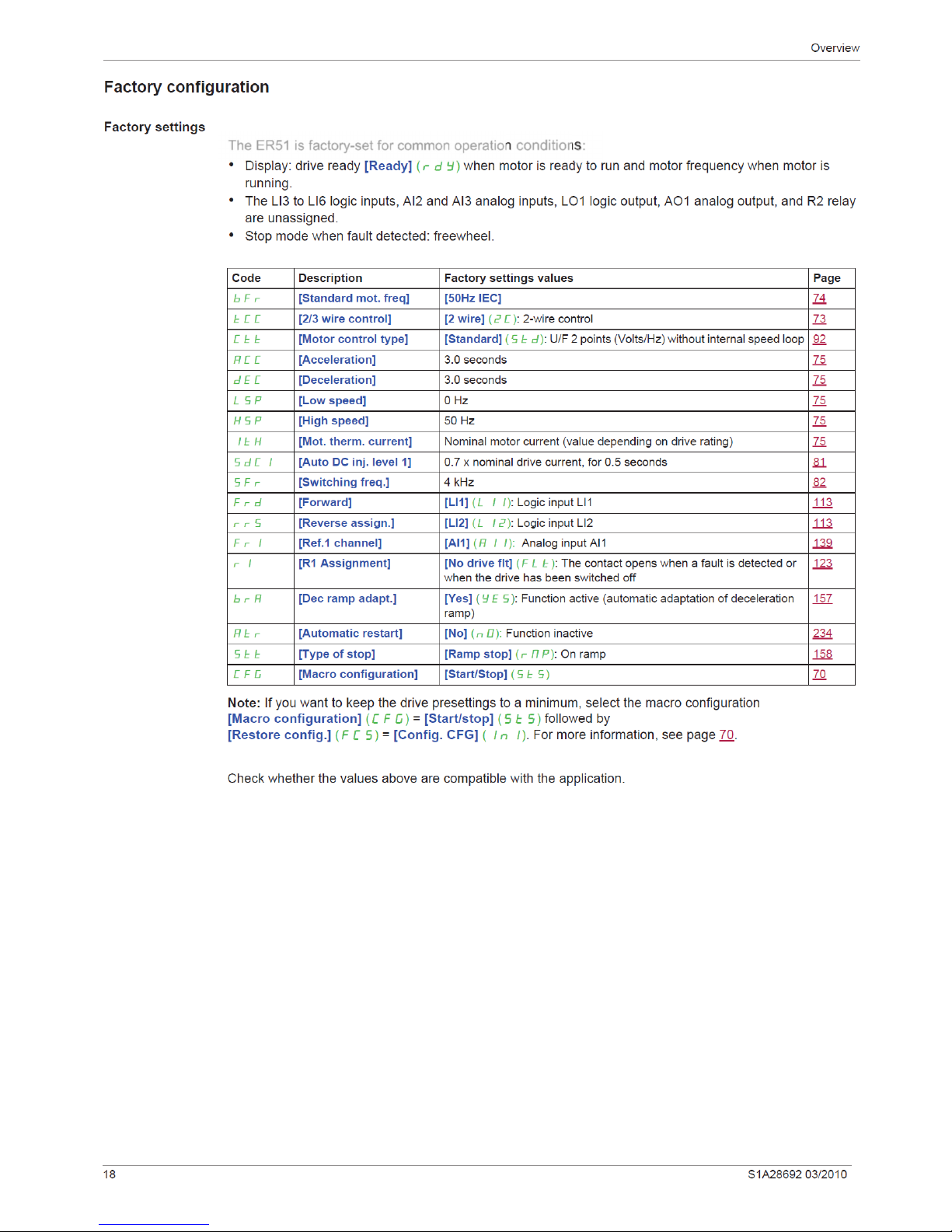
The ER51 is factory-set for common operation conditions:

Overview
S1A28692 03/2010 19
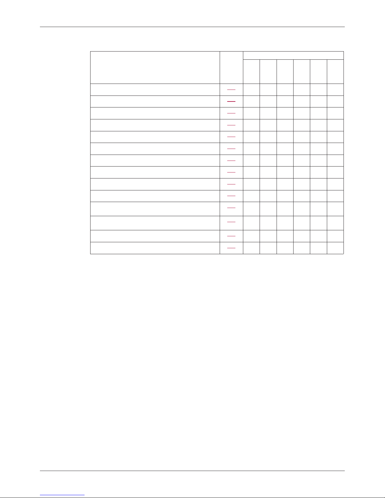
Application functions
The tables on the following pages show the combinations of functions and applications, in order to guide your
selection.
The applications in these tables relate to the following machines, in particular:
!Hoisting: cranes, overhead cranes, gantries (vertical hoisting, translation, slewing), lifting platforms
!Handling: palletizers/depalletizers, conveyors, roller tables
!Packing: carton packers, labeling machines
!Textiles: weaving looms, carding frames, washing machines, spinners, drawing frames
!Wood: automatic lathes, saws, milling
!Process
Each machine has its own special features, and the combinations listed here are neither mandatory nor
exhaustive.
Some functions are designed specifically for a particular application. In this case, the application is identified
by a tab in the margin on the relevant programming pages.
Motor control functions
Functions Page Applications
Hoisting
Handling
Packing
Textiles
Wood
Process
V/f ratio 92 b b
Sensorless flux vector control 92 b b b b b b
2-point vector control 92 b b
Open-loop synchronous motor 92 b
Output frequency up to 599 Hz 92 b b
Motor overvoltage limiting 107 b b
DC bus connection (see Installation manual) - b b
Motor fluxing using a logic input 174 bbb
Switching frequency of up to 16 kHz 82 b b
Auto-tuning 75 b b b b b b
Overview
20 S1A28692 03/2010
Functions on speed references
Functions Page Applications
Hoisting
Handling
Packing
Textiles
Wood
Process
Differential bipolar reference 116 bbb
Reference delinearization (magnifying glass effect) 119 b b
Frequency control input 139 b b
Reference switching 152 b
Reference summing 153 b
Reference subtraction 153 b
Reference multiplication 153 b
Adjustable profile ramp 155 b b
Jog operation 163 bbb
Preset speeds 165 bbb
+ speed / - speed using single action pushbuttons
(1 step)
169 b
+ speed / - speed using double action pushbuttons
(2 steps)
169 b
+/- speed around a reference 172 b b
Save reference 173 b
Table of contents
Other BLEMO DC Drive manuals


Popular DC Drive manuals by other brands


Texas Instruments
Texas Instruments DRV8811 user guide

ABB
ABB PSTX30 Service instruction

SOMFY
SOMFY J4 WT Short installation guide

SEW-Eurodrive
SEW-Eurodrive Movigear Performance MGF**-DFC-C Series operating instructions

GFA
GFA ELEKTROMAT SI 17.30 FU-30,00 installation instructions

Danfoss
Danfoss VLT AutomationDrive FC 360 operating guide

American Control Electronics
American Control Electronics Minarik MDVF03-D230-PCM quick start guide

Novoferm
Novoferm Helix S600 user manual

Newport
Newport New Focus 8712 user manual

SEW-Eurodrive
SEW-Eurodrive MOVI4R-U operating instructions

Seagate
Seagate EXOS ST3000NM007A product manual

Hitachi
Hitachi WJ200-001S instruction manual