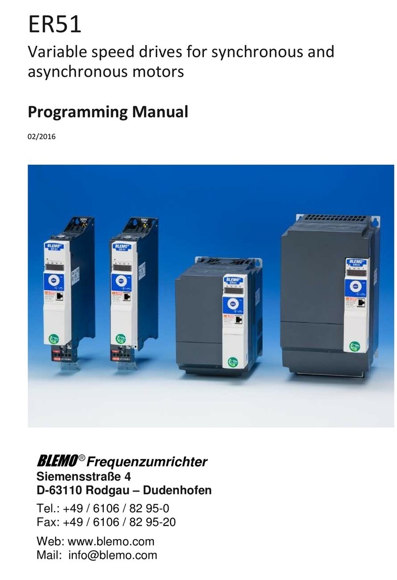
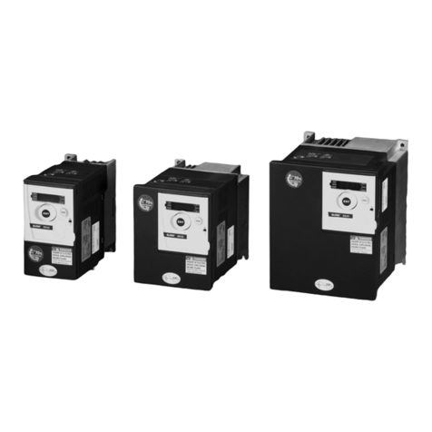
BLEMO ER21 User manual

BLEMO Frequenzumrichter
Frequency Inverter
ER21
user manual

46
ENGLISH
IT NEUTRAL POINT CONNECTION : In the event of use on a 3-phase network with a voltage greater than
460V ±10 % with an isolated or high-impedance system (IT), the internal EMC filter capacitors which are
connected to ground must be disconnected. Consult BLEMO Frequenzumrichter product support who are
the only people qualified to perform this operation.
When the speed controller is powered up, the power elements and some of the control components are
connected to the line supply. It is extremely dangerous to touch them. The cover of the speed controller
must remain closed.
In general, the speed controller power supply must be disconnected before any operation on either the
electrical or mechanical parts of the installation or machine.
After the BLEMO-ER21 has been switched off and the red LED has gone out, wait for 10 minutes before
working on the equipment. This is the time required for the capacitors to discharge.
The motor can be stopped during operation by inhibiting start commands or the speed reference while the
speed controller remains powered up. If personnel safety requires prevention of sudden restarts, this
electronic locking system is not sufficient : fit a device to remove the power circuit.
The speed controller is fitted with safety devices which, in the event of a fault, can shut down the speed
controller and consequently the motor. The motor itself may be stopped by a mechanical blockage. Finally,
voltage variations, especially line supply failures, can also cause shutdowns.
If the cause of the shutdown disappears, there is a risk of restarting which may endanger certain machines
or installations, especially those which must conform to safety regulations.
In this case the user must take precautions against the possibility of restarts, in particular by using a low
speed detector to cut off power to the speed controller if the motor performs an unprogrammed shutdown.
The products and equipment described in this document may be changed or modified at any time, either
from a technical point of view or in the way they are operated. Their description can in no way be considered
contractual.
This speed controller must be installed and set up in accordance with IEC international standards and with
national standards. Bringing the device into conformity is the responsibility of the systems integrator who
must observe the European Union directives, especially the EMC directive.
The specifications contained in this document must be applied in order to comply with the essential
requirements of the EMC directive.
The BLEMO-ER21 must be considered as a component : it is neither a machine nor a device ready for use
in accordance with European directives (machinery directive and electromagnetic compatibility directive).
It is the responsibility of the end user to ensure that the machine meets these standards.

49
ENGLISH
Table of Contents
Steps for Setting Up the Speed Controller _____________________________________________ 50
Factory Configuration _____________________________________________________________ 51
Speed Controller References _______________________________________________________ 52
Mounting _______________________________________________________________________ 54
Wiring _________________________________________________________________________ 57
Basic Functions__________________________________________________________________ 64
Configurable I/O Application Functions________________________________________________ 65
Setup - Preliminary Recommendations________________________________________________ 71
Programming ___________________________________________________________________ 72
Local control option_______________________________________________________________ 74
Remote Display Module Option _____________________________________________________ 75
Configuration____________________________________________________________________ 76
Settings________________________________________________________________________ 84
Maintenance ____________________________________________________________________ 89
Faults - Causes - Remedies ________________________________________________________ 90
Configuration/Settings Tables_______________________________________________________ 92

50
ENGLISH
Steps for Setting Up the Speed Controller
1 - Delivery of the speed controller
• Check that the speed controller reference printed on the label is the same as that on the delivery note
corresponding to the purchase order.
• Remove the BLEMO-ER21 from its packaging and check that it has not been damaged in transit.
2 - Fit the speed controller and attach its labels (page 51)
3 - Connect the following to the speed controller :
• The line supply, ensuring that it is
volt free
• The motor, ensuring that the terminal configuration corresponds to the supply voltage
• The control via the logic inputs
• The speed reference via the logic or analog inputs
4 - Switch on the speed controller, but do not give a run command
5 - Configure :
• The nominal frequency (bFr) of the motor, if it is other than 50 Hz
• The parameters of the I/O menu, and drC menus but if the factory configuration of the speed controller
is not suitable for the application
6 - Set the following in the Set menu :
If the speed controller factory settings are not suitable :
• The acceleration (ACC) and deceleration (dEC) ramps
• The minimum (LSP) and maximum (HSP) speeds
• The motor thermal protection current (ItH)
• Other parameters as required, if the factory configuration has been changed
7 - Start the speed controller
Practical recommendations
• To help with programming the speed controller, fill in the configuration and settings tables (page 92),
in particular when the factory configuration has been changed.
• Programming the BLEMO-ER21 can be made easier by internal sequence selections and interlocks.
In order to gain the maximum benefit from this, it is recommended that the menus are accessed in the
following order :
1) - I/O 2) - drC 3) - Set
Not all steps are necessary in every case.
Caution : A check must be made to ensure that the functions which have been programmed
are compatible with the wiring layout used.

51
ENGLISH
Factory Configuration
Factory settings
The BLEMO-ER21 is factory-set for the most common operating conditions:
- Display : speed controller ready (when stopped), motor frequency (when running)
- Line supply : 50 Hz.
- Motor voltage : 230 V or 400 V, depending on product
- Ramps : 3 seconds
- Low speed : 0 Hz
- High speed : 50 Hz.
- Frequency loop gain : standard
- Motor thermal current = nominal speed controller current
- Standstill injection braking current = 0.7 x nominal speed controller current, for 0.5 seconds
- Constant torque operation, with sensorless flux vector control
- Automatic adaptation of the deceleration ramp in the event of overvoltage on braking
- Switching frequency 4 kHz
- Logic inputs :
• LI1, LI2 : 2 directions of operation, 2-wire control
• LI3, LI4 : 4 preset speeds (0 Hz, 10 Hz, 15 Hz, 50 Hz)
- Analog inputs :
• AI1 (0 + 10 V) : speed reference
• AI2 (0 + 10 V) or AIC (0, 20 mA) : summing AI1
- Relay R2 :
• speed reference reached
- Analog output AO (0 - 20 mA) :
• motor frequency
If the above values are compatible with the application, the speed controller can be used without
changing the settings.
Labels
The speed controller is supplied with labels which are stored under the hinged cover :
• 1 label fixed inside the hinged cover : wiring diagram
• 3 self-adhesive labels to be fixed near the speed controller if required : programming of the
main parameters, meaning of the fault codes and customer settings (blank label).

52
ENGLISH
Speed Controller References
Single phase supply voltage (1) U1...U2 : 200…240 V 50/60 Hz
3-phase supply voltage (1) U1...U2 : 200…230 V 50/60 Hz
3-phase supply voltage (1) U1...U2 : 380…500 V 50/60 Hz
Motor Line supply BLEMO-ER21-...-K
Power
indicated on
plate (2)
Line
current (3) Max.
prosp.
line Isc
Line
current Max.
transient
current (4)
Power
dissipated
at nominal
load
Reference
at U 1 at U 2
kW HP A A kA A A W
0.37 0.5 7.3 6.1 1 3.3 3.6 32
ER21-0.37K
0.75 1 9.8 8.2 1 4.8 6 45
ER21-0.75K
1.5 2 16 13.5 1 7.8 10.9 75
ER21-1.5K
2.2 3 22.1 18.6 1 11 15 107
ER21-2.2K
3 - 17.6 15.4 5 13.7 18.5 116
ER21-3.0K
4 5 21.9 19.1 5 17.5 24.6 160
ER21-4.0K
5.5 7.5 38 33.2 22 27.5 38 250
ER21-5.5K
7.5 10 43.5 36.6 22 33 49.5 343
ER21-7.5K
Motor Line supply BLEMO-ER21-...-K
Power
indicated on
plate (2)
Line
current (3) Max.
prosp.
line Isc
Line
current Max.
transient
current (4)
Power
dissipated
at nominal
load
Reference
at U 1 at U 2 at 380
to 460V at 500V
kW HP A A kA A A A W
0.75 1 3.9 3.5 5 2.3 2.1 3.5 33
ER21-0.75/4K
1.5 2 6.5 5.7 5 4.1 3.8 6.2 61
ER21-1.5/4K
2.2 3 8.4 7.5 5 5.5 5.1 8.3 81
ER21-2.2/4K
3 - 10.3 9.1 5 7.1 6.5 10.6 100
ER21-3.0/4K
4 5 13 11.8 5 9.5 8.7 14.3 131
ER21-4.0/4K
5.5 7.5 22.1 20.4 22 14.3 13.2 21.5 215
ER21-5.5/4K
7.5 10 25.8 23.7 22 17 15.6 25.5 281
ER21-7.5/4K
11 15 39.3 35.9 22 27.7 25.5 41.6 401
ER21-11.0/4K
15 20 45 40.8 22 33 30.4 49.5 543
ER21-15.0/4K

53
ENGLISH
Speed Controller References
(1) Nominal supply voltages : min. U1, max. U2.
(2) These power ratings are for a maximum switching frequency of 4 kHz, in continuous operation. The
switching frequency is adjustable from 2 to 15 kHz.
Above 4 kHz derate the nominal speed controller current. The nominal motor current should not exceed
this value :
• Up to 12 kHz derate by 10%
• Above 12 kHz derate by 20%.
(3) Typical value for a 4-pole motor and a maximum switching frequency of 4 kHz, with no additional line
choke.
(4) For 60 seconds.

54
ENGLISH
Mounting
Dimensions and weights
Mounting recommendations
Install the unit vertically, at ± 10°.
Do not place it close to heating elements.
Leave sufficient free space to ensure that the air required for cooling purposes can circulate from the
bottom to the top of the unit.
BLEMO-ER21-...-K
a
mm b
mm c
mm G
mm H
mm 2 Ø
mm 4 Ø
mm weight
kg
-0.37K, -0.75K
105 130 140 93 118 5 1.8
-1.5K, -0.75/4K, -1.5/4K
130 150 150 118 138 5 2.5
-2.2K, -3.0K, -4.0K, -2.2/4K, -3.0/4K, -4.0/4K
140 195 163 126 182 5 3.8
-5.5K, -7.5K, -5.5/4K, -7.5/4K
200 270 170 180 255 6 6.1
-11.0/4K, -15.0/4K
245 330 195 225 315 6 9.6

55
ENGLISH
Mounting
Mounting and Temperature Conditions
Free space in front of the unit : 10 mm minimum.
• from -10°C to 40°C :
• d >= 50 mm : no special precautions.
• d = 0 (speed controllers mounted side by side) : remove the protective cover from
the top of the speed controller, as shown below (the degree of protection becomes
IP20).
• from 40°C to 50°C :• d >= 50 mm : remove the prot ective cover from the top of the speed controller, as
shown below (the degree of protection becomes IP20). If the cover is left on, derate
the nominal speed controller currentnominal speed controller current by 2.2 % for
every °C above 40°C.
• d = 0 : remove the protective cover from the top of the speed controller, as shown
below (the degree of protection becomes IP20), and derate the nominal speed
controller current by 2.2 % for every °C above 40°C .
• from 50°C to 60°C :• d >= 50 mm : remove the prot ective cover from the top of the speed controller, as
shown below (the degree of protection becomes IP20), and derate the nominal
speed controller current by 3 % for every °C above 50°C.

56
ENGLISH
Mounting
Electromagnetic compatibility
EMC plate supplied with the speed controller
Fit the EMC plate used for equipotential earthing on the holes of the
BLEMO-ER21 heatsink using the 2 screws provided, as shown in
the drawing opposite.
BLEMO-ER21-...-K ∆b
mm Ø
mm
-0.37K, -0.75K, -1.5K,
-2.2K, -3.0K, -4.0K,
-0.75/4K, -1.5/4K, -2.2/4K,
-3.0/4K, -4.0/4K
48 4
-5.5K, -7.5K,
-5.5/4K, -7.5/4K, -11.0/4K,
-15.0/4K
79 4
4 Ø screws for fixing
EMC clamps

57
ENGLISH
Wiring
Access to terminals
To access the terminals, undo the screws on the cover and tilt.
Diagram : Example showing ER21-0.37K
The speed controllers have a
removable plastic cable gland
with knock-outs for running
cables through, if required
(control and braking resistor).
1
- Control
2
- Power (1 or 2 terminals depending on the rating)
3
- Ground screw for motor cable (on low ratings only)
Power terminals
Specifications of power terminals
BLEMO-ER21-...-K Maximum connection capacity Tightening torque in Nm
AWG mm
2
-0.37K, -0.75K AWG 14 2.5 0.8
-1.5K, -0.75/4K, -1.5/4K AWG 12 3 1.2
-2.2K, -3.0K, -4.0K,
-2.2/4K, -3.0/4K, -4.0/4K AWG 10 5 1.2
-5.5K, -7.5K,
-5.5/4K, -7.5/4K AWG 5 16 2.5
-11.0/4K, -15.0/4K AWG 3 25 4.5

58
ENGLISH
Wiring
Functions of power terminals
Arrangement of the power terminals
Do not remove the connector linking terminals P0 and PA.
Terminal Function For BLEMO-ER21-...-K
BLEMO-ER21 ground terminal All ratings
L1
L2 Supply for power terminals All ratings
L3 3-phase only
PO DC bus + polarity All ratings
PA Output to braking resistor All ratings
PB Output to braking resistor All ratings
PC DC bus - polarity All ratings
U
V
WOutput to motor All ratings
BLEMO-ER21 ground terminal -5.5K, -7.5K, -5.5/4K, -7.5/4K,
-11.0/4K, -15.0/4K
ER21-0.37K, -0.75K, -1.5K, -2.2K :
ER21-3.0K, -4.0K, -0.75/4K, -1.5/4K, -2.2/4K, -3.0/4K, -4.0/4K :
ER21-5.5K, -7.5K, -5.5/4K, -7.5/4K, -11.0/4K, -15.0/4K :
For the motor ground, use the ground screw
provided on the heatsink or on the EMC plate.
For the motor ground, use the ground screw
provided on the heatsink or on the EMC plate.

59
ENGLISH
Wiring
Control terminals
Arrangement, specifications and functions of the control terminals
Terminal
Function
Electrical specifications
R1A
R1B
R1C
Common point C/O contact
(R1C) of R1 fault relay Min. switching capacity
• 10 mA for 5 V
=
Max. switching capacity on inductive load
(cos
ϕ
= 0.4 and L/R = 7 ms) :
• 1.5 A for 250 V
~
and 30 V
=
R2A
R2C N/O contact of R2
programmable relay
COM I/O common
AI1 Analog voltage input Analog input 0 + 10 V
• impedance 30 k
Ω
• resolution 0.01 V
• precision ± 4.3%, linearity ± 0.2%, of max. value
• Sampling time 4 ms max.
+10 Power supply for potentiometer
1 to 10 k
Ω
+10 V (+ 8 % - 0), 10 mA max, protected against short-circuits and
overloads
AI2
AIC
Analog voltage input
or
Analog current input
AI2 or AIC are assignable.
Use either, but not both.
Analog input 0 + 10 V, impedance 30 k
Ω
or
Analog input X - Y mA. X and Y can be programmed from 0 to 20 mA,
impedance 450
Ω
Resolution, precision, and sampling time of AI2 or AIC = AI1.
AO Analog output Output can be programmed for 0 - 20 mA or 4 - 20 mA
• Precision ± 6% of the max. value, max. load impedance 800
Ω
.
LI1
LI2
LI3
LI4
Logic inputs Programmable logic inputs
• + 24 V power supply (max. 30 V)
• Impedance 3.5 k
Ω
• State 0 if < 5 V, state 1 if > 11 V
• Sampling time 4 ms max.
+ 24 Logic input power
supply + 24 V protected against short-circuits and overloads, min. 19 V, max.
30 V. Max. customer current available 100 mA
- Maximum connection capacity
1.5 mm
2
- AWG 16
- Max. tightening torque :
0.5 Nm

60
ENGLISH
Wiring
Wiring diagram for factory settings
(1) Line choke, if used (single phase or 3-phase).
(2) Safety relay contacts, for remote indication of the speed controller status.
(3) Internal +24 V. If an external +24 V source is used, connect the 0 V from that source to the COM
terminal, and do not use the + 24 terminal on the speed controller.
Note :
Fit interference suppressors to all inductive circuits near the speed controller or coupled to the
same circuit (relays, contactors, solenoid valves, etc)
Choice of associated components :
See BLEMO-ER21 catalog.

61
ENGLISH
Wiring
Wiring recommendations
Power
Observe the cable cross-sectional areas recommended in the standards.
The speed controller must be earthed, in order to comply with regulations concerning high leakage
currents (over 3.5 mA). When the use of an upstream "residual current device" for protection is required
by the installation standards, a "type B" device must be used, which will operate even in the presence of
DC components. If the installation has several speed controllers on the same line, each controller must
be earthed separately. If necessary, fit a line choke (consult the catalogue).
Keep the power cables separate from circuits in the installation with low level signals (detectors, PLCs,
measuring apparatus, video, telephone).
Control
Keep the control circuits and the power cables apart. For control and speed reference circuits, we
recommend using shielded twisted cables with a pitch of between 25 and 50 mm, connecting the
shielding to ground at each end.

62
ENGLISH
Wiring
Electromagnetic compatibility
Principle
• Grounds between speed controller, motor and cable shielding should have "high frequency"
equipotentiality.
• Use shielded cables with shielding connected to ground at 360°at both ends for the motor cable,
braking resistor (if used) and control-command cables. Conduit or metal ducting can be used for part of
the shielding length, provided that there is no break in continuity.
• Ensure maximum separation between the power supply cable (line supply) and the motor cable.
Installation diagram

63
ENGLISH
Wiring
1 - Sheet steel grounded casing supplied with the speed controller, to be fitted as indicated on the
diagram.
2 - BLEMO-ER21
3 - Non-shielded power supply wires or cables.
4 - Non-shielded wires for the output of the safety relay contacts.
5 - Attachment and connection to ground of the shielding of cables 6, 7 and 8 as close as possible to the
speed controller :
- strip the shielding
- use cable clamps of an appropriate size on the parts from which the shielding has been stripped, to
attach them to the casing 1.
The shielding must be clamped onto the casing sufficiently tightly to create a good contact.
- types of clamp : stainless steel.
6 - Shielded cable for connecting the motor, with shielding connected to ground at both ends.
This shielding must be unbroken, and if there are intermediate terminals, they must be in EMC
shielded metal boxes.
7 - Shielded cable for connecting the control.
For applications which require a large number of conductors, small cross-sections must be used
(0.5 mm
2
).
The shielding must be connected to ground at both ends. This shielding must be unbroken, and if
there are intermediate terminals, they must be in EMC shielded metal boxes.
8 - Shielded cable for connecting the braking resistor, if used. The shielding must be connected to
ground at both ends. This shielding must be unbroken, and if there are intermediate terminals, they
must be in EMC shielded metal boxes.
9 - Ground screw for the motor cable with low ratings, as the screw on the heatsink is inaccessible.
Note :
• If an additional input filter is used, it is mounted on the speed controller, and connected directly to the
line supply by an unshielded cable. Connection 3 on the speed controller is then made using the filter
output cable.
• Although there is an HF equipotential ground connection between the speed controller, the motor and
the cable shielding, it is still necessary to connect the PE protective conductors (green-yellow) to the
appropriate terminals on each of the devices.

64
ENGLISH
Basic Functions
Fault relay, unlocking
The fault relay is energized when the speed controller is powered up and there is no fault. It has a
common point C/O contact.
The speed controller is unlocked after a fault by the following operations :
- Powering down the speed controller until the display and the red LED extinguish, then powering up
again
- Automatically when the "automatic restart" function has been activated
- Via a logic input when this input is assigned to the "fault reset" function
Speed controller thermal protection
Functions :
Thermal protection by thermistor fitted on the heatsink or integrated in the power module.
Indirect protection of the speed controller against overloads by current limit. Typical tripping points :
- motor current = 185 % of nominal speed controller current : 2 seconds
- motor current = maximum speed controller transient current : 60 seconds.
Speed controller ventilation
The fan is powered automatically when the speed controller is unlocked (operating direction +
reference). It is powered down a few seconds after the speed controller is locked (motor speed < 0.5 Hz
and injection braking completed).
Motor thermal protection
Function :
Thermal protection by calculating I
2
t
Caution : The motor thermal state memory is reset to zero when the speed controller is switched off.

65
ENGLISH
Configurable I/O Application Functions
Logic input application functions
Direction of operation : forward / reverse
Reverse operation can be disabled for applications with a single direction of motor rotation.
2-wire control :
Run (forward or reverse) and stop are controlled by the same logic input, for which state 1 (run) or 0
(stop) is taken into account.
On power-up or a manual fault reset or after a stop command, the motor can only be powered once the
"forward", "reverse" and "DC injection stop" commands have been reset. If the automatic restart function
is configured (parameter Atr in the drC menu), these commands are taken into account without a reset
being necessary.
3-wire control :
Run (forward or reverse) and stop are controlled by 2 different logic inputs.
LI1 is always assigned to the stop function. Stop occurs on opening (state 0).
The pulse on the run input is memorized until the stop input is opened.
On power-up or a manual fault reset or after a stop command, the motor can only be powered once the
"forward", "reverse" and "DC injection stop" commands have been reset.
Ramp switching :
1st ramp : ACC, DEC ; 2nd ramp : AC2, DE2
This can be activated in 2 ways :
- By activating a logic input LIx or by detection of an adjustable frequency threshold Frt.
Step by step operation (JOG):
Low speed operation pulse
If the JOG contact is closed, then the operating direction contact activated, the ramp is 0.1 s whatever
the ACC, dEC, AC2 and dE2 settings. If the operating direction contact is closed, then the JOG contact
activated, the configured ramps are used.
The minimum time between 2 JOG operations is 0.5 seconds
Parameter which can be accessed in the adjust menu :
- JOG speed

66
ENGLISH
Configurable I/O Application Functions
Preset speeds
2, 4 or 8 speeds can be preset, and requiring 1, 2, or 3 logic inputs respectively.
The following assignment order must be observed : PS2 (LIx), then PS4 (LIy), then PS8 (LIz).
To unassign the logic inputs, the following order must be observed : PS8 (LIz), then PS4 (LIy), then PS2
(LIx).
Reference switching :
Two references are switched (AI1 reference and AI2 or AIC reference) by a command on a logic input.
This function automatically assigns AI2 or AIC to speed reference 2
Connection diagram Contact open, reference = AI2 or AIC
Contact closed, reference = AI1
If AI2/AIC is assigned to the PI function, operation combines
both functions, (see page 68)
2 preset speeds 4 preset speeds 8 preset speeds
Assign : LIx to PS2 Assign : LIx to PS2, then LIy to PS4 Assign : LIx to PS2, then
LIy to PS4, then LIz to PS8
LIx speed reference LIy LIx speed reference LIz LIy LIx speed reference
0 Reference (min = LSP) 0 0 Reference (min = LSP) 0 0 0 Reference (min = LSP)
1 HSP 0 1 SP2 0 0 1 SP2
1 0 SP3 0 1 0 SP3
1 1 HSP 0 1 1 SP4
1 0 0 SP5
1 0 1 SP6
1 1 0 SP7
1 1 1 HSP
Table of contents
Other BLEMO DC Drive manuals
Popular DC Drive manuals by other brands
Lenze
Lenze E82ZAFBC201 Mounting instructions
Rockwell Automation
Rockwell Automation Allen-Bradley PowerFlex 40 FRN Series user manual
SOMFY
SOMFY ilmo2 50 WT instructions
iRZ
iRZ 500 Series installation manual

Invertek Drives
Invertek Drives OPTISTICK 2 user guide
SYSTEM Electronics
SYSTEM Electronics ETC-QUAD UL user manual
