Blichmann Engineering AutoSparge Quick guide

AutoSparge
Operation, Assembly & Maintenance Manual
Congratulations on your purchase and thank you for selecting the AutoSpargeTM lauter tun level control from Blichmann
Engineering. We are confident that it will provide you years of service and many gallons of outstanding beer. This manual
will familiarize you with the assembly and use of the lauter tun level control.
**** PLEASE READ THOROUGHLY PRIOR TO USE FOR IMPORTANT SAFETY INFORMATION ****
IMPORTANT !!
Caution:
Warning:
Sections labeled “Caution” can lead to equipment damage or unsatisfactory performance of the
equipment. Please read these sections thoroughly. If you have any questions, contact your retailer or
Blichmann Engineering (www.BlichmannEngineering.com) before use.
Sections labeled “Warning” can lead to serious injury or death if not followed. Please read these
thoroughly and understand them completely before use. If you do not understand them or have any
questions, contact your retailer or Blichmann Engineering (www.BlichmannEngineering.com) before use.
Assembly & Installation:
Ensure you have all the parts included in Fig. 1. This product is shipped disassembled. Please contact your Retailer if any
parts are missing.
Fig. 1
Installing the Float Ball
Pinch hose Push hose in ball
Pull hose Ready to use

2
Installation Procedure
The AutoSpargetm can be installed in nearly any pot or cooler with a minimum of 12” of inside clearance for the float to
move. Installation of the product in a brew pot merely requires a 13/16” mounting hole be drilled or punched in the pot. A
7/8” hole will also work, but is a bit on the big side.
Installation in a brew pot:
Blichmann Engineering offers a punching service for BoilerMaker
tm
pots for a nominal fee when purchased new from the
factory. We do not punch other pots, or accept pots back to us for punching. We offer 6 different locations to
accommodate your installation. See our web page for details.
To install in your pot, simply mark your desired location approximately 2” from the top lip of the pot and drill a 3/16 pilot
hole. Then use a step drill and enlarge the hole to 13/16”. Step drills are available through most hardware/home
improvement centers or through McMaster.com (part# 8841A24 or 89315A42 for TiN coated). Step drills produce a
perfectly round hole and are great for use in sheet metal. Alternately, a knockout punch (McMaster.com part 3449A999)
can be used. Hole saws are another tool that can be used, however they produce a rougher hole and sometimes catch in
sheet metal so are harder to use. Fig 2 shows a hole being drilled with a step drill. Note that the gasket goes on the INSIDE
of the pot.
Installation into a cooler: is a bit more work, but is still a simple process.
(1) Drill a ¼” pilot hole all the way through the cooler from the
outside. It is important to drill completely through the cooler so all
holes are concentric.
(2) Using a 2” to 2-1/4” hole saw, cut through the OUTER wall of the pot ONLY. DO
NOT drill all the way through. This will allow clearance for your hose fittings.
TIP: Use the hole saw in REVERSE (counterclockwise) to prevent it from grabbing
the plastic and sawing through too quickly.
Fig. 3
Fig. 2

3
(3) After drilling, remove the plug and foam. If desired, you can put a layer of
silicone sealant on the foam to keep liquids from soaking into the foam insulation.
(4) Use a step drill and enlarge the pilot hole on the inside wall to 13/16”.
(5) Install the AutoSpargetm as shown here. Tighten finger tight, and then rotate
the valve assembly from the inside of the cooler while holding the nut still with
your fingers to tighten it. Alternately, a 1-1/16” deep well socket wrench can be
used to tighten the nut.
(6) This figure shows the AutoSpargetm installed in a 10 gal
Rubbermaid cooler.
(7) At this time, install your preferred hose fitting. Shown here is a Blichmann
Engineering QuickConnectortm. But any ½” NPT connector will work.
This concludes the installation instructions for your AutoSpargetm lauter tun level control.

4
Connect the hot liquor to the inlet of the AutoSpargetm (the ½” NPT end)
via gravity feed or with a pump. Do not exceed 10 PSI to prevent leaking
past the float valve. Fig 3 shows a typical gravity connection.
Caution: Make sure the valve on your tank or the pump is in the OFF
position or the hot liquor will flow into your
mash/lauter tun!
Prior to doughing in, loosen the adjustment knob thumb screw (see Fig 4) and move the float to the fully upward position
and hang the hose on the outside of the pot so they aren’t in your way while you add your grains. After filling your mash
tun and doughing in your grains, use the adjustment knob to set the float position. Simply loosen the thumb screw and
rotate the float arm to the desired position and tighten the screw finger tight. Lift up on the stainless float until it stops –
this will be the liquid level control point will be where the float shuts off the flow (about the middle of the ball). If it is too
high or would hit the lid of your pot, move it to a lower position.
Caution: If the stainless float ball hits the lid of your mash tun it will prevent the float from shutting off the flow and will
overflow your pot!
Level adjustment: adjust the desired position of the liquid by loosening the thumbscrew and repositioning it using the
teeth on the arm faces. It is not necessary to completely remove the screw and risk dropping it into the mash. If you
cannot find an acceptable position you may remove the thumb screw completely and flip the float arm over using the set
of teeth on the opposite side. They are rotated ½ tooth on each side to allow for adjustments in 7.5 deg increments.
Fig 4 shows the float during a mash. Note that in this pic the unit is being used in a RIMS system so wort may be flowing.
Also note that the outlet hose with the foam float is simply laid on top of the grain bed where it will float and maintain a
gently flow over the top of the mash. Fig 5 shows the flow during lauter. Note the gentle distribution or hot liquor over
the grain bed.
Tip: while it is not very common due to the large passages in the valve, grain particles may, on occasion, get stuck. To clear
them, simply press down on the ball momentarily with a spoon to fully open the valve and the flow will eject the grain
particles.
Operation:
The AutoSpargetm is elegantly simple to operate. It does not rely on complicated sprinkling systems that aerate the hot
liquor and require constant monitoring to keep from overflowing or running dry.
The AutoSpargetm, on the other hand, does the level monitoring for you automatically. It gently distributes the hot liquor
over the grain bed while maintaining 1-2” of hot liquor over the grain bed at all times to reduce channeling (shunting) in
the grain bed. The stainless ball simply floats on top of the liquid in your tun and as the level raises it closes a valve internal
to the brass body and reduces the flow of water entering the tun. Conversely, if the level is
lowering, it opens the valve letting it enter the tun at a faster rate.
Fig. 3

5
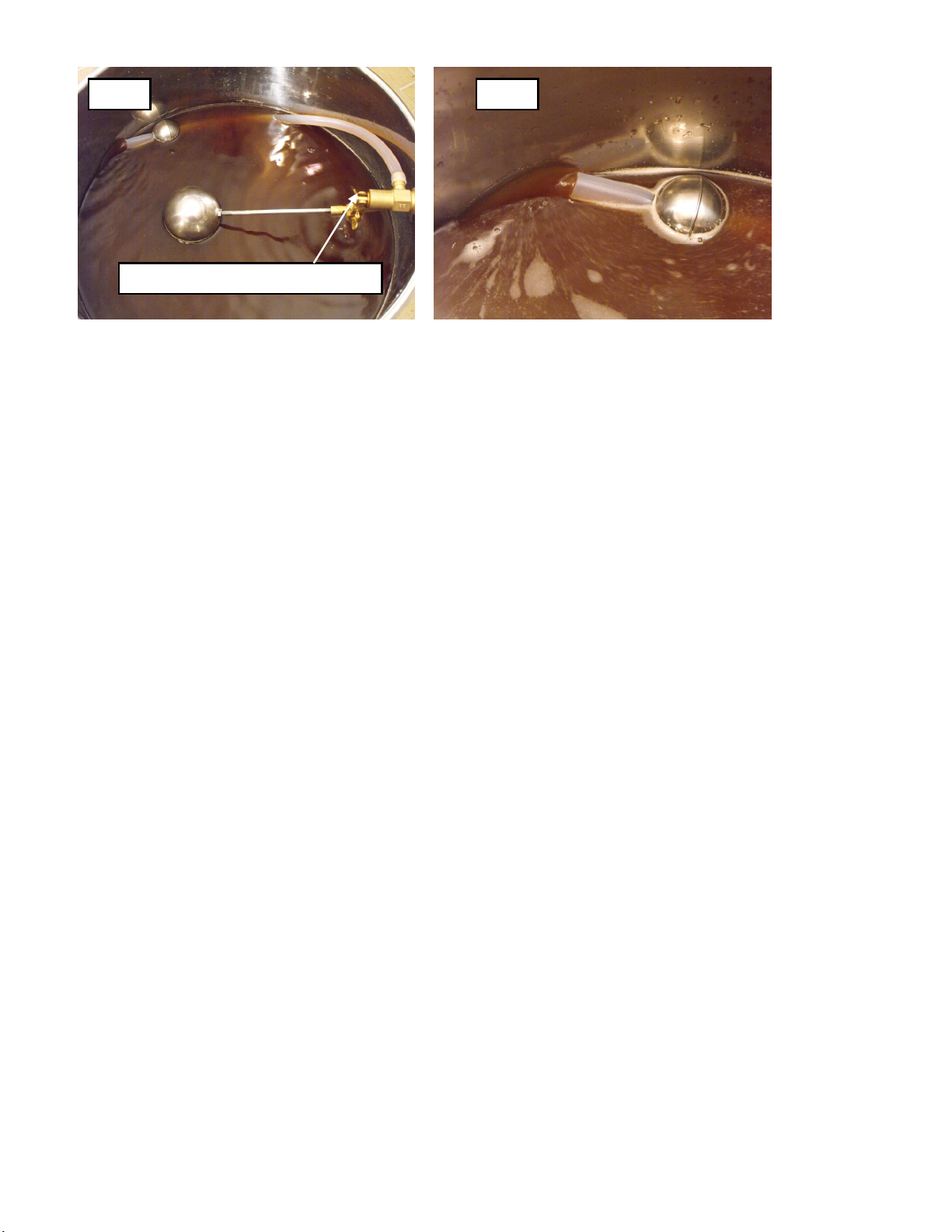
Tip: We do recommend that you periodically rake the top 1/3 of the mash during lauter about every 15 min to maintain a
smooth efficient lauter process. Raking the top of the mash will not disturb the lower part of the grain bed and the wort
will remain clear throughout the lauter.
When you have finished your mash, simply turn on the hot liquor tank valve and/or pump to the full open position. Then
open the mash/lauter tun valve to the desired wort drain rate. That’s it! The AutoSparge
tm
will automatically let more hot
liquor into the tun to compensate for the rate at which you’re draining wort into your brew pot. Note that hot liquor may
flow quickly at first until you reach the level control point and then the valve will slow the flow to match the drain rate. As
you change the rate you’re draining, the AutoSparge
tm
will automatically match it, maintaining a constant liquid level over
your grain bed.
Caution: The AutoSparge
tm
is NOT intended for unattended operation or for use as an automated pot filler. City/well water
pressure will NOT be shut off by the AutoSparge!! A max pressure if 10 PSI is allowed. This is plenty for most gravity and
small magnetic drive pump installations.
Maintenance
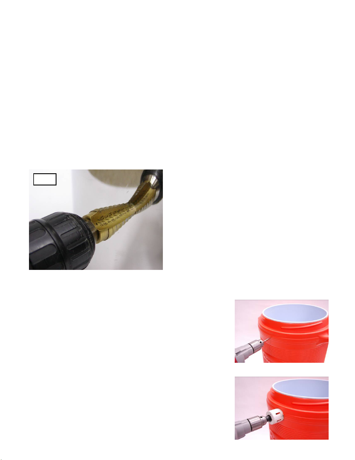
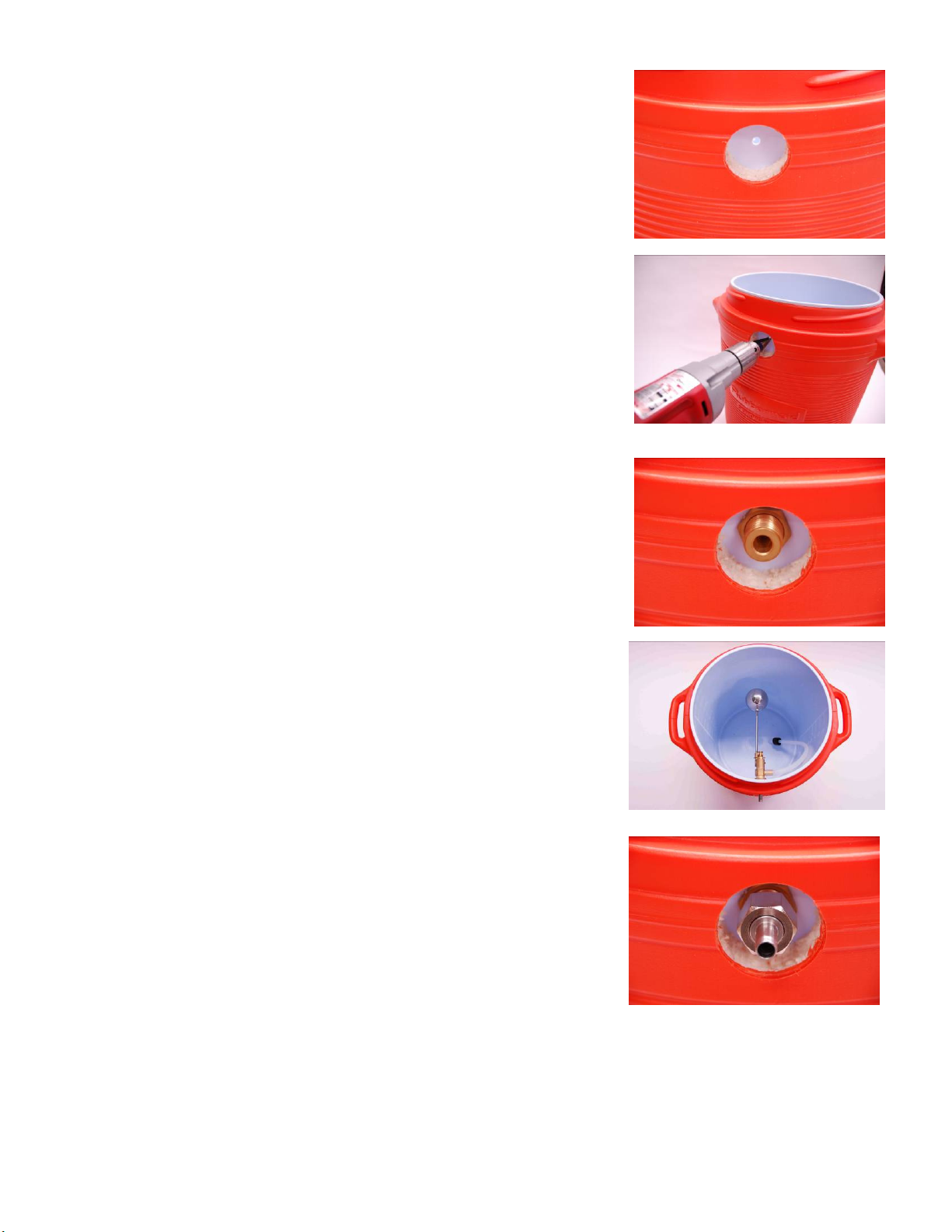
Clean the AutoSparge
tm
with any brass/stainless compatible cleaner and allow to dry thoroughly. It is not necessary to
remove the AutoSparge
tm
from the pot for cleaning, although removing the ball/arm assembly (remove the thumb screw)
will make cleaning the inside of your mash/lauter tun easier.
Blichmann Engineering Product Warranty
Fig. 5
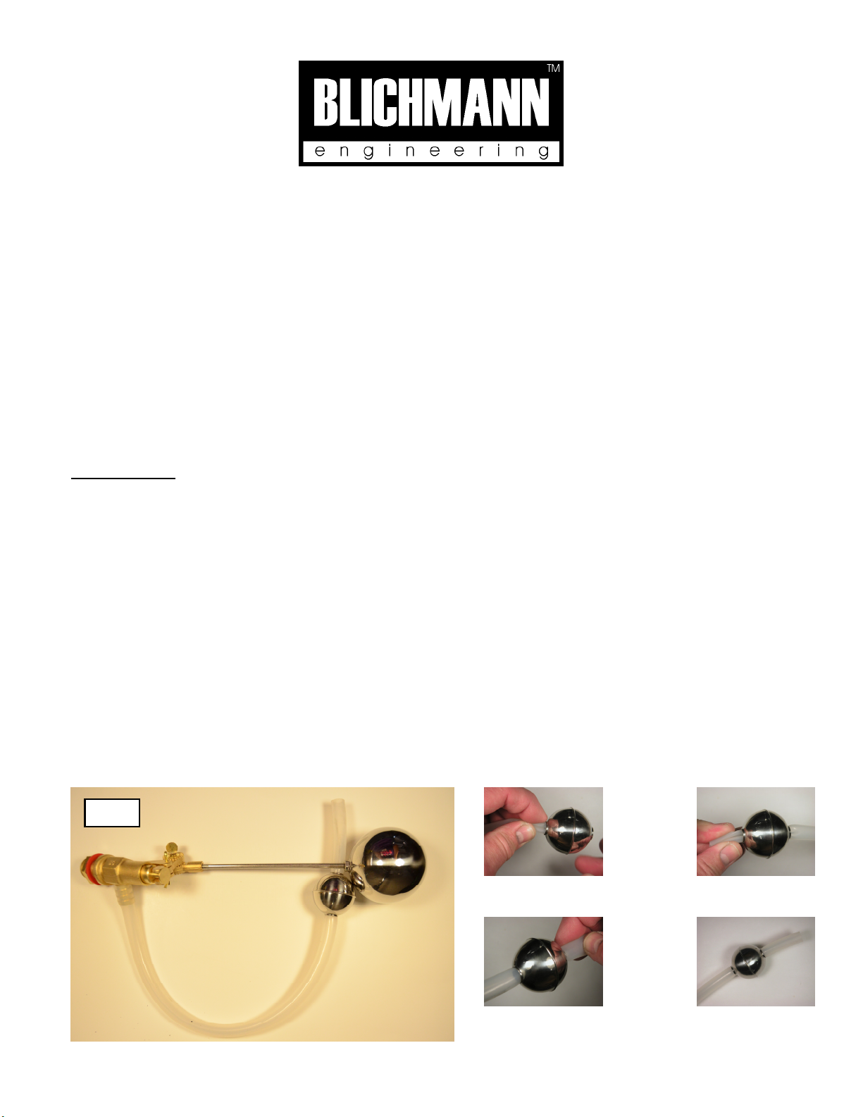
Float adjustment thumb screw
Fig.
4
A. Limited Warranty
1. Blichmann Engineering warrants to the original purchaser that this product will be free from manufacturing defects in material and workmanship for a period of one (1) year from the
date of purchase by the customer. Proof of purchase is required. Blichmann Engineering’s obligation to repair or replace defective materials or workmanship is the sole obligation of
Blichmann Engineering under this limited warranty.
2. The limited warranty covers only those defects that arise as a result of normal use of the product and does not cover any other problems, including, but not limited to, those that arise
as a result of:
a. Improper maintenance or modification;
b. Damage due to incorrect voltage or improper wiring by customer;
c. Operation outside of the product’s specifications;
d. Carelessness or neglect to operate the product in accordance with instructions provided with the product;
e. Damaging the tamper label on the product;
f. Damage by over-tightening the fasteners;
g. Failure to follow cleaning and / or maintenance procedures; or
h. Exceeding published operational temperatures.
3. Blichmann Engineering reserves the right to request delivery of the defective component for inspection before processing the warranty claim. If Blichmann Engineering receives,
during the applicable warranty period, notice of a defect in any component that is covered by the warranty, Blichmann Engineering shall either repair or replace the defective
component with a new or rebuilt component at Blichmann Engineering’s option.
4. Blichmann Engineering must be notified within seven (7) days of the delivery date of any shipping damage. Customer is responsible for shipping damage outside of this time period.
Approval for return must be provided by Blichmann Engineering prior to any return. Customer is responsible for keeping all original packaging material for warranty returns.
Blichmann Engineering is not responsible for damage from improperly packaged warranty returns, and these repair costs will be the sole responsibility of the customer. Shipping
costs for warranty returns are covered only for the contiguous United States.
5. Blichmann Engineering’s limited warranty is valid in any country where the product is distributed.

6
AutoSparge
tm
Owners Manual – V2
Blichmann Engineering, LLC 2010
B. Limitations of Warranty
1. Any implied warranty that is found to arise by way of state or federal law, including any implied warranty of merchantability or any implied warranty of fitness, is limited in
duration to the terms of this limited warranty and is limited in scope of coverage to this warranty. Blichmann Engineering disclaims any express or implied warranty, including
any implied warranty of fitness for a particular purpose or merchantability, on items excluded from coverage as set forth in this limited warranty.
2. Blichmann Engineering makes no warranty of any nature beyond that contained in this limited warranty. No one has authority to enlarge, amend, or modify this limited
warranty, and Blichmann Engineering does not authorize anyone to create any other obligation for it regarding this product.
3. Blichmann Engineering is not responsible for any representation, promise, or warranty made by any independent dealer or other person beyond what is expressly stated in
this limited warranty. Any selling or servicing dealer is not Blichmann Engineering’s agent, but an independent entity.
C. Limitations of Liability
1. The remedies provided in this warranty are the customer’s sole and exclusive remedies.
2. Except for the obligations specifically set forth in this warranty, in no event shall Blichmann Engineering be liable for direct, indirect, special, incidental, or consequential
damages, whether based on contract, tort, or any other legal theory and whether or not advised of the possibility of such damages.
3. This warranty does not cover, and in no event shall Blichmann Engineering be liable for, travel, lodging, or any other expense incurred due to manufacturing defects in
material and workmanship, or any other reason.
4. Any performance of repairs after the warranty coverage period has expired or performance of repairs regarding anything excluded from coverage after this limited
warranty shall be considered good-will repairs and they will not alter the terms of this limited warranty, or extend any warranty coverage period.
5. Venue for any legal proceedings relating to or arising out of this warranty shall be in Tippecanoe County, Indiana, United States, which courts will have exclusive
jurisdiction.
D. Local Law
1. This warranty gives the customer specific legal rights. The customer may also have other rights that vary from state to state in the United States or other countries.
2. To the extent that this warranty is inconsistent with local law, it shall be deemed modified, only to the extent necessary to be consistent with such local law.
This product uses food grade materials anywhere the product touches the beverage.
Warning: This product contains or may contain chemical(s) known to the State of California to cause cancer, birth defects, or other reproductive harm.
Table of contents
Other Blichmann Engineering Kitchen Appliance manuals