Grain Mill © Blichmann Engineering, LLC 2020
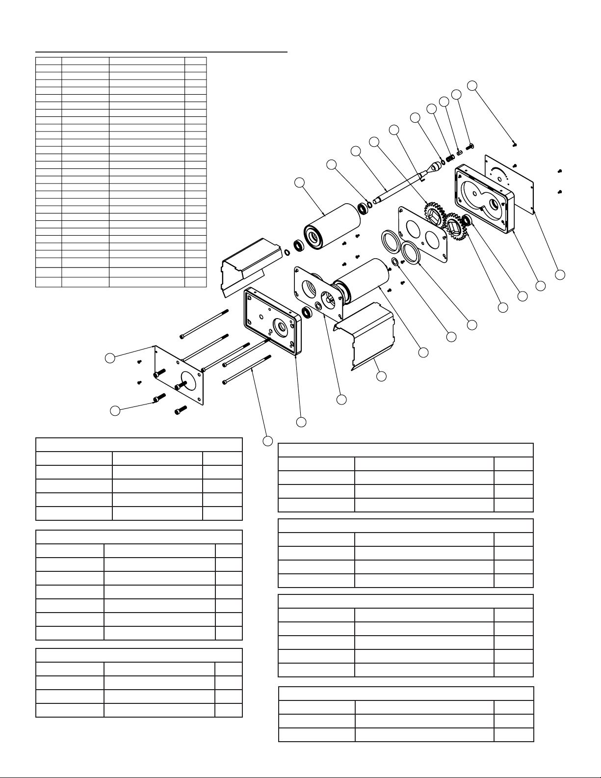
For replacement parts, visit: blichmannengineering.com/genuine-replacement-parts 7
Blichmann Engineering Product Warranty
A. Limited Warranty
1. Blichmann Engineering warrants to the original purchaser that this product will be free from manufacturing defects in material and workmanship for a period of one (1) year from the date of purchase by the customer. Proof of
purchase is required. Blichmann Engineering’s obligation to repair or replace defective materials or workmanship is the sole obligation of Blichmann Engineering under this limited warranty.
2. The limited warranty covers only those defects that arise as a result of normal use of the product and does not cover any other problems, including, but not limited to, those that arise as a
result of:
a. Improper maintenance or modication;
b. Damage due to incorrect voltage or improper wiring by customer;
c. Operation outside of the product’s specications;
d. Carelessness or neglect to operate the product in accordance with instructions provided with the product;
e. Damaging the tamper label on the product;
f. Damage by over-tightening the fasteners;
g. Failure to follow cleaning and / or maintenance procedures; or
h. Exceeding published operational temperatures.
3. Blichmann Engineering reserves the right to request delivery of the defective component for inspection before processing the warranty claim. If Blichmann Engineering receives, during the applicable warranty period, notice
of a defect in any component that is covered by the warranty, Blichmann Engineering shall either repair or replace the defective component with a new or rebuilt component at Blichmann Engineering’s option.
4. Blichmann Engineering must be notied within seven (7) days of the delivery date of any shipping damage. Customer is responsible for shipping damage outside of this time period. Approval for return must be provided by
Blichmann Engineering prior to any return. Customer is responsible for keeping all original packaging material for warranty returns. Blichmann Engineering is not responsible for damage from improperly packaged warranty
returns, and these repair costs will be the sole responsibility of the customer. Shipping costs for warrantee returns are covered only for the contiguous United States.
5. Blichmann Engineering’s limited warranty is valid in any country where the product is distributed.
________________________________________
B. Limitations of Warranty
1. Any implied warranty that is found to arise by way of state or federal law, including any implied warranty of merchantability or any implied warranty of tness, is limited in duration to the terms of this limited warranty and is
limited in scope of coverage to this warranty. Blichmann Engineering disclaims any express or implied warranty, including any implied warranty of tness for a particular purpose or merchantability, on items excluded from
coverage as set forth in this limited warranty.
2. Blichmann Engineering makes no warranty of any nature beyond that contained in this limited warranty. No one has authority to enlarge, amend, or modify this limited warranty, and Blichmann Engineering does not authorize
anyone to create any other obligation for it regarding this product.
3. Blichmann Engineering is not responsible for any representation, promise, or warranty made by any independent dealer or other person beyond what is expressly stated in this limited warranty. Any selling or servicing dealer
is not Blichmann Engineering’s agent, but an independent entity.
________________________________________
C. Limitations of Liability
1. The remedies provided in this warranty are the customer’s sole and exclusive remedies.
2. Except for the obligations specically set forth in this warranty, in no event shall Blichmann Engineering be liable for direct, indirect, special, incidental, or consequential damages, whether based on contract, tort, or any other
legal theory and whether or not advised of the possibility of such damages.
3. This warranty does not cover, and in no event shall Blichmann Engineering be liable for, travel, lodging, or any other expense incurred due to manufacturing defects in material and workmanship, or any other reason.
4. Any performance of repairs after the warranty coverage period has expired or performance of repairs regarding anything excluded from coverage after this limited warranty shall be considered good-will repairs and they will
not alter the terms of this limited warranty, or extend any warranty coverage period.
5. Venue for any legal proceedings relating to or arising out of this warranty shall be in Tippecanoe County, Indiana, United States, which courts will have exclusive jurisdiction.
________________________________________
D. Local Law
1. This warranty gives the customer specic legal rights. The customer may also have other rights that vary from state to state in the United States or other countries.
2. To the extent that this warranty is inconsistent with local law, it shall be deemed modied, only to the extent necessary to be consistent with such local law.
This product uses FDA and/or NSF approved food grade materials anywhere the product touches the beverage.
Warning: This product contains or may contain chemical(s) known to the State of California to cause cancer, birth defects, or other reproductive harm.
6-1/16
6-11/16
5-1/2
6-7/8
5/16
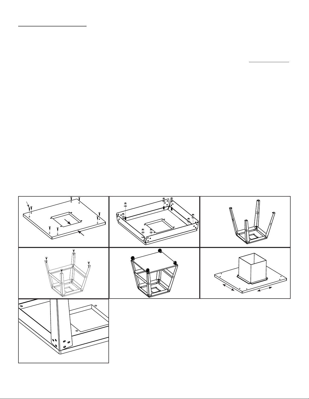
Required Cut-out
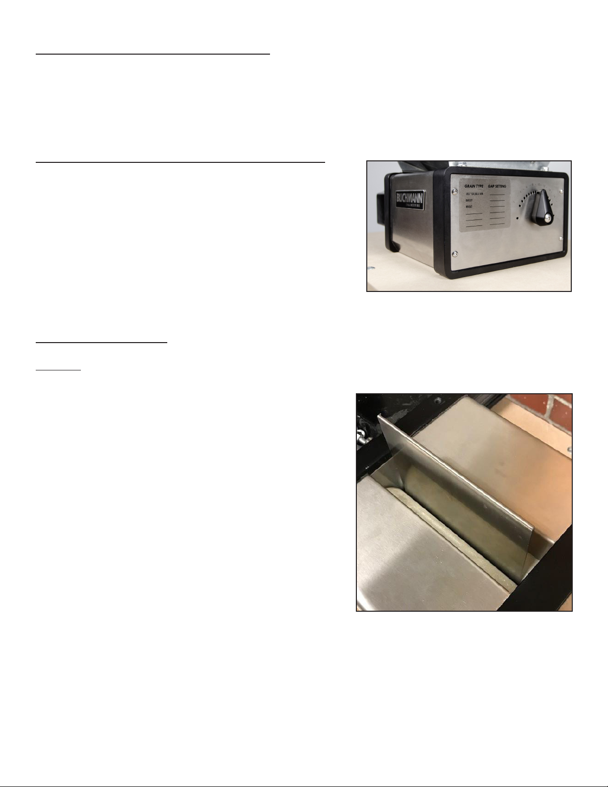
Front of Mill
NOT TO
SCALE