Blohm + Voss Oil Tools VES-HCL 350 User manual

1
Blohm+Voss Pipe Handling Equipment
VES-HCL 350 Elevator Hydraulically Operated
Part no. 613000-Y-H-F (with closing signal)
Technical Documentation
Original Instructions
Manual PN 613000-Y-H-F-D Rev 005 valid from SN 84007 , April 2012
Blohm + Voss Oil Tools

2
Improper / Unsafe Use
The tool must only be used
for the designated purpose.
When using the tool, the
rated load must never be
exceeded.
Intended use of this
manual
This manual is intended
for use by field service,
engineering, installation,
operation, and repair
personnel. Every effort has
been made to ensure the
accuracy of the information
contained herein. Blohm
+ Voss Oil Tools, will not
be held liable for errors
in this material, or for
consequences arising from
misuse of this material.
Anyone using service
procedures or tools, whether
or not recommended by
Blohm + Voss Oil Tools, must
be thoroughly satisfied that
neither personal safety nor
equipment safety will be
jeopardized.
Intellectual property
All rights retained. No part
of this document may be
reproduced in any form
(print, photocopy, microfilm
or any other procedure)
or be processed using an
electronic system without
written approval of Blohm +
Voss Oil Tools.
All information contained
in this manual is based
upon the latest product
information available at any
time of printing.
Dependent on ongoing
technical improvements
(ISO 9001) “Blohm + Voss
Oil Tools” reserves the
right to change the design
and specifications without
announcement.
The values specified in
this manual represent the
nominal values of a unit
produced in series. Slight
deviations in the case of
the individual devices are
possible.
NOTE: In the event of
problems that cannot be
solved with the aid of this
manual, please contact
one of the addresses listed
below.
Warnings and Note
WARNING: A “WARNING”
INdIcAtes AdefINIte RIsk of
equIpmeNt dAmAGe oR dANGeR to
peRsoNNel. fAIluRe to obseRve
ANd folloW pRopeR pRoceduRes
could Result IN seRIous oR fAtAl
INjuRy to peRsoNNel, sIGNIfIcANt
pRopeRty loss, oR sIGNIfIcANt
equIpmeNt dAmAGe.
NOTE: A “note” indicates
that additional information is
provided about the current
topics.
WARNING: thIs techNIcAl
documeNtAtIoN coNtAINs
INstRuctIoNs oN sAfety,
INstAllAtIoN, opeRAtIoN ANd
mAINteNANce foR the blohm +
voss oIl tools tool . Itmust
be studIed befoRe WoRkING WIth
the tool.
CE Marking
The tool complies with the
Machinery Directive
98/37/EC and 2006/42/EC
For machines containing
any hydraulic or pneumatic
powered parts, the Directive
94/9/EC “Equipment
and protective systems
in potentially explosive
atmospheres” applies.
The marking is as follows:
CE Ex II 2G T5 (hydraulic
tools) or CE Ex II 2G T6
(pneumatic tools).
Manufacturer & Agents World wide
Limited Warranty
The warranty provided will
be void if the tool is either:
1. Repaired or serviced by
a service facility which
was not authorised by
Blohm + Voss Oil Tools.
2. Replacement parts not
manufactured by Blohm
+ Voss Oil Tools are
used.
3. Modifications were made
to the tool which were
not approved by Blohm
+ Voss Oil Tools.
Blohm + Voss Oil Tools
Hermann-Blohm-Straße 2
20457 Hamburg
Germany
Phone: +49 40/3119-1826/1162
Fax: +49 40/3119-8194
oiltools@blohmvoss.com
www.blohmvoss-oiltools.com
Premier Sea & Land Pte. Ltd.
1, Scotts Road
#19-12 Shaw Centre
Singapore 228208
Republic of Singapore
Phone: +65-6734-7177
Fax: +65-6734-9115
enquiries@mtqpremier.com.sg
Blohm + Voss Oil Tools, LLC
7670 Woodway, Suite 266
Houston,
Texas 77063
United States of America
Phone: +1-713-952 0266
Fax: +1-713-952 2807
www.blohmvoss-oiltools.com
GENERAL INFORMATION

3
Warning sign PN 671638
General warning
Warning sign PN 671642
Pay attention: Apply grease at least
once a day.
Warning sign PN 611524
Danger: Do not touch.
Warning sign PN 671640-1
Pay attention: Do not place your
hands between moving parts.
Warning sign PN 671641
Pay attention: Risk of crushing.
General safety issues
WARNING: oNe should AvoId
cReAtING IGNItIoN souRces, lIke
heAt, As AResult of the use of
the tool WIth otheR tools oR
equIpmeNt.
WARNING: doNot use the
tool foR ANy otheR puRpose thAN
GIveN IN thIs documeNt WIthIN Its
specIfIcAtIoN.
WARNING: fAIluRe to coNduct
RoutINe mAINteNANce could Result
IN equIpmeNt dAmAGe oR INjuRy to
peRsoNNel.
WARNING: WeAR peRsoNAl
pRotectIoN equIpmeNt WhIle
WoRkING WIth the equIpmeNt.
WARNING: IfANy sAfety
elemeNts (lIke sAfety Ropes,
sAfety sheets, plAtes oR
WAsheRs) WeRe dIsAssembled due
to mAINteNANce WoRk, do Not
Re-use them. AlWAys ReplAce
them WIth NeW sAfety elemeNts.
WARNING: All WARNING plAtes,
sIGNs ANd lAbels AttAched to
the equIpmeNt must be obseRved.
the WARNING plAtes, sIGNs ANd
lAbels must be pReseNt oN the
tool. doNot Remove the lAbels.
Ifthey ARe mIssING, ReplAcING Is
mANdAtoRy.
WARNING: ANy modIfIcAtIoN to
the tool cARRIed out WIthout the
AppRovAl of blohm + voss oIl
tools WIll voId ANy WARRANty.
WARNING: usING the tool WIth
dAmAGed oR WoRN pARts cAN
cReAte seRIous INcIdeNts.
WARNING: ItIs Not AlloWed to
use ANy compoNeNts WhIch ARe
of "NoN-b+v" oRIGINe, oR use
"NoN-oem" pARts WhIch ARe Not
AppRoved by b+v. ItWIll voId
ANy WARRANty ANd mAy effect the
coRRect fuNctIoNING of the tool
ANd It'ssAfety feAtuRes.
WARNING: the compANy
opeRAtING the tool Is RespoNsIble
foR evAluAtING sAfe ANd pRopeR
use of the tool IN AhAzARd
ANAlysIs.
WARNING: the opeRAtING
compANy Is oblIGAted to Issue
WoRkING INstRuctIoNs foR sAfe
use ANd supeRvIse obseRvANce of
these WoRkING INstRuctIoNs.
WARNING: eveRy employee,
WhIch opeRAtes, seRvIces,
INspects oR otheRWIse INvolved
WIth the use of the tool IN otheR
AReA`shAs to eNsuRe, thAt these
ActIoNs ARe doNe by tRAINed ANd
by AN blohm + voss oIl tools
AuthoRIzed peRsoNNel,
ANd should complete ReGulAR
couRses of tRAINING, to eNsuRe
pRopeR use As Well As sAfe
opeRAtIoN, coRRect mAINtAINANce
ANd INspectIoN.
WARNING: IfNecessARy,
AReAsoNAble, AddItIoNAl
supeRvIsoR should be AppoINted
duRING opeRAtIoN.
WARNING: stAy AWAy fRom the
tool duRING opeRAtIoN. INcAse
It Is Remote opeRAted It mAy mAke
movemeNts WIthout WARNING.
Safety issues elevator
WARNING: doNeveR uNlAtch/
opeN the tool WhIle ApIpe Is
suspeNded IN the tool; the pIpe
WIll be lost!
WARNING: WhIle usING the
elevAtoR, AlWAys mAke suRe
the dooR Is completely closed
WIth the lAtch/lAtch lock
fully eNGAGed ANd If ApplIcAble
the veRIfIcAtIoN pIN pRopeRly
INstAlled.
WARNING: pAy specIAl
AtteNtIoN to the veRIfIcAtIoN pIN
(If ApplIcAble), lAtch ANd lAtch
lock foR ANy sIGNs of WeAR,
beNdING oR dAmAGe At ANy tIme. IN
cAse pARts ARe dAmAGed oR beNt,
ReplAce ImmedIAtelly by NeW,
oRIGINAl pARts.
WARNING
the lIftING of veRtIcAl pIpes Is to
be peRfoRmed cARefully
ANd must be moNItoRed. the
pIckING up of hoRIzoNtAl
oR tIlted pIpes Is dANGeRous ANd
Not peRmItted by
the mANufActuReR.
WARNING
Ifthe opeRAtoR coNsIdeRs to use
the elevAtoR foR otheR
opeRAtIoNs thAN the INteNded use
(foR exAmple hANdlING
of hoRIzoNtAl pIpes), It Is
mANdAtoRy to mAke
AN AddItIoNAl RIsk ANAlysIs.

4
VES elevators
WARNING: bushING seGmeNts
must AlWAys be used WIth the
sAme seRIAl NumbeR ANd pIpe sIze.
eveN WheN the bushING sIze Is the
sAme, bushINGs WIth dIffeReNt
seRIAl NumbeRs must NeveR be
used. the elevAtoR must NeveR be
used WIthout bushINGs.
WARNING: the elevAtoR must
NeveR be used WIthout bushINGs
(exept 18° boRe elevAtoR).
VES elevators
Pipe Size
Serialnumber
Sticker „Patent Number“
PN 613921
Serialnumber and Pipe Size
Warning sign PN 613979
WARNING
Link blocks must be torqued
securely in order for elevator
to latch properly
VES-CL hydraulic
elevator
Safety issues hydraulic
elevators
WARNING: doNot close the
elevAtoR mANuAlly.
WARNING: hydRAulIc oNly
befoRe ANy mAINteNANce WoRk
Is cARRIed out, mAke suRe thAt
No pRessuRe Is ApplIed to the
elevAtoR ANd thAt the coNNectING
lINes ARe dIscoNNected (If
ApplIcAble).

5
We,
Blohm + Voss Oil Tools
Hermann-Blohm-Strasse 2
20457 Hamburg
Phone:+49(0)40 3119-1139
Fax:+49(0)40 3119-3305
declare that the product
Center Latch Elevator hydraulic operated,
incl.feedback Signal, VES-HCL 350
for Pipe Range 2.3/8“-7“, c/w Bushings,350 ton
613000-Y-H-F
which is the subject of this declaration, is in conformity with the following standard(s) or normative documents
Machinery Directive
Machinery Directive from 31 December 2009.
Safety of machinery, part 1 and 2
Safety of machinery, Risk assessment
Devices and protection systems for intended use in explosive areas
Non-electrical equipment for use in potentially explosive atmospheres
Marking: II 2G T5
EC-DECLARATION OF CONFORMITY
98/37/EC:
2006/42/EC:
DIN EN ISO 12100 :
DIN EN ISO 14121-1:
Directive 2014/23/EU:
DIN EN 13463-1:2009:
ISO 13535:2002/API 8C: Petroleum and natural gas industries-Drilling and production equipment-Hoisting
equipment

6
TABLE OF CONTENTS
GENERAL INFORMATION 2
Warnings and Note 2
Intended use of this manual 2
Intellectual property 2
Improper / Unsafe Use 2
CE Marking 2
Limited Warranty 2
General safety issues 3
Safety issues elevator 3
VES elevators 4
VES-CL hydraulic elevator 4
VES elevators 4
Safety issues hydraulic elevators 4
EC-DECLARATION OF CONFORMITY 5
TABLE OF CONTENTS 6
1. DESCRIPTION 10
General 10
Intend of use 10
Main assembly 10
Elevator body and hydraulic closing system 11
Opening and Closing Mechanics 11
Closing signal unit 11
Technical Data 11
Available Pipe Size Range (Bushing System) 11
Couplings 12
Safety equipment 12
Improper / Unsafe Use 12
Identification 12
Functioning 12
Main Dimensions VES-HCL 350 13
Wear Bushing (optional) 14
Intend of Use: 14
Function: 14
Hydraulic schematic 15
2. COMMISSIONING 18
Commissioning VES-HCL 350 Center latch Elevator 18
Scope of supply 18
Hydraulic Characteristics 18
Check and Lubrication 18
Function Test 19
3. INSTALLATION 22
Lifting and transport 22
Installation in the links 22
Recommended torque: 22
Schematic hydraulic plan with Feedback 23
Hydraulic oils 23
Installation of the hydraulics 24
Connecting the hydraulics 24
Installing and removing the bushing 25
General 25
Removal of the bushings 25
Installation of the bushing 25
Installation Checklist 26
Hydraulic Connections 26
Function test 26
4. OPERATIONS 28
Safety 28
Operation Running in 28
Operation Tripping out 28
5. MAINTENANCE AND INSPECTION 30
General 30
Daily lubrication 30
Daily Inspection 30
Daily Test 30
Locking of screws 30
Grease quality 31
Minimum ear dimensions 31
Bushing wear/bore code check 32
Wear of Equipment 32
How to check the bushing the correct way 32
Check of results 32
Tool Joint Wear Data Drill Pipe 33
Inspection categories acc. to API RP 8B 34
Frequency 34
Periodic inspection 34
Non-periodic inspection 34
Inspection 34
Critical Load Inspection 35
Dismantling Inspection 35
Inspection check lists 36
Check Category I (Ongoing observation) 37
Check List Category II (Daily) 37
Check List Category III (every 6 months) 38
Check List Category IV (every year) 38
Critical Areas 39
Wear data criteria 40
Wear data Wear Bushings 40
Trouble shooting 41
Elevator does not open 41
Elevator does not close completely 41
Handling, storage and transport 42
Storage 42
TABLE
OF CONTENTS DESCRIPTION COMMISSIONING INSTALLATION OPERATION SIZE COMPONENTS
MAINTENANCE
& INSPECTION
DRAWINGS &
SPARE PARTS

7
TABLE
OF CONTENTS
DESCRIPTIONCOMMISSIONINGINSTALLATIONOPERATIONSSIZE COMPONENTS MAINTENANCE
& INSPECTION
DRAWINGS &
SAPRE PARTS
Short term storage after use and less then 3 months 42
Long term storage over 3 months 42
Preserve the tool: Grease all blank surfaces with grease: Cylinders 42
Handling 42
Transport 42
6. SIZE COMPONENTS 44
Bore Codes 44
DP-Size 18° 44
Bore Code 44
Tubing 44
Bore Codes 45
For Drill Collar with Zip Groove 45
For Drill Collar without Zip Groove 45
7. DRAWINGS AND SPARE PARTS 48
PN: 613000-Y-H-F Elevator VES HCL-350 hydraulic operated with Feedback 48
PN: 613000-Y-H-F Parts List 48
PN: 613005 VES-HCL 350 Basic parts for hydraulic operation 49
PN: 613005 Parts List 50
PN: 613040 Mechanic Kit 51
PN: 613040 Parts List 54
PN: 613056 Hydraulic Assembly 55
PN: 613056 Parts List 56
PN 613023 HCL 350 Elevator control manifold assembly 57
PN: 613023 Parts List 57
PN: 613051 Set of hose assemblies for VES HCL 350 58
PN: 613051 Parts List 58
PN: 612916-T Hydraulic cylinder 59
Spare Parts for One-Year Operation 60
PN: 613005-RSP Parts List 60
PN: 613040-RSP Parts List 60
PN: 613056-RSP Parts List 60

8

9
DESCRIPTION
DESCRIPTION
10
DESCRIPTION
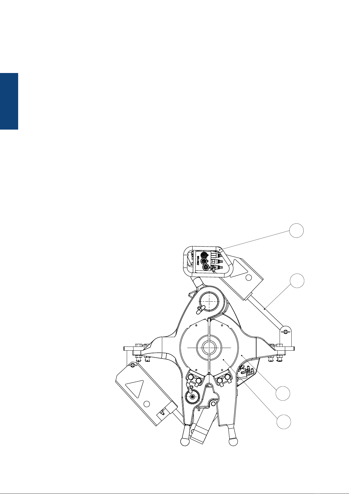
1. DESCRIPTION
Main assembly
The Elevator 613000-Y-H-F
consist of the following main
assemblies:
1. Elevator body with a latch
2. Mechanic Kit
3. Hydraulic Assembly
4. Bushing System
General
The Blohm + Voss VES-CL Elevator is designed with strength and safety factors in accordance with API Section 8C -
Regulations and will be used for handling long, heavy strings drill pipe.
The design of the bushing segments allows the tool to lift tubular, ensuring a safe hold while minimizing the possibility of
damage to the pipe. This model is available for hydraulic power operation.
Intend of use
The elevator is designed to be installed into Elevator links and handle vertical pipes.
WARNING
the lIftING of veRtIcAl pIpes Is to be peRfoRmed cARefully ANd must be moNItoRed. the pIckING up of hoRIzoNtAl oR tIlted pIpes Is dANGeRous ANd
Not peRmItted by the mANufActuReR.
WARNING
Ifthe opeRAtoR coNsIdeRs to use the elevAtoR foR otheR opeRAtIoNs thAN the INteNded use (foR exAmple hANdlING of hoRIzoNtAl pIpes), It Is
mANdAtoRy to mAke AN AddItIoNAl RIsk ANAlysIs.
1
3
2
4

11
DESCRIPTION
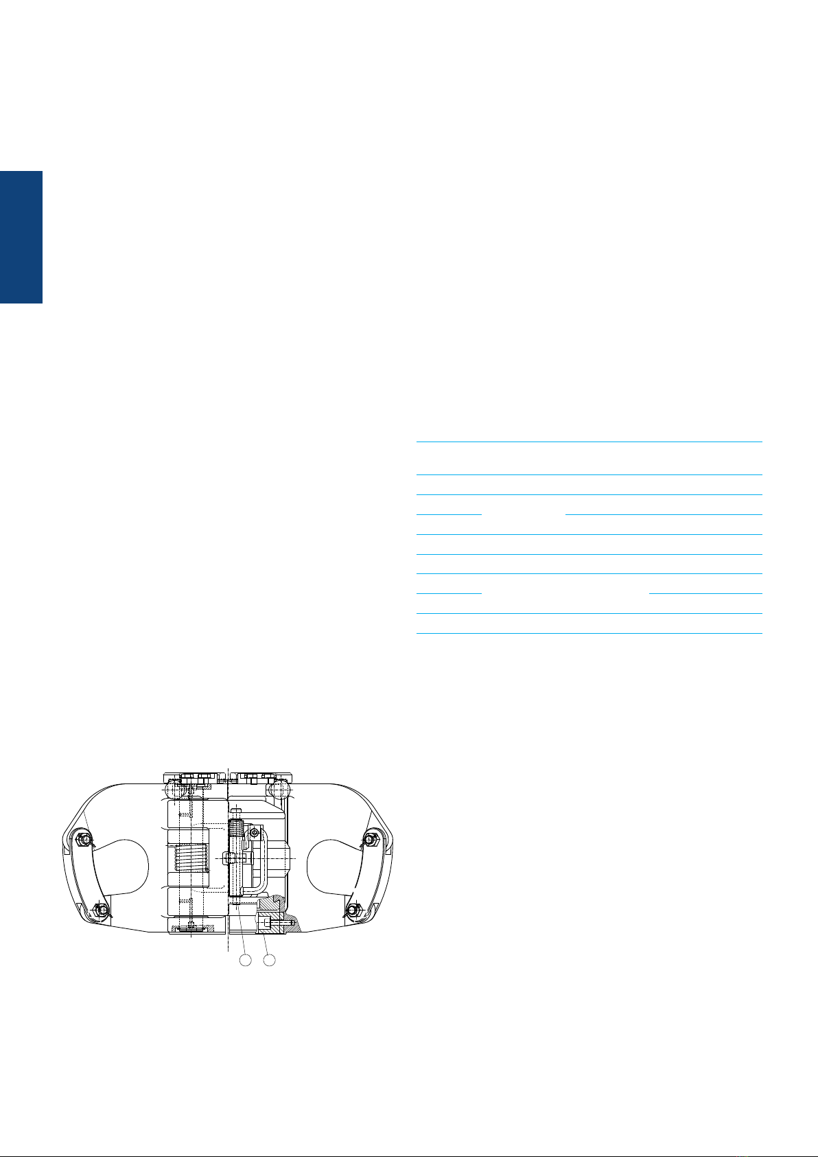
Elevator body and hydraulic closing system
When the elevator is open, the drill pipe can be placed in the elevator.
When the elevator is closed, the elevator sends a hydraulically signal.
The body takes the load through the bushing system and transfer it to the elevator links.
Bushing System
Exchangeable bushings allow to run the elevator for different tubular and sizes, see chapter „Size Components“.
Opening and Closing Mechanics
Body and latch of the elevator are actuated by hydraulic cylinders.
The cylinders are installed in the hydraulic areas of the elevator in a protected way.
Closing signal unit
When the bodies are completely closed and latched, the closing signal in the elevator is actuated.
* If not otherwise stated in the databook
Available Pipe Size Range (Bushing System)
VES-HCL 350
Drill Pipe 2.3/8“- 6.5/8“
Drill Collars 3.1/2“- 6.3/4“
Casing 3.1/2“- 7“
Tubing 2.3/8“- 5.1/2“
VES-HCL 350 Center Latch Elevator
Temperature working range ambient - 20° C to + 60° C*
- 4° F to 140° F*
Load Capacity 350 sh tons
Part number 613000-Y-H-F (with closing signal)
API test load 525 sh tons
Weight 425 kg (937 Lbs)
Size O.D. 2.3/8“-7“
Bushings 613902-BC
Elevator Links 2.1/4” up to 3.1/2” (250t to 500t)
Working pressure Min 130 bar (1,885 Psi),
Maximum allowed pressure 210 bar (3045 Psi)
Required Flow rate Min 6,6 Gpm (25 l/m)
Max 25 Gpm (94 l/m)
Minimum required clearness of hydraulic
fluid NAS 9
Max temp hydraulic fluid + 60° C
+ 140° F
Technical Data

12
DESCRIPTION
Couplings
Screw couplings male and female with connecting thread
NPT – 3/8“ inner thread.
All hydraulic connections have a bushing and a plug.
Safety equipment
Closing signal
When the latch is completely closed, line “C” triggers a
hydraulic pressure signal of 110 to 120 bar as a feedback
signal, indicating elevator closed.
Improper / Unsafe Use
The VES-HCL350 Elevator must only be used for the
designated purpose.
When using the VES-HCL350 Elevator, the load of 350 sh
tons must never be exceeded.
Identification
The identification area clearly identifies the Elevator area
(manufacturer, type, material, part number, serial number,
date of manufacture). It is important to keep this information
ready for the purpose of service and repair work.
Functioning
The HCL-350 elevator is designed in 2 halves of about
the same weight for proper balance and easier opening
and closing. Itis equipped with a latch and a latch lock
combination. When the elevator is open, the pipe will be
placed in the bushings.
The HCL-350 elevatorhas exchangeable bushings, which
allows the elevator to run with different types of pipes and
pipe didameters.
1. Elevator is tilted to the pipe.
2. Elevator will close on close command.
3. Once the elevator is closed, latched and locked, the
driller will get a feedback signal stating this.
4. Now the driller can pick up the pipe.
5. Opening the elevator works vice versa
13
DESCRIPTION
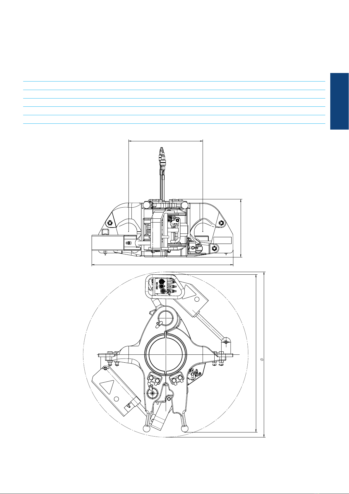
Main Dimensions VES-HCL 350
VES-HCL 350
Length [mm] A 913
Width [mm] B 1017
Height [mm] C 373
[mm] D 480
14
DESCRIPTION
Wear Bushing (optional)
Intend of Use:
B+V Wear Bushing for VES-CL-Bushing Elevators are designed for reducing the Wear of the Elevator and only
designed for being used with B+V VES-CL Bushing Elevators.
Function:
The B+V Wear Bushing for Bushing Elevators have to be choosen according to the size of the Bushing and the bore code
according to the list below.
Before assembling the B+V Wear Bushing to the Elevator check if it is the right one. The P/N on the B+V Wear Bushing has to
be checked with the P/N in this manual.
For assembling the B+V Wear Bushing, you have to make sure that all parts have to be assembled in the correct order and the
screws have to be tightened properly.
21
Item 1:
Elevator Body machined for Wear Bushing
P/N XXXXXX-Y-WB
for example:
P/N 613000-Y-H-F-WB
(VES-CL 350 Elevator for use with Wear Bushing, Wear
Bushing is not included)
Item 2:
Wear Bushing Assembly
P/N 615985-BC
Bore code Pipe Size WB outside
dia. B
Wear bushing
BC 103 2.7/8“ - -
BC 104 3.1/2“ --
BC 105 98,4 615985-105
BC 109 4.1/2“-5“ 131 615985-109
BC 111 5.1/2“ 146 615985-111
BC 113 6.5/8“ 176 615985-113
BC 114 615985-114
BC 115 5.7/8“ 155 615985-115
other sizes on request

15
DESCRIPTION
Hydraulic schematic
R
P
A2B1B2A1
A2
B1
Latch
A1
B2
Elevator
Feedback
1
2
2
1
2
1
2
1
2
2
3
1
2
3
1
MA
MB
C1
AB
C
C2
1

16
DESCRIPTION

17
COMMISIONINGS
COMMISIONING
COMMISSIONING

18
COMMISIONINGS
2. COMMISSIONING
Commissioning VES-HCL 350 Center latch Elevator
Blohm + Voss strongly recommends to accomplish the Elevator commissioning with the
Blohm + Voss Commissioning.
Read manual before first use !
OK oCheck crew is aware of all danger regarding handling the B+V tool.
OK oGo through manual with crew.
Prior to use of the Blohm+Voss Elevator following checks must be carried out :
Scope of supply
OK oCross check all delivered parts
Hydraulic Characteristics
OK oOperating pressure 130 bar / 1885 PSI
OK oVolumetric flow 6.6 Gpm (25 l/m) to 25 Gpm (94 l/m)
OK oHydraulic filter and regulator Filter installed in pressure line
Check and Lubrication
OK oCheck for any damage and repair if needed
OK oCheck elevator is in closed position.
OK oCheck for correct seating of Hinge Pin and Latch Pin.
OK oCheck Hydraulic Supply lines are disconnected.
OK oApply grease to all greasing points until grease is visibly coming out of the
bores.
OK oCheck if elevator is installed as outlined in manual.
OK oConnect feedback lines.
OK oCheck of all bolts, nuts, washers and lock wire are in place.

19
COMMISIONINGS
Function Test
OK oCheck elevator opens by hydraulic pressure.
OK oCheck feedback signal indicates elevator closed and latched.
OK oCheck required bushings are installed before first use
OK oCheck all bushing segments are of same size and serial number elevator
OK oCheck if bushings are fixed correctly
OK oCheck 18° shoulder with gauge P/N 600168 for wear
OK oCheck all safety / lock wire is present.
OK oCheck if feedback valve is present.
OK oCheck elevator closes by hydraulic pressure.
OK oPick up a pipe.
OK oCheck if elevator opens after giving command “open elevator”

20
COMMISIONINGS
This manual suits for next models
1
Table of contents
Other Blohm + Voss Oil Tools Industrial Equipment manuals


Popular Industrial Equipment manuals by other brands

Ebmpapst
Ebmpapst W3G630-GU23-91 operating instructions

System air
System air SAVE-P VTR 150/B installation instructions

Oriental motor
Oriental motor EZ limo EDR36D-K operating manual

Delta OHM
Delta OHM HD2013 operating manual

Gen Set
Gen Set MG 50 S-P owner's manual

Oriental motor
Oriental motor EZS II Series operating manual


