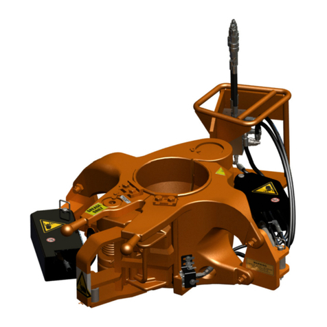
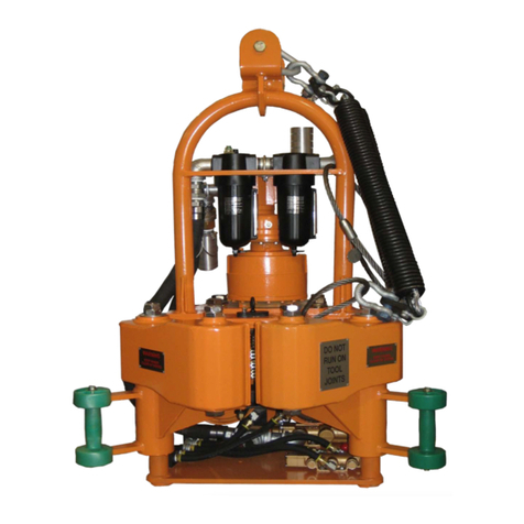
Blohm + Voss Oil Tools FloorHand 9GF-1102 Guide

1
Blohm + Voss Oil Tools, LLC
9GF-1102 Cantilever Style FloorHand with
9FM-2050 Hydraulic Lift
Technical Documentation
Manual Rev 000, October 2011.
To be used with Serial Numbers 200+

2
GENERAL INFORMATION
Warnings and Notes
WARNING: A “WARNING”
INDICATES A DEFINITE
RISK OF EQUIPMENT
DAMAGE OR DANGER TO
PERSONNEL. FAILURE TO
OBSERVE AND FOLLOW
PROPER PROCEDURES
COULD RESULT IN SERIOUS
OR FATAL INJURY TO
PERSONNEL, SIGNIFICANT
PROPERTY LOSS, OR
SIGNIFICANT EQUIPMENT
DAMAGE.
NOTE: A “NOTE” indicates
that additional information is
provided about the current
topics.
Intended use of this
manual
WARNING: THIS TECHNICAL
DOCUMENTATION CONTAINS
INSTRUCTIONS ON SAFETY,
INSTALLATION, OPERATION
AND MAINTENANCE. IT
MUST BE STUDIED BEFORE
WORKING WITH THE TOOL.
This manual is
intended for use by eld
service, engineering,
installation, operation, and
repair personnel. Every
effort has been made to
ensure the accuracy of the
information contained herein.
Blohm + Voss Oil Tools, LLC,
will not be held liable for
errors in this material, or for
consequences arising from
misuse of this material.
Anyone using service
procedures or tools, whether
or not recommended by
Blohm + Voss Oil Tools,
LLC, must be satised that
neither personal safety nor
equipment safety will be
jeopardized.
Intellectual property
All rights retained.
No part of this document
may be reproduced in any
form (print, photocopy,
microlm or any other
procedure) or be processed
using an electronic system
without written approval of
Blohm + Voss Oil Tools, LLC
All information
contained in this manual
is based upon the latest
product information available
at the time of printing.
Dependent on ongoing
technical improvements
(ISO 9001) “Blohm + Voss
Oil Tools, LLC” reserves the
right to change the design
and specications without
announcement.
The values specied in
this manual represent the
nominal values of a unit
produced in series. Slight
deviations in the case of
the individual devices are
possible.
NOTE: In the event of
problems that cannot be
solved with the aid of this
manual, please contact
one of the addresses listed
below.
General remarks
As with all rig
equipment, the FloorHand
must be operated in
accordance with accepted
rig safety practices and
procedures. All operators
should be familiar with all
safety precautions and
recommended installation
and operating procedures,
including the information
provided in this manual and
any other safety publications
by Blohm + Voss Oil Tools,
LLC Listed on the next page
are safety considerations
and warnings found
throughout this manual:
CE Marking
The tool complies with
the Machinery Directive
2006/42/EC and the
Directive 2014/34/EU
“Equipment and protective
systems in potentially
explosive atmospheres”
The marking is as follows:
CE Ex II 2G T5
Patents
The following patent
numbers apply:
U.S. 11/404,317
U.S. 11/890,582
U.S. 11/732,813
Limited Warranty
The warranty provided will
be void if the FloorHand is
either:
1. Repaired or serviced by
a service facility which
was not authorized by
Blohm + Voss Oil Tools,
LLC.
2. Replacement parts not
manufactured by Blohm
+ Voss Oil Tools, LLC are
used.
3. Modications were made
to the FloorHand which
were not approved by
Blohm + Voss Oil Tools,
LLC.
Manufacturer & Agents World Wide
Blohm + Voss Oil Tools
Hermann-Blohm-Straße 2
20457 Hamburg, Germany
Phone: +49(0)40/3119-1826/1162
Fax: +49(0)40/3119-8194
oiltools@blohmvoss.com
www.blohmvoss-oiltools.com
Premier Sea & Land Pte. Ltd.
Shaw Centre
1, Scotts Road #19-12
228208 Singapore
Republic of Singapore
Phone: +65-6734-7177
Fax: +65-6734-9115
enquiries@mtqpremier.com.sg
Blohm + Voss Oil Tools, LLC
7670 Woodway, Suite 266 Houston, Texas
77063
United States of America
Phone: +1-713-952-0266
Fax: +1-713-952-2807
BVOT@blohmvoss.com
www.blohmvoss-oiltools.com

3
Safety issues
WARNING: ONE SHOULD
AVOID CREATING IGNITION
SOURCES, LIKE HEAT, AS A
RESULT OF THE USE OF THE
TOOL WITH OTHER TOOLS
OR EQUIPMENT.
WARNING: THE WARNING
PLATES, SIGNS AND LABELS
MUST BE PRESENT ON THE
TOOL. DO NOT REMOVE
THE LABELS. IF THEY ARE
MISSING, REPLACING IS
MANDATORY.
WARNING: ALL WARNING
PLATES, SIGNS AND
LABELS ATTACHED TO
THE EQUIPMENT MUST BE
OBSERVED.
WARNING: DO NOT USE
THE TOOL FOR ANY OTHER
PURPOSE THAN MAKING UP
AND BRAKING OUT WITHIN
ITS SPECIFICATION.
NOT RE-USE THEM. ALWAYS
REPLACE THEM WITH NEW
SAFETY ELEMENTS.
WARNING: KEEP HANDS
AND ARMS CLEAR OF
ALL MOVING PARTS
WHEN CONNECTING,
DISCONNECTING OR
OPERATING THE UNIT.
WARNING: ALWAYS WEAR
PROTECTIVE GEAR FOR
EYES, HEAD, HANDS AND
FEET.
WARNING: WHEN SERVICING
UNIT, BE SURE ALL POWER
IS OFF AND SUPPLY LINES
ARE DISCONNECTED AND
INTERNAL PRESSURE IS
BLED FROM THE TOOL.
WARNING: LUBRICATE UNIT
ONLY WHEN SUPPLY LINES
ARE DISCONNECTED AND
H.P.U IS OFF AND TAGGED
OUT. VERIFY THAT SYSTEM
PRESSURE IS -0- PSI.
WARNING: ALWAYS USE
LIFTING APPARATUS
(SLINGS, CABLES,
SHACKLES AND THE
LIKE) THAT HAVE BEEN
INSPECTED AND ARE IN
GOOD CONDITION AND ARE
PROPERLY SIZED. ENSURE
THAT ALL RIGGING AND
LIFTING PROCEDURES
ARE IN ACCORDANCE
WITH ACCEPTED
OILFIELD PRACTICES AND
STANDARDS.
WARNING: ALWAYS
CHECK THE UNIT FOR
LOOSE FASTENERS AND
HYDRAULIC CONNECTIONS
AS WELL AS ANY OTHER
DAMAGE PRIOR TO TURNING
ON THE POWER UNIT.
WARNING: FAILURE TO
CONDUCT ROUTINE
MAINTENANCE COULD
RESULT IN EQUIPMENT
DAMAGE OR INJURY TO
PERSONNEL.
WARNING: THE TOOL MUST
ONLY BE SERVICED BY
TRAINED B+V PERSONNEL
OR BY AUTHORIZED
PERSONNEL.
WARNING: WHILE WORKING
WITH THE EQUIPMENT,
WEAR PERSONAL
PROTECTION EQUIPMENT.
WARNING: IF ANY
SAFETY ELEMENTS (LIKE
SAFETY ROPES, WIRE,
SAFETY SHEETS, PLATES
OR WASHERS) WERE
DISASSEMBLED DUE TO
MAINTENANCE WORK, DO
Revision History Table
REV. SECTION SUB-SEC. PARA. CHANGE REQUEST # DATE AUTHORIZED BY
Draft All All All N/A 10/01/10 KJ
0 All All All N/A 03/19/12 KJ

4
TABLE
OF CONTENTS
TABLE OF CONTENTS
DESCRIPTION COMMISSIONING INSTALLATION OPERATIONS SPARE PARTS
MAINTENANCE
& INSPECTION DRAWINGS INDEX
TABLE OF CONTENTS 4
DESCRIPTION 6
General Components 7
Wrenches 7
Spinner 7
Frame 7
Controls 7
Lift Cylinder 8
Specications 9
Hydraulic Requirements 9
Shipping Data (Approximately allowing for crate or pallet) 9
COMMISSIONING 12
FloorHand Commissioning Procedure 14
INSTALLATION 17
Normal Rig Move Removal and Installation 18
Lifting 18
Attaching to the Lift Cylinder 19
Locating the HPU and attaching the Hydraulic Lines 19
Attaching the Hydraulic Lines 20
Make Up Torque Adjustment 21
Rig-Up/ Rig-Down 22
FloorHand Wrench Torque Chart 23
OPERATIONS 24
Controls 25
Making a Connection 27
Breaking a Connection 35
Troubleshooting 41
MAINTENANCE & INSPECTION 50
Grease Quality 51
Lubrication 51
Removal of Die-block 54
Replacement of Tong Dies 54
Replacement of Centering Buttons 55
Replacing Spinner Drive Rollers 56
Frequency 59
Inspection 59

5
TABLE
OF CONTENTS
DESCRIPTIONCOMMISSIONINGINSTALLATIONOPERATIONSSPARE PARTS MAINTENANCE
& INSPECTION
DRAWINGSINDEX
Hydraulic System Inspection 59
Dismantling Inspection 59
Check Category I (Ongoing Observation) 60
Check List Category II (Daily) 60
Check List Category III (Every Year) 61
Check List Category IV (Every 2 years) 61
Inspection Categories acc. to API RP 8B 62
Periodic Inspection 62
Inspection Check Lists 63
SPARE PARTS 64
Recommended Spare Parts for One Year Operation 65
DRAWINGS 66
CANTILEVER STYLE FLOORHAND WITH 9FM-2050 HYDRAULIC CYLINDER 68
CANTILEVER FRAME ASSEMBLY 9FH-10001 69
FLOORHAND COMBINATION MANIFOLD 9FH-01539 72
FLOORHAND RETURN MANIFOLD 9FH-01540 73
SPINNER SUB ASSEMBLY 9FH-10302 74
DOUBLE DRIVE ROLLER ASSEMBLY 9FH-01407 76
IDLER GEAR ASSEMBLY 9FH-01287 77
DRIVE ROLLER GEAR ASSEMBLY 9FH-01408 78
UPPER WRENCH SUB ASSEMBLY ORFS 9FH-10201 79
REMOVABLE SPINNER POST ASSEMBLY 9FH-01520 82
LOWER WRENCH SUB ASSEMBLY ORFS 9FH-10101 83
DIE BLOCK ASSEMBLY 9FH-01060 85
2-7/8 ADAPTER KIT ASSEMBLY 9FH-10703 86
2-7/8 DIE BLOCK ADAPTER ASSEMBLY 9FH-01445 87
WINCH AND MOUNTING ASSEMBLY 9FH-10701 88
SERVICE KIT 9FH-10841 89
LOW RANGE TORQUE CYLINDER CHART 90
FLOORHAND COMPLETE HYDRAULIC SCHEMATIC 91
HYDRAULIC SCHEMATIC 92
INDEX 93
Table of contents
Other Blohm + Voss Oil Tools Industrial Equipment manuals


