Bloomfield 1228 User manual

10 Sunnen Drive
St. Louis, MO 63143
telephone: 314-678-6336
fax: 314-781-2714
www.bloomfieldworldwide.com
2M-Z18491 Rev. a M712 150224
715
OWNERS MANUAL
for
3 GALLON HOT WATER
DISPENSER
1228
Includes:
Installation
Operation
Use & Care
Servicing Instructions
Model 1228

715 p/n 2M-Z18419 1228 Owmers Manual
All equipment manufactured by Bloomeld is warranted against defects in
materials and workmanship for the time periods listed in the chart starting
from the date the equipment is placed into service and is for the benet of
the original purchaser:
THE FOREGOING OBLIGATION IS EXPRESSLY GIVEN IN LIEU OF
ANY OTHER WARRANTIES, EXPRESSED OR IMPLIED, INCLUDING
ANY IMPLIED WARRANTY OF MERCHANTABILITY OR FITNESS
FOR A PARTICULAR PURPOSE, WHICH ARE HEREBY EXCLUDED.
BLOOMFIELD, LLC SHALL NOT BE LIABLE FOR INDIRECT,
INCIDENTAL OR CONSEQUENTIAL DAMAGES OR LOSSES FROM
ANY CAUSE WHATSOEVER.
This warranty is void if it is determined that upon inspection by an
authorized service agency that the equipment has been modied,
misused, misapplied, improperly installed, or damaged in transit or by
re, ood or act of God.
It also does not apply if the serial nameplate has been removed or unauthorized service personnel perform service. The prices
charged by Bloomeld for its products are based upon the limitations in this warranty. Seller’s obligation under this warranty
is limited to the repair of defects without charge by a Bloomeld Authorized Service Agency or one of its sub-agencies. This
service will be provided on customer’s premises for non-portable models. Portable models (a device with a cord and plug or a
dispenser) must be taken or shipped to the closest authorized service agency, transportation charges prepaid, for services.
Agencies are located in principal cities, please visit our website to locate one.
This warranty is valid in the United States and Canada and void elsewhere. Please consult your classied telephone directory
or your food service equipment dealer; or, for information and other details concerning warranty, write to:
Service Parts Department; Bloomeld
10 Sunnen Drive, St. Louis, MO 63143
Phone: (314) 678-6336 : Fax: (314) 781-2714
Technical@ bloomeldworldwide.com / www.bloomeldworldwide.com
BLOOMFIELD SERVICE POLICY AND PROCEDURE GUIDE ADDITIONAL WARRANTY EXCLUSIONS
1. Resetting of safety thermostats, circuit breakers, overload protectors, or fuse replacements.
2. All problems due to operation at voltages other than specied on equipment nameplates - conversion to correct voltage
must be the customer’s responsibility.
3. All problems due to electrical connections not made in accordance with electrical code requirements and wiring diagrams
supplied with the equipment.
4. Replacement of items subject to normal wear, to include such items as knobs and light bulbs. Normal maintenance
functions including adjustment of thermostats, microswitches, and replacement of fuses and indicating lights are not
covered under warranty.
5. All problems due to inadequate water supply, such as uctuating, or high or low water pressure.
6. All problems due to mineral/calcium deposits, or contamination from chlorides/chlorines. De-liming is considered a
preventative maintenance function and is not covered by warranty.
7. Full use, care and manuals may or may not be sent with each unit, only a condensed version. Please visit our web site to
download the full version.
8. Travel mileage is limited to fty (50) miles from an authorized service agency or one of its sub-service agencies.
9. All labor shall be performed during normal working hours. Overtime premium shall be charged to the customer.
10. All genuine Bloomeld replacement parts are warranted for ninety (90) days from date of purchase on non- warranted
equipment. Any use of non-genuine Bloomeld parts completely voids any warranty.
11. Installation, labor and job checkouts are not considered warranty.
12. Charges incurred by delays, waiting time or operating restrictions that hinder the service technicians ability to perform
services are not covered by warranty. This includes institutional and correctional facilities.
SHIPPING DAMAGE CLAIMS PROCEDURE
NOTE: For your protection, please note that equipment in this shipment was carefully inspected and packaged by skilled
personnel before leaving the factory. Upon acceptance of this shipment, the transportation company assumes full responsibility
for its safe delivery.
IF SHIPMENT ARRIVES DAMAGED:
1. VISIBLE LOSS OR DAMAGE: Be certain that any visible loss or damage is noted on the freight bill or express receipt,
and that the note of loss or damage is signed by the delivery person.
2. FILE CLAIM FOR DAMAGE IMMEDIATELY: Regardless of the extent of the damage.
3. CONCEALED LOSS OR DAMAGE: if damage is unnoticed until the merchandise is unpacked, notify the
transportation company or carrier immediately, and le “CONCEALED DAMAGE” claim with them. This must be done
within fteen (15) days from the date the delivery was made to you. Be sure to retain the container for inspection.
Bloomeld cannot assume liability for damage or loss incurred in transit. We will, however, at your request, supply you with the
necessary documents to support your claim.
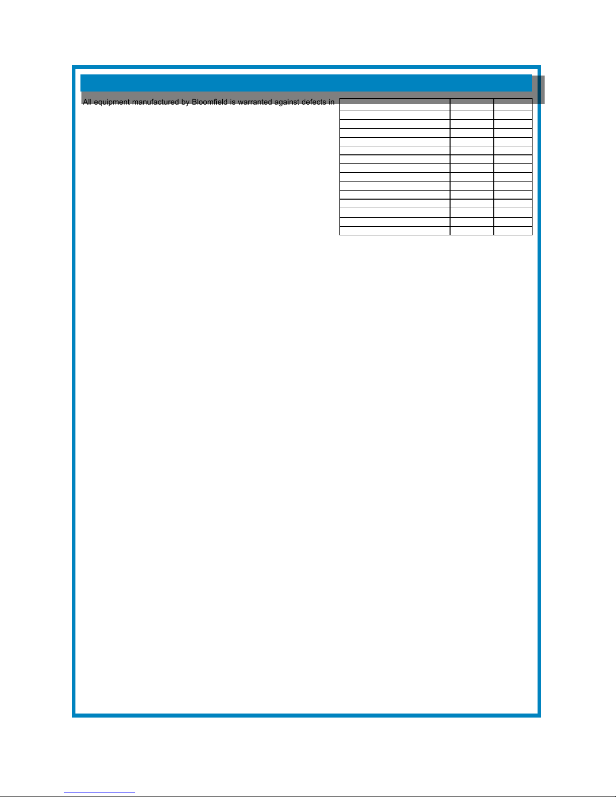
WARRANTY STATEMENT
Equipment Parts Labor
pour over, automatic coffee brewers 2 yrs. 2 yrs.
EBC, EMAX coffee brewers 2 yrs.* 2 yrs.
* EBC, EMAX coffee brewer control 3 yrs. no labor
POD coffee brewers 1 yr. 1 yr.
ECO coffee brewers 1 yr. 1 yr.
coffee warmers 1 yr. 1 yr.
in room brewers 1 yr. 1 yr.
tea brewers 2 yrs. 2 yrs.
tea dispensers 1 yr. 1 yr.
tea dispenser BBTea 1 yr. no labor
hot water machines 2 yrs. 2 yrs.
thermal servers 90 days no labor
airpots 30 days no labor
decanters no warranty no warranty

3
715 p/n 2M-Z18419 1228 Owmers Manual
TABLE OF CONTENTS
SPECIFICATIONS
Thank You for purchasing
thisBloomeld appliance.
Proper installation, professional
operation and consistent
maintenance of this appliance will
ensure that it gives you the very
best performance and a long,
economical service life.
This manual contains the
information needed to properly
install this appliance, and to use,
care for and maintain or repair the
appliance in a manner which will
ensure its optimum performance.
WARRANTY STATEMENT xi
SPECIFICATIONS 1
FEATURES & OPERATING CONTROLS 2
PRECAUTIONS & GENERAL INFORMATION 3
AGENCY LISTING INFORMATION 3
INSTALLATION INSTRUCTIONS 4
OPERATION 6
CLEANING INSTRUCTIONS 7
TROUBLESHOOTING SUGGESTIONS 8
SERVICING INSTRUCTIONS 9
Deliming Instructions 12
EXPLODED VIEW & PARTS LIST 13
WIRING DIAGRAMS 16
APPLICABILITY
This manual applies to the following Bloomeld products:
1228 3-Gallon Deluxe Digital Hot Water Dispenser
Technical Specication
Model Voltage Amps Watts Dimension Shipping
Weight
Power
Cord
Water Inlet
Pressure
Width Depth Height
1228
120V 15 1,800
11.4”
(29 cm)
18.3”
(46.5 cm)
25.78”
(65.5 cm)
28.6 lbs
(13 kg)
5-15P
20 to 90 psi
120C 12 1,440
208V 11.8 2,454 6-20P
240V 13.6 3,264

4
715 p/n 2M-Z18419 1228 Owmers Manual
FEATURES AND OPERATING CONTROLS
IL2819
A Control Panel
B LED Display
CFuncon Buon
DOn / O Buon
E Water Dispensing Tap
F Name Plate
G Filter Cartridge
H Drip Tray & Cover

5
715 p/n 2M-Z18419 1228 Owmers Manual
PRECAUTIONS AND GENERAL INFORMATION
WARNING: ELECTRIC SHOCK HAZARD
All servicing requiring access to non-insulated components must be performed by qualied
service personnel. Do not open any access panels which require the use of tools.
Failure to heed this warning can result in electrical shock.
WARNING: INJURY HAZARD
All installation procedures must be performed by qualied personnel with full knowledge of all
applicable electrical and plumbing codes. Failure could result in property damage and
personal injury.
WARNING: ELECTRIC SHOCK HAZARD
Hot Water Dispenser must be properly grounded to prevent possible shock hazard.
DO NOT assume a plumbing line will provide such a ground. Electrical shock will cause death
or serious Injury.
WARNING: BURN HAZARD
This appliance dispenses very hot liquid. Serious bodily injury from scalding can occur from
contact with dispensed liquids.
This appliance is intended for commercial use only.
This appliance is intended for use to dispense heated
water. No other use is recommended or authorized by the
manufacturer or its agents.
This appliance is intended for use in commercial establishments,
where all operators are familiar with the appliance use,
limitations and associated hazards. Operating instructions and
warnings must be read and understood by all operators and
users.
The following trouble shooting, component views and parts lists
are included for general reference, and are intended for use by
qualied service personnel.
This manual should be considered a permanent part of this
appliance. The manual must remain with the appliance if it is
sold or moved to another location.
CAUTION:
EQUIPMENT DAMAGE
DO NOT plug in or energize this
appliance until all Installation
Instructions are read and followed.
Damage to the dispenser will
occur if these instructions are not
followed.
CAUTION:
BURN HAZARD
Dispensed liquid is VERY HOT
and can cause burns.
CAUTION:
BURN HAZARD
Exposed surfaces of the
appliance may be HOT to the
touch and can cause burns.
AGENCY LISTING INFORMATION

6
715 p/n 2M-Z18419 1228 Owmers Manual
INSTALLATION
READ THIS CAREFULLY BEFORE STARTING THE INSTALLATION
REFER TO EXPLODED VIEWS PAGE 14 FOR COMPONENT
NAMES/NUMBERS.
Unpack the unit. Inspect all components for completeness and
condition. Ensure that all packing materials have been removed
from the unit.
LEVELING THE UNIT
Be sure dispenser is placed on a solid level surface with all four
feet touching the surface.
PLUMBER’S INSTALLATION INSTRUCTIONS
Dispenser should be connected to a POTABLE WATER, COLD
WATER line. Flush water line before connecting to appliance.
DO NOT use a saddle valve with a self-piercing tap for the water
line connection. Such a tap can become restricted by waterline
debris. For systems that must use a saddle tap, shut off the
main water supply and drill a 3/16” (minimum) tap for the saddle
connection, in order to insure an ample water supply. Remember
to ush the line prior to installing the saddle.
The dispenser must be installed on a water line with average
pressure between 20 PSI and 90 PSI. If your water pressure
exceeds 90 PSI at anytime, a pressure regulator must be
installed in the water supply line to limit the pressure to not more
than 90 PSI in order to avoid damage to lines and solenoid.
A water shut-off valve should be installed on the incoming water
line in a convenient location (Use a low restriction type valve,
such as a 1/4-turn ball valve, to avoid loss of water ow thru the
valve.
IMPORTANT:
To enable the installer to make
a quality installation and to
minimize installation time, the
following suggestions and tests
should be done before the
actual unit installation is started:
CAUTION:
EQUIPMENT DAMAGE
DO NOT plug in or energize this
appliance until all Installation
Instructions are read and
followed. Damage to the
dispenser will occur if these
instructions are not followed.
CAUTION:
UNSTABLE
EQUIPMENT HAZARD
It is very important for safety
and for proper operation that
the dispenser is level and
stable when standing in its nal
operating position. Failure to
do so will result in movement of
the dispenser which can cause
personal Injury and/or damage
to appliance.
NOTE: Water supply inlet line
must meet certain minimum
criteria to insure successful
operation of the dispenser.
Bloomeld recommends 1/4”
copper tubing for installation of
less than 12 feet and 3/8” for
more than 12 feet from a 1/2”
water supply line.

7
715 p/n 2M-Z18419 1228 Owmers Manual
INSTALLATION (continued)
NOTE: This equipment must
be installed to comply with
applicable federal, state and
local plumbing codes and
ordinances.
CAUTION:
SHOCK HAZARD
Dispenser must be properly
grounded to prevent possible
shock hazard. DO NOT
assume a plumbing line
will provide such a ground.
Electrical shock will cause death
or serious injury.
IMPORTANT:
Supply power must match
nameplate for voltage and
phase. Connecting to the
wrong voltage will damage the
appliance or result in decreased
performance. Such damage is
not covered by warranty.
IMPORTANT: The ground
prong of the plug is part of a
system designed to protect
you from electrical shock in
the event of internal damage.
Never cut off the ground prong
nor twist a blade to t an
existing receptacle. Contact a
licensed electrician to install the
proper circuit and receptacle.
NSF requires that the unit be able to be moved for cleaning
underneath. A ex line or loops of copper tubing will satisfy this
requirement. See Figure 2 below.
In some areas, local codes require a backow preventer (check
valve) to be installed on the inlet water line. If a backow
preventer is used, you must install a water hammer arrester in the
incoming line, between the backow preventer and the brewer
inlet, as far away from the brewer as space will allow. This will
relieve the excessive back pressures that can cause faucet leaks
and solenoid malfunctions.
ELECTRICIAN’S INSTALLATION INSTRUCTIONS
REFER TO ELECTRICAL SPECIFICATIONS - Page 1
Check the nameplate to determine correct electrical service
required for the dispenser to be installed.
IMPORTANT: Before connecting to electricity, make sure
dispenser is connected to the water supply.
Model 1228 is equipped with a cord and plug. It requires a
115 - 125 volt 20 amp circuit (50/60 Hz, 2 wire plus ground, with
NEMA 5-15R).
CAUTION: EQUIPMENT DAMAGE
DO NOT connect Model 1228 to a circuit with voltage
higher than the voltage it is designed for.
Equipment damage will result.
Such damage is NOT covered by warranty.
IL2351
COPPER LOOPS OR
FLEX LINES
(PROVIDED BY
PLUMBER)
SOLENOID
STRAINER
WASHER
FLOW
WATER
SUPPLY
WATER INLET
FITTING
SHUT-OFF VALVE
(PROVIDED BY
PLUMBER)
Fig. 2 Water Supply Installation
NEMA 6-20P
RECEPTICLE
NEMA 6-20P
PLUG
IL2820

8
715 p/n 2M-Z18419 1228 Owmers Manual
OPERATION
WATER HEATER
Water temperature is sensed by a probe into the water tank.
Temperature is controlled by a electronic control.
The setpoint temperature is adjustable by adjusting the set temperature
in the programming.
Excessive temperature will trip the hi-limit safety switch, disabling the
heating element. The hi-limit will automatically reset when the dispenser
cools.
WATER LEVEL
Water level is controlled by an electronic controller. The water level
probe senses chassis ground through the water. When the water level
is below the probe no ground is sensed. The controller opens the ll
solenoid until the water level makes contact with the probe.
INITIAL START-UP
For initial start-up, or if the dispenser has not been used for an extended
period of time:
• Be sure the water supply is properly connected, and the unit is
plugged into the correct outlet.
• Switch ON the main water supply and turn ON the unit.
• Leave unit for 30 minutes to allow it to ll completely.
• Drain off approxately 1.5 galllons of water to remove any loose
carbon particles from the lter.
DAILY OPERATION
The boiler starts automatically when the water supply is turned on.
During the heating cycle, only small quantities of water are added to
ensure hot water is always available at the tap.
The boiler is designed to be permanently switched on: it is only
necessary to turn it off for de-scaling or maintenance.
Water is drawn off through the tap (E).
STANDBY
If the unit is to be left unused for a long period of time, the element can
be turned OFF by pressing the power button.
CAUTION:
BURN
HAZARD
Dispensed water is
extremely hot. Hot water
will cause
serious skin burns.

9
715 p/n 2M-Z18419 1228 Owmers Manual
Adjustment – Water temperature, screen backlight and
contrast
Turn power off and on again. The FilterFlow screen (B) is displayed on
the control panel (A).
Press and hold the power button (D) until the software version is
displayed. Press the function button Fn (C) and the temperature will be
displayed.
Press the power button to cycle through the values 158°-204°F
(70°-96°C). Press the Fn button to select the required value.
The backlight adjustment screen is displayed next. Press the power
button to cycle through values 1-25. Press the Fn button to select the
required value.
The contrast adjustment screen is displayed next. Press the power
button to cycle through values 35-60. Press the Fn button to select the
required value.
Press the power button to exit.
OPERATION continued
A Control Panel
B LED Display
CFuncon Buon
DOn / O Buon
E Water Dispensing Tap
F Name Plate
G Filter Cartridge
H Drip Tray & Cover
IL2819

10
715 p/n 2M-Z18419 1228 Owmers Manual
FILTER REPLACEMENT
The lter display shows the estimated life remaining in the lter cartridge.
A reminder message is displayed when the lter needs changing The
unit can be used without a lter, but scale will build up quickly and water
taste may be affected.
To replace the lter:
Twist the base of the lter (G) 90 degrees to the left and lower the
cartridge out of the appliance. It will contain a small amount of water.
Remove the black cap and place it on the new lter.
Re- insert the lter into the recess and lock in place by twisting to the
right.
Press and hold the Fn button for 5 seconds to reset the lter life.
Drain off approximately 1.5 gallons (5 litres) of water to remove any loose
carbon particles from the lter.
MAINTENANCE
CHANGE
FILTER
STANDBY
FILTER READY
CLEAR
IL2822
IMPORTANT:
Other than replacing
the lter, all servicing,
maintenance and component
replacement on these
appliances should be carried
out by one of our authorized
service agents.

11
715 p/n 2M-Z18419 1228 Owmers Manual
CLEANING INSTRUCTIONS
PROCEDURE: Clean Hot Water Dispenser
FREQUENCY: Daily
TOOLS: Mild Detergent, Clean Soft Cloth or Sponge
Bristle Brush
1. Wipe exterior of dispenser with a soft clean cloth or sponge
moistened with mild detergent and clean water. Rinse by
wiping with a soft clean cloth or sponge moistened clean
water.
2. Wipe faucet nozzle to remove any mineral deposits. A
bristlebrush may be used to remove stubborn mineral
build-up.
Procedure is complete
CAUTION:
BURN HAZARD
Dispensed water is extremely
hot. Hot water will cause
serious skin burns.
CAUTION:
SHOCK HAZARD
Do not submerge or immerse
dispenser in water.
IMPORTANT:
DO NOT use steel wool, sharp
objects, or caustic, abrasive or
chlorinated cleansers to clean
the dispenser’s stainless steel
surfaces.

12
715 p/n 2M-Z18419 1228 Owmers Manual
CLEANING INSTRUCTIONS: DESCALING
PROCEDURE: Descaling Water Tank on the Unit
PRECAUTIONS: Disconnect dispenser from electric power.
Allow dispenser to cool below 140°F.
FREQUENCY: Depends on the hardness of your water, and
timely lter replacement.
TOOLS: 3mm Allen Wrench, Descaling agent
1. Wear protective clothing
2. Turn OFF the power by unplugging the unit and let the water
cool to approximately 140°F to avoid injury.
3. Using a 3mm Allen wrench, remove the screw on the top of
the boiler.
4. Remove the insulation on top of the tank, then unscrew and
remove the tank lid.
5. Add the descaling agent a little at a time as some types can
cause hot water to splash.
6. Replace the tank lid and outer lid. Place an “OUT OF USE”
sign to prevent use during descaling.
7. Plug in the unit and allow it to heat and run normally for
approximately 30 minutes.
8. Unplug the unit and allow the water to cool.
9. Remove the outer and tank lids again and inspect the tank
and level sensor housings for scale deposits. If necessary
repeat the descaling process.
10. Drain and ush all descaling agent from the tank and
complete as follows
I. Remove the two (2) screws behind the drip tray that
secures the lower front panel
II. Connect a hose from the overow pipe to a bucket and
turn the service valve to drain the remainder of the water
from the tank
III. Flush out the tank with clean water
IV. When empty shut the valve and replace the cover.
11. Replace the tank lid, ensuring that the gasket is sealing the
top of the tank correctly.
12. Fit the outer lid and plug the unit into the wall outlet and turn
ON the unit.
Procedure is complete
CAUTION:
CHEMICAL BURN
HAZARD
Deliming chemicals may be
caustic. Wear appropriate
protective gloves and goggles
during this procedure. Never
siphon deliming chemicals or
solutions by mouth.
This operation should only be
performed by qualied and
experienced service personnel.
IMPORTANT: DO NOT spill,
splash or pour water or deliming
solution into or over any internal
component other than the inside
of the water tank.
IMPORTANT: DO NOT allow
any internal components to
come into contact with the
deliming solution. Take care to
keep all internal components
dry.
NOTE: Repeat these steps as
necessary to remove all scale
and lime build-up.
NOTE: Normally, silicone
hoses do not need to be
delimed. Should deliming hoses
become necessary, Bloomeld
recommends replacing the
hoses

13
715 p/n 2M-Z18419 1228 Owmers Manual
TROUBLESHOOTING
Message Displayed Possible Cause Corrective Action
Descale Scale on level sensors Descale
Boiler Overlling Check Water Inlet Valve
No Water
Water Turned Off Check water supply and drain valve
Inlet hose bent or blocked
Water pressure too high or low Call service if fault persists
Drain valve open
Not heating
Boil-dry / Overheat Protector tripped Check connections
Temperature sensor fault
Element failed
Call service if fault persistsPCB fault
Faulty / loose connection
Overtemp
Temperature set too high Reduce temperature setting and try again
Temperature sensor fault
Boiler not lling
Call service if fault persistsExcessive scale in tank
PCB fault
Thermistor Temperture sensor fault Call Service
The control panel displays messages and information that can help with fault diagnosis.
Before calling for service, drain off a quart of water, clear the fault code by pressing the
Fn button and turn the unit OFF and ON again at the main suppy. If the fault persist call
service for advice.

14
715 p/n 2M-Z18419 1228 Owmers Manual
EXPLODED VIEW & PARTS LIST
SK2777, Rev. - 5/07/14
Model: 1228
Hot Water Dispenser
1
2
3
4
5
7
10
20
22
23 24
28
29
30 31
34
37
35
36
25
26
27
32
33
21
13
14
15
16
17
11
12
18
19
8 9
6

15
715 p/n 2M-Z18419 1228 Owmers Manual
EXPLODED VIEW & PARTS LIST (continued)
Model 1228, HOT WATER DISPENSER
Fig No. Part No. Qty Description Application
1 TOP PANEL
2 TANK LID
3 WS-Z18536 2 LID GASKET
4WS-Z19913 ELEMENT 120V 1800W 120V
WS-Z18537 ELEMENT 3KW 208/240V 208/240V
5 WS-Z18538 TANK HIGH LIMIT 120°C
6 CLAMP, HIGH LIMIT
7 1/4” / 3/8” ELBOW
8 WS-Z18539 DRAIN HIGH LIMIT 95°C
9 FLATTENED PIPE
10 WS-Z18540 DRAIN VALVE
11 3/8” BARB
12 3/8” T-PIECE
13 DRIP TRAY
14 WS-Z18541 DRIP TRAY PLATE
15 FOOT RIGHT HAND SIDE
16 FOOT LEFT HAND SIDE
17 LOWER FRONT
18 WS-Z19915 SOLENOID VALVE 120V
WS-Z18542 SOLENOID VALVE 208/240V
19 CORD STRAIN RELIEF
20 3/4” BSF, 1/4” TUBE ADAPTER
21 WS-Z18543 TERMINAL BLOCK
22 WS-Z18544 FILTER
23 WS-Z18545 BLOOMFIELD OVERLAY
24 FASCIA
25 FRONT PANEL LOWER TRIM
26 UPPER FRONT
27 WS-Z18546 FAUCET ASSEMBLY
28 WS-Z18547 PCB SPACER
29 WS-Z19914 CONTROL BOARD 120V
WS-Z18548 208/240V
30 WS-Z18549 WASHER, FAUCET
31 WS-Z18550 NUT, FAUCET
32 1/4” ELBOW
33 WS-Z18551 FILTER HEAD
34 WS-Z18552 THERMISTOR
35 3 LEVEL SENSOR INSULATOR
36 WS-Z18553 EB LOWER LEVEL SENSOR
37 WS-Z18554 2 EB UPPER LEVEL SENSOR

WIRING DIAGRAM
16
3-GALLON MODELS 1228
CABLES
N°. Code. Length. Term. Boot.
1 CA168 550 P - P
2 CA168 600 P - P B - B
3 CA168 320 P - P B - B
4 CA168 120 P - P B - B
5 CA20 550 P - P B - -
6 CA169 160 P - P
7 CA169 550 P - P
8 CA169 240 P - P B - -
9 CA170 270 P - TE73
10 CA170 550 P - P
11 CA170 820 P - P
12 CA170 120 - - TE73
1
2
3
4
5
6
7
8
9
10
BB
11
12
PR83
low high
N L in
E
Solonoid
out
Sensors In Thermistor
L out
To control
panel
over
712 p/n 2M-76580 1222_1225_1226 Owmers Manual
Table of contents
Other Bloomfield Dispenser manuals
Popular Dispenser manuals by other brands

MARMON
MARMON Prince Castle Silver King SKMCD1P/C1 Operation manual

Fast Mover
Fast Mover FMT4400 Product instruction manual

Hewi
Hewi 950 Installation and operating instructions

Silver King
Silver King Majestic SK10MAJ Technical manual and replacement parts list

Patron
Patron APOLLO DISPENSER user manual

Kassel Sanitar
Kassel Sanitar KSL00930 Operation and installation guide