Blu Studio J1 User manual

No.20160406
Studio J1 Service Manual

Contents
Chart 1 Product introduction · · · · · · · · · · · · · · · · · · · · · · · · · · · · · · · · · · · · · · ·3--4
1.1 Product view
1.2 Product Feature
Chart 2 Software update procedure · · · · · · · · · · · · · · · · · · · · · · · · · · · · · · · · · · · · 5-9
2.1 Preparation
2.2 Upgrade procedure
Chart 3 Explode view and Part list · · · · · · · · · · · · · · · · · · · · · · · · · · · · · · · · · · 10-11
3.1 Explode view
3.2 Part list
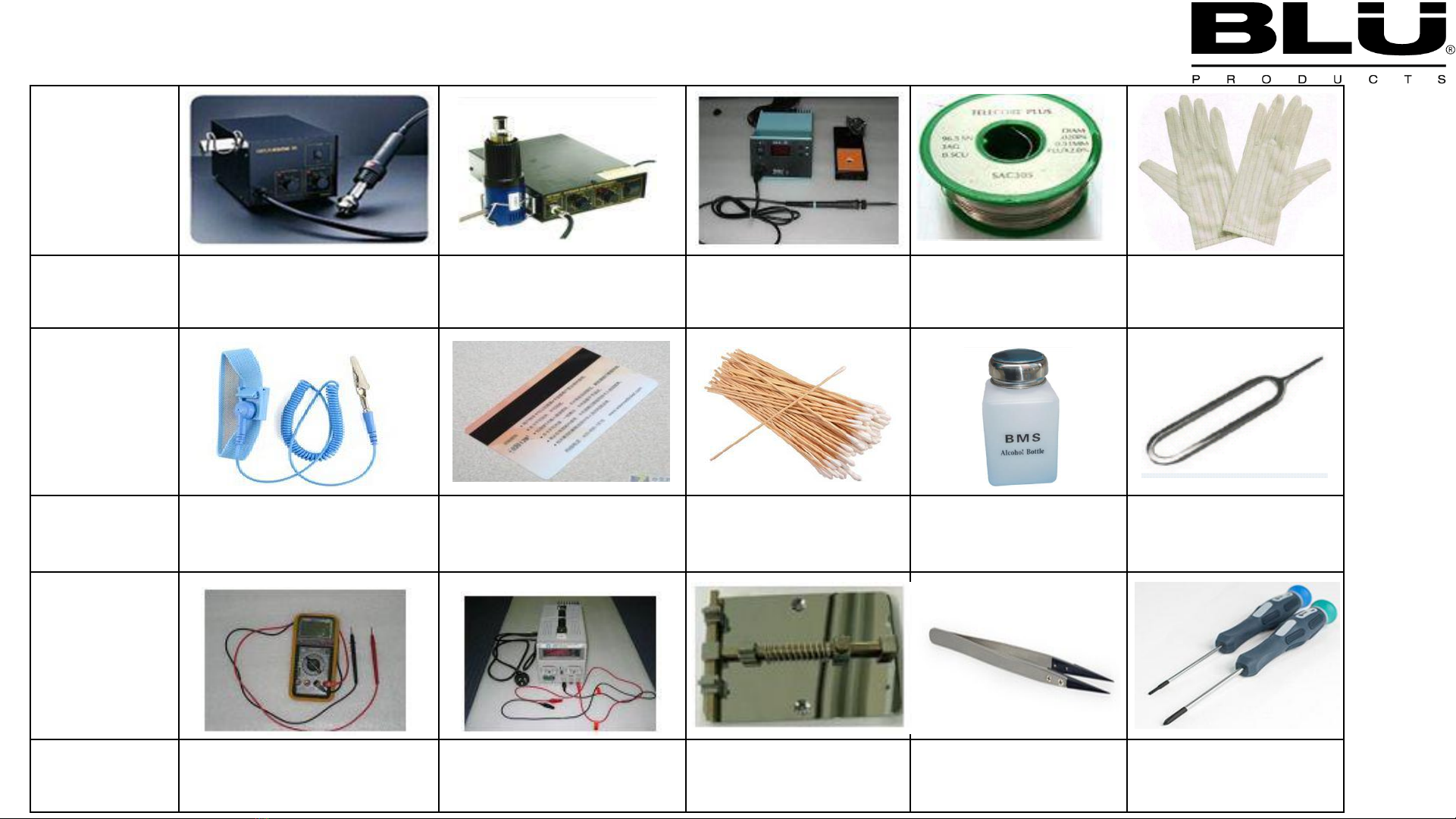
Chart 4 Repair tool · · · · · · · · · · · · · · · · · · · · · · · · · · · · · · · · · · · · · · · · · · · · ·· · · · 12
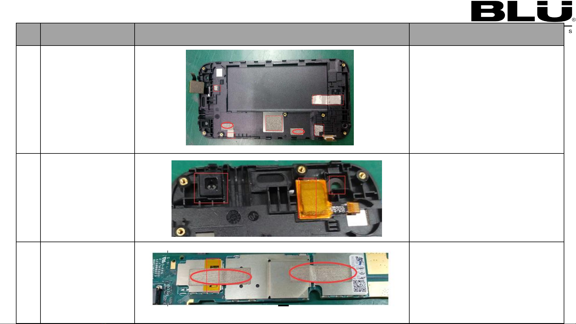
Chart 5 Disassembling procedure and Assembling procedure · · · · · · · · · · · · · · · ·13-22
5.1 Disassembling procedure
5.2 Disassemble loss material
5.3 Assembling procedure
Chart 6 Soldering components for L2 repair · · · · · · · · · · · · · · · · · · ·· · · · ·· · · 23-25
6.1 Component layout
6.2 Partlist
Chart 7 Mobile fault analysis for L2 · · · · · · · · · · · · · · · · · · · · · · · · · · · · · · · · 26-31
Chart 8 Main board · · · · · · · · · · · · · · · · · · · · · · · · · · · · · · · · · · · · · · · · · · · · · · · 32-34
Chart 9 Mobile working principle and Fault analysis · · · · · · · · · · · · · · · · ·· · · 35-45
9.1 Mobile work principle
9.2 Mobile fault analysis
L1
L2
L3
&
L4

Chart 1.Product introduction
This manual provides the technical information to support the service activity of this products
This document contains highly confidential information, so any or all of this document should not be revealed to
any third party.
1.1 Product view

1.2 Product Feature
Phone size
121.5*62.5*10.3mm
CPU
MT6570T/WAZA
Main CPU frequency
1.3GHz Dual
core
Memory type
EMMC+LPDDR3
ROM
8GB
RAM
4Gb
OS
Android
6.0
Display
size
3.97
Material
TN
resolution
WVGA
Front Camera
0.3M
Primary Camera
2.0M
SIM
Card 1/2 System
WCDMA/GSM/GPRS/EDGE
GPS
Yes
Blue
tooth
Yes
Wifi
Yes
FM
Yes
Battery
1350mAh
USB
5pin
micro USB, USB 2.0

Chart 3 Explode view and Part list
3.1 Explode view

3.2 Part list
NO.
Name
QTY
1
A
Cover ASSY
1
2
B
-Cover ASSY /
1
3
C
-Cover ASSY /
1
4
Front
camera
M4610000505LA
1
5
Receiver
M5010000118LA
1
6
Battery
M2330000596LA
1
7
Motor
M4810000096LA
1
8
Main PCBA
M6810501827LA
1
9
2M_Camera
M4620000190LA
1
10
speaker
M4910000186LA
1
11
12

Chart 4 Repair tool
Picture
Name
Hot Air
Gun
Hot Air Gun
Soldering
Iron
Tin
Solder Wire
ESD Glove
Picture
Name
ESD Wrist
Strap
Plastic
Opening
Card
Cotton Swabs
Alcohol
Card inject tool
Picture
Name
Multimeter
DC Power
supply
Soldering
station
Tweezers
Screw
driver

Chart 5 Disassembling procedure and Assembling procedure
NO.
Operation
name
Picture
Operation
and note
1
Remove
C cover
1.Using your fingernail insert into gap
between phone and C cover ,and
sliding along the around of phone to
release hook, then C
-cover will be
removed.
2
Remove Battery
1:Remove
battery with tweezers.
3
Remove battery and
Remove 5pcs
screws
1.Remove
5pcs screws with screw
drivers.
5.1 Disassembling procedure

NO.
Operation
name
Picture
Operation
and note
4
Remove
B cover
1.Using your fingernail insert into
gap between A cover and B
cover ,and sliding along the
around of A cover to release hook,
then B
-cover will be removed.
5
Remove
Main
PCBA_1
1:Remove 2 PCS screws
2:Remove side key reinforcement plate
3:Disconnect the TP connector
4:Remove Receiver
with tweezers
5:Remove Moto
with tweezers
6:Remove
main camera with tweezers
6
Remove
Main
PCBA_2
1:Remove 1 PCS screws
2:Disconnect the LCD
connector
3:Remove Receiver
with tweezers

NO.
Operation
name
Picture
Operation
and note
7
Remove
Speaker
Conductive Fabric,
Support Foam ,
Insulation
Mylar
1:Remove TP_IC
Conductive
Fabric with tweezers
2:Remove Speaker
Conductive
Fabric with tweezers
3:Remove 2pcs
Conductive Fabric
with tweezers
4:Remove 4PCS Conductive Foam
with tweezers
8
Remove
TP-IC
Conductive Fabric
1:Remove TP
-
IC Conductive Fabric with
tweezers
2:Remove Front Camera Foam with
tweezers
2:Remove Front Camera flash seal
rubber with tweezers
9
Remove PCBA
Conductive fabric,
Insulation
Mylar
1
:Remove the 2PCS
Conductive Fabric
and
Insulation Mylar
from the PCBA Board
with tweezers

NO.
Operation
name
Picture
Operation
and note
10
Remove back
camera lens
1
:Remove the lens from the rear shell
by hand
11
X3512_disassembling
procedure have been
completed
X3512_disassembling procedure
have been completed

5.2 Disassemble loss material
NO.
Name
QTY
1
FRONT_CAMERA_FOAM
M6320000323LA
1
2
X3512_TPIC_CONDUCTION_FOAM
M6320000336LA
1
3
X3512_PCB_CONDUCTION_FOAM_1
M6320000338LA
2
4
X3512_PCB_CONDUCTION_FOAM_2
M6320000339LA
1
5
X3512_TPIC_CONDUCTION_FABRIC
M6360000352LA
1
6
X3512_SPK_CONDUCTION_FABRIC
M6360000353LA
3
7
X3512_TPIC_INSULATION_MYLAR
M6340000616LA
1
8
X3512_SHIELD_INSULATION_MYLAR
M6340000626LA
1
9
X3512_SIDEKEY_CONDUCTION_FABR
IC
M6360000371LA
1
10
X3512_PCB_CONDUCTION_FOAM_3
M6320000351LA
1
11

NO.
Operation name
Picture
Operation and note
1
Assemble
TP&LCD on A
shell
Insert the TP FPC into the A shell
2. Insert the LCD FPC into the A shell
3. complete as left second picture;
2
Assemble TP_IC
Conductive Fabric
and
Front Camera
Foam
1
:Assemble front camera seal Foam into
the A shell
2
:
Assemble TP_IC conductive Fabric into
the A shell
3
:Assemble TP_IC Insulation Mylar
into the A shell
3
Assemble PCBA
Conductive fabric
and
Insulation
Mylar
1
:Assemble 2pcs Conductive fabric into
the PCBA
2
:Assemble Insulation Mylar
into the PCBA
5.3 Assembling procedure

NO.
Operation name
Picture
Operation and note
4
Assemble
Conductive
Fabric, Conductive Foam,
1
:Assemble Speaker side key conductive Fabric
into the A
Shell (2PCS)
2
:Assemble LCD Conductive foam 1 into the
PCBA(2
PCS)
3
:Assemble LCD Conductive foam 2 into the
PCBA(1PCS)
4
:Assemble LCD Conductive foam 3 into the
PCBA(1PCS)
5
Assemble
Side key
component
,Moto,
speaker
,receiver front
camera main camera
1
:Assemble main camera into the PCBA
2
:Assemble Receiver into the PCBA
3
:Assemble Moto and speaker,side key
FPC into the PCBA
6
Assemble PCBA into A
shell_1
1
:Assemble front camera into the A shell
2
:Assemble Receiver into the A shell
3
:Assemble moto and speaker into the A
shell
4
:
Assemble 3 pcs screws buckle board on A
shell

NO.
Operation name
Picture
Operation and note
7
Assemble PCBA
into A shell_
1
:Assemble Put TP_IC FPC in PCBA
2
:Assemble LCD_FPC into locker
mechanism completely, as left picture
shown
8
Assemble
BT_WIFI_ GPS
antenna
,main
antenna
1
:Assemble BT_WIFI_GPS antenna,
main antenna into the B shell
2
:Fixed column
9
Assemble B shell
component
1:Assemble B shell
component
2
:1.Fist assemble 5 screws at marked position;

NO.
Operation name
Picture
Operation and note
10
Assemble
SIM1
CARD SIM2
CARD
T CARD
1
:Assemble SIM1 CARD SIM2 CARD
T CARD
11
Assemble Battery
1
:Assemble Battery into the A shell
12
Assemble
back
camera lens
1:Assemble back camera lens

NO.
Operation name
Picture
Operation and note
13
Assemble
C shell
component
1
:Assemble C shell componen
14
Assemble
completely
Assemble completely
15

Chart 6 Soldering components for L2 repair
Main PWB-Top
6.1 Component layout

Chart 6 Soldering components for L2 repair
6.1 Component layout
Main PWB-Bottom

NO.
Name
Location
QTY
1
Touch Shrapnel for BT/WLAN/GPS
A1200 A1201
A1202 A1203
A1204
M5311000122LA
5
2
Earphone socket
J0801
M4390310138LA
1
3
Micro SIM card Connector
J1201 J1203
M4211000198LA
2
4
TF Card connector
J1202
M4212000072LA
1
5
Main camera connector
(BTB_Connector )
J1001
M4313010047LA
1
6
LCD connector and TP connector
J0901
M4313010047LA
1
7
Battery connector
J0501
M4311100544LA
1
8
USB_Connector
J1204
M4315010079LA
1
9
CTP Connector
J0900
M4311100406LA
1
10
Motor
M4810000096LA
1
11
MIC
u0701
M4710000089LA
1
12
Speaker
M4910000186LA
1
6.2 Part list
Table of contents
Other Blu Telephone manuals