Blue Giant STRONGARM RVR303 User manual

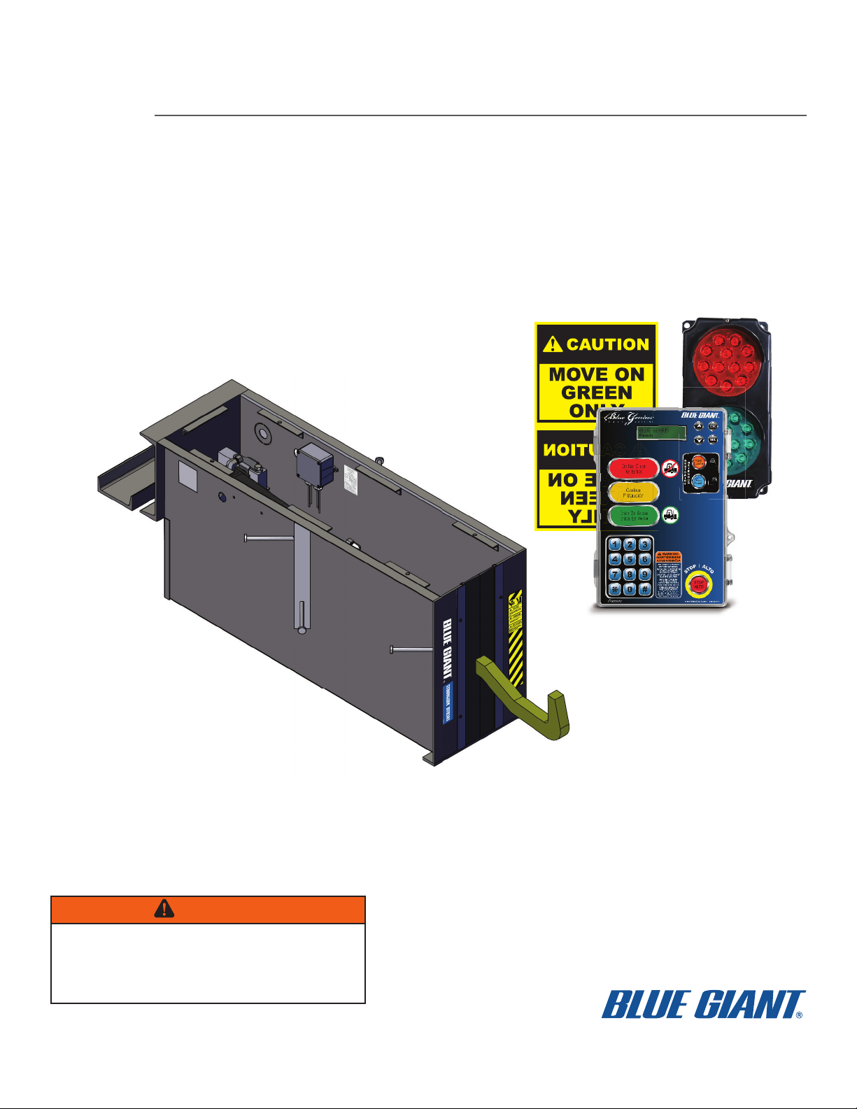
ACTUAL PRODUCT MAY NOT APPEAR EXACTLY AS SHOWN
STARTING FROM JULY 19, 2021 / SERIAL # 0. ISSUE DATE: OCTOBER 26, 2021 REV. 1.0 (PART # 038-953EI)
STRONGARM™ RVR303 VEHICLE RESTRAINT
WITH BLUE GENIUS™ TOUCH CONTROL
INSTALLATION & TECHNICAL MANUAL
WARNING
Do not operate or service this product unless you have
read and fully understand the entire contents of this
manual. Failure to do so may result in property damage,
bodily injury, or death.


STRONGARM™ RVR303 VEHICLE RESTRAINT — INSTALLATION & TECHNICAL MANUAL
3ISSUE DATE: OCTOBER 26, 2021 REV. 1.0 (PART # 038-953EI)
Table of Contents
Table of Contents
1.0 GENERAL SITE CHECKLIST FOR VEHICLE RESTRAINT 5
2.0 INTRODUCTION 6
2.0 INTRODUCTION 6
2.1 WARRANTY INFORMATION 6
2.2 EXCLUSION OF LIABILITY 7
2.3 MANUFACTURER’S NOTE 7
2.4 INSTALLER’S GUIDELINES 7
3.0 SAFETY MESSAGE COLOR IDENTIFICATION 8
3.1 OPERATIONAL SAFETY WARNINGS 8
4.0 LOCKOUT / TAGOUT PROCEDURE AND RULES 10
4.1 ELECTROSTATIC SENSITIVE DEVICE PROTECTION POLICY 11
5.0 INSTALLATION LAYOUT 12
6.0 TOOLS REQUIRED FOR INSTALLATION 16
6.1 RECOMMENDED EQUIPMENT FOR RIGGING OR HOISTING 18
7.0 GENERAL DESCRIPTION 19
8.0 EQUIPMENT COMPONENT ILLUSTRATIONS 20
8.1 COMPONENTS AS SHIPPED CHECKLIST 20
9.0 INSTALLATION GUIDELINES 22
9.1 RESTRAINT INSTALLATION 22
9.2 HOIST RESTRAINT WELDMENT BODY 22
9.3 LEVELING AND SHIM PLACEMENT 22
9.4 CONCRETE FORMS AND BRACING FOR THE RESTRAINT 23
9.5 HOIST CYLINDER ASSEMBLIES (OPTIONAL) 23
10.0 CONTROL STATION INSTALLATION 26
10.1 POWERPACK HARDWARE INSTALLATION 26
10.2 ELECTRICAL CONDUIT INSTALLATION 28
10.3 REMOTE I/O JUNCTION INSTALLATION 29
10.4 POWERPACK ELECTRICAL INSTALLATION 30
10.5 POWERPACK MOTOR WIRING 31
10.6 HYDRAULIC AIR BLEEDING 31
10.7 OIL TYPES 31
10.7 OIL TYPES 31
10.8 INSTALLING THE EXTERIOR DRIVER TRAFFIC LIGHT 32
10.9 INSTALLING THE EXTERIOR DRIVER WARNING SIGN 33
10.10 LIP GUIDE FOR AFTERMARKET (LEGACY) DOCKS 34
10.11 SENSOR RANGE ADJUSTMENT 35
11.0 ELECTRICAL WIRING INSTALLATION 36
11.1 BLUE GENIUS™ CONTROL STATION WIRING LAYOUT 37
11. 2 W IR ING DI AGR A MS 38
11.2 WIRING DIAGRAMS 38
11.3 BLUE GENIUS CONTROL STATION WIRING LAYOUT 38
11.4 WIRING DIAGRAM—115V SINGLE PHASE 38
11.5 WIRING DIAGRAM—208-575V THREE PHASE 39
12.0 PRE-COMMISSIONING INSPECTION CHECKLIST 40
12.1 COMMISSIONING AND START-UP PROCEDURES 41
12.2 BLUE GENIUS™ V2 MENU ACCESS 41
12.3 BLUE GENIUS™ V2 LEARN PROCEDURE 41
12.4 BLUE GENIUS™ V2 TESTING 42
12.5 POWERPACK OIL TYPES 42

STRONGARM™ RVR303 VEHICLE RESTRAINT — INSTALLATION & TECHNICAL MANUAL
4 ISSUE DATE: OCTOBER 26, 2021 REV. 1.0 (PART # 038-953EI)
13.0 TROUBLESHOOTING 43
13.1 VEHICLE RESTRAINT TROUBLESHOOTING 43
13.2 BLUE GENIUS™ LCD MESSAGES 43

1.0
1.0
GENERAL SITE CHECKLIST FOR VEHICLE RESTRAINT
Use this chart to prepare the site for installation.
Yes No Comments
1Review site conditions. Have you completed and reviewed
site survey report? FF
2Is there enough room to mount the RVR303 under the dock?
i.e. dock wall face. FF
3Is the electrical power present to hook up to?
i.e. on inside wall near control install location FF
4Was the conduit(s) installed and properly
positioned? FF
5Did you check to see if the proper voltage is
supplied? FF
6
When un-packing, were all the parts included?
See “8.1 COMPONENTS AS SHIPPED CHECKLIST” on
page 20.
FF
7
Do you have all the tools needed to complete the job? This
includes ladder(s), safety equipment and personal safety
devices. See “6.0 TOOLS REQUIRED FOR INSTALLATION”
on page 16.
FF
8
Do you have all the anchors for the exterior driver traffic
light, warning sign and control box?
Supplied by: You, contractor, installer
FF
9Have you read this installation manual and fully understood
it? FF
10
Do you have the Blue Giant technical support number?
1.800.872.2583. Before calling, make sure to have serial #
of equipment.
FF
11
Do you know what ESD "Electrostatic Sensitive
Device" is and how to handle? See “4.1 ELECTROSTATIC
SENSITIVE DEVICE PROTECTION POLICY” on page 11.
FF
STRONGARM™ RVR303 VEHICLE RESTRAINT — INSTALLATION & TECHNICAL MANUAL
5ISSUE DATE: OCTOBER 26, 2021 REV. 1.0 (PART # 038-953EI)

2.0
2.0
INTRODUCTION
INTRODUCTION
The following is a quick reference to important procedures that must be followed while using the Vehicle Restraint Equipment. It is not
intended to cover, or suggest that it does cover, all procedures necessary to ensure safe operation. All owners and operators should
be aware of and abide by all workplace safety regulations applicable to the inspection and operation of the restraint. These laws and
regulations include but are not limited to:
• The Occupational Safety and Health Act
• Canada Occupational Health and Safety Regulations
• Occupational Safety and Health Acts for Individual States (USA), Provinces, or Territories
• ANSI standard MH30.3-2015
For additional information on these regulations as well as industry standards that may apply to this product, please contact:
American National Standards Institute (ANSI)
1430 Broadway
New York, NY 10018
Telephone: 212.642.4900
www.ansi.org
Also a member of:
Loading Dock Equipment Manufacturers
A Product Section of Material Handling Industry of America
A Division of Material Handling Industry
8720 Red Oak Blvd, Suite 201
Charlotte, NC, 28217-3992
Telephone: 704.676.1190
www.mhi.org/lodem
2.1
2.1
WARRANTY INFORMATION
Thank you for purchasing Blue Giant products. We appreciate your business, and are confident that our product will serve you for many
years to come. In the event that you experience a problem with our product, our Customer Support Team is here to support the
Blue Giant Product(s) that you have purchased.
To validate warranty on recently purchased equipment, please complete and submit your information with our on-line
Warranty Registration at www.BlueGiant.com.
For more information about Blue Giant Warranty Support, please contact your Blue Giant Dealer. You may also visit www.BlueGiant.com or
phone 1.800.872.2583.
NOTE: All products must be registered to qualify for warranty.
DEALER INFORMATION
Name:
Contact:
Telephone:
STRONGARM™ RVR303 VEHICLE RESTRAINT — INSTALLATION & TECHNICAL MANUAL
6 ISSUE DATE: OCTOBER 26, 2021 REV. 1.0 (PART # 038-953EI)

2.2
2.2
EXCLUSION OF LIABILITY
To the maximum extent permitted by applicable law, the manufacturer assumes no liability for damage or injury to persons or property
that occur as a result of use of the Vehicle Restraint Equipment. Furthermore, to the maximum extent permitted by applicable law, the
manufacturer does not assume any liability for lost profits, operating downtimes, consequential, indirect, incidental, special, exemplary,
punitive or enhanced damages, or similar losses, whether incurred by owner, authorized users and, other third parties. By use of the Vehicle
Restraint Equipment, owner assumes all risk of liability for damage or injury to persons or property that occur as a result of use of the
Vehicle Restraint Equipment, including, with respect to owner, authorized users and other third parties.
The manufacturer reserves the right to make changes at any time to the modules, components, and accessories, concurrent with its
continuing product improvements and development program. Specifications, operating instructions, and illustrations included in this
manual are subject to change without advance notice. As the Vehicle Restraint Equipment is a highly customizable product, please contact
the manufacturer by telephone at 1.800.872.2583 for the latest information.
2.3
2.3
MANUFACTURER’S NOTE
MANUFACTURER’S NOTE
The Vehicle Restraint System has been carefully inspected and tested at the manufacturer’s plant prior to shipment, but MUST be
checked upon receipt for transport damage. Any observed transport damage is to be listed on the signed copy of the freight document.
Notify the freight forwarder and the dealer of any damage WITHIN 24 HOURS.
2.4
2.4
INSTALLER’S GUIDELINES
Please read all instructions carefully before installing this Blue Giant dock product. Proper installation of this product is required to ensure
safe operation. Avoid accidents by recognizing dangerous procedures or situations before they occur.
It is the installer’s responsibility to comply with the following:
• The installation of Blue Giant dock products must comply with all applicable local or national building codes and regulations,
including any that may supersede this manual.
• Site surveys and other applicable install-related documentation must be properly and accurately completed prior to installation, and
referred to by the installer.
• Failure to comply with this requirement may result in an improper install and possible voiding of the warranty.
• Follow any health and safety regulations as may apply to the work, not limited to:
• PPE codes and regulations
• Electric lockout/tagout procedures of any power source before performing any electrical work, in accordance with health and safety
regulations (OSHA) and approved electrical codes
• Hoisting or rigging codes and regulations
• Welding and hot work codes and regulations
• Power tool and hand tool safe operation
• Concrete drilling codes and regulations
Only Blue Giant-supplied or approved parts must be used. Any unauthorized parts substitution may void the warranty.
STRONGARM™ RVR303 VEHICLE RESTRAINT — INSTALLATION & TECHNICAL MANUAL
7ISSUE DATE: OCTOBER 26, 2021 REV. 1.0 (PART # 038-953EI)

3.0
3.0
SAFETY MESSAGE COLOR IDENTIFICATION
This manual includes color-coded safety messages that clarify instructions and specify areas where potential hazard exists. To prevent
the possibility of equipment damage and serious injury or death, please observe strictly the instructions and warnings contained in
the messages. If warning decals become damaged or missing, replace them immediately. Avoid accidents by recognizing dangerous
procedures or situations before they occur.
DANGER
Indicates an imminently hazardous situation which, if not avoided, will result in death or serious injury
WARNING
Indicates a potentially hazardous situation which, if not avoided, could result in death or serious injury.
CAUTION
Indicates a potentially hazardous situation which, if not avoided, may result in minor or moderate injury.
NOTICE
Procedures marked notice must be followed in order to prevent damage to machinery.
3.1
3.1
OPERATIONAL SAFETY WARNINGS
These are safety warnings that may be part of a procedure or hardware warning decal.
DANGER
• BEFORE BEGINNING ANY SERVICE PROCEDURES:
– Disconnect the power and follow all lockout / tagout procedures.
• Installation must be performed only by trained and authorized personnel.
• Prior to installation, place adequate barriers to prevent vehicle traffic from entering the work area.
• Any electrical work must be performed by qualified personnel only.
• Do not remove the wheel chocks until loading /unloading is finished and the truck is cleared for departure, or the vehicle restraint
has been released and the lights have changed to RED inside and GREEN outside.
WARNING
• Post safety warnings and barricade working area at dock level and at ground level to prevent unauthorized use of the restraint
during maintenance/service.
• Installation must be performed only by trained and authorized personnel.
• Prior to installation, place adequate barriers to prevent vehicle traffic from entering the work area.
• Any electrical work must be performed by qualified personnel only.
• Never remove the wheel chocks until loading / unloading is finished and the truck driver has been given permission to depart.
STRONGARM™ RVR303 VEHICLE RESTRAINT — INSTALLATION & TECHNICAL MANUAL
8 ISSUE DATE: OCTOBER 26, 2021 REV. 1.0 (PART # 038-953EI)

CAUTION
• Always keep the work area clean and free of litter.
• Always maintain proper lighting in the work area.
• Only trained personnel should operate or service this equipment.
• Do not operate the restraint until the transport vehicle is parked against the dock bumpers.
• Conduct routine inspections and maintenance. Failure to do so could cause equipment damage and or personal injury.
• Call your authorized service representative or manufacturer immediately if a malfunction occurs.
• If a procedure is not clearly defined in this manual, contact your authorized Service Representative.
• Always return the restraint arm to the parked position after use.
NOTICE
• During installation, anchors must be properly torqued to achieve the necessary anchoring strength.
NOTE: DO NOT USE IMPACT DRIVERS.
• Do not ground welding equipment to any electrical components.
• Do not allow the drill to go too deeply when drilling holes in the control box. Damage to the control systems may occur.
• Never use air to blow debris from control box. Use a vacuum to remove debris from control box.
• Do not connect green ground lead into control box until all welding has been completed.
• Check hydraulic fluid level.
• Improper adjustments and / or lubrication may cause operational problems with equipment.
• Always keep the work area clean and free of litter.
• Always maintain proper lighting in the work area.
• If an extension plate / box is required, securely mount it on the restraint with hardware provided before shimming and drilling.
• Improper adjustments and / or lubrication may cause operational problems with equipment.
• If a procedure is not clearly defined in this manual, contact your Blue Giant Dealer.
STRONGARM™ RVR303 VEHICLE RESTRAINT — INSTALLATION & TECHNICAL MANUAL
9ISSUE DATE: OCTOBER 26, 2021 REV. 1.0 (PART # 038-953EI)

XXXXX
X
XXXXXX
XXXXXXXXXXX
OPERATE
DO NOT
An example of lockout / tagout. Verify and comply with local codes/
regulatory requirements.
4.0
4.0
LOCKOUT / TAGOUT PROCEDURE AND RULES
In accordance with the rules and regulations of the Occupational Safety and Health Administration (OSHA) and/or local jurisdiction, all
affected employees must be notified that the machine or equipment will be shut down and locked out to perform repair or maintenance
work.
The work area must be checked to verify that all personnel have been removed or safely repositioned.
The machine or equipment power supply shall be locked in the OFF position or disconnected from the energy source.
Blue Giant strongly recommends that only OSHA-approved and/or local jurisdiction lockout devices and procedures be utilized.
The energy isolating device must bear a prominent warning tag indicating that work is being done on the equipment and the name of the
authorized employee responsible for the lockout.
It is mandatory that tagout notices shall NOT be susceptible to deterioration or illegibility due to weather conditions, exposure to chemicals
and/or moisture.
WARNING
Always lockout and tagout any power source before performing any work on any electrical devices or electrical controls according to
OSHA regulations and approved local electrical codes.
STRONGARM™ RVR303 VEHICLE RESTRAINT — INSTALLATION & TECHNICAL MANUAL
10 ISSUE DATE: OCTOBER 26, 2021 REV. 1.0 (PART # 038-953EI)

4.1
4.1
ELECTROSTATIC SENSITIVE DEVICE PROTECTION POLICY
This policy applies to static sensitive electronic products primarily printed circuit boards (PCBs) and sensors. Switches, relay, lamps and
wire are not sensitive and do not apply.
If welding near ESD components, correctly protect and ground all necessary equipment.
1. Prior to handling PCBs, wear a static grounding wrist strap and clip it to an electrical ground. The metal plate on the inside of the
wristband must be in contact with the wearers skin.
2. PCBs should never be handed to other personnel or set down anywhere.
3. Place PCBs in black ESD shielding bags for return or storage. Only one PCB or sensor should be placed in a static bag. Attach
paperwork and other items to the outside with adhesive pouches or elastic bands.
4. The control boxes protect the PCBs inside from static, and should not be used to store manuals or other accessories.
ATTENTION
DO NOT DISCARD. Any components shipped
back to Blue Giant must be in their original
packaging (along with completed RGA form
taped to the OUTSIDE of the static bag) or
warranty may be voided.
OBSERVE PRECAUTIONS
FOR HANDLING
ELECTROSTATIC
SENSITIVE DEVICES
038-850E
STRONGARM™ RVR303 VEHICLE RESTRAINT — INSTALLATION & TECHNICAL MANUAL
11ISSUE DATE: OCTOBER 26, 2021 REV. 1.0 (PART # 038-953EI)

5.0
5.0
INSTALLATION LAYOUT
INSTALLATION LAYOUT
The facility environment will dictate the type of layout.
NEW POWERPACK IN THE PIT CONSTRUCTION
(CONDUIT POURED IN CONCRETE)
1. Drill one hole through the wall to the outside and wire the
Exterior Traffic Light.
2. Run a 1 in. (32 mm) trade size conduit from the BLUE GENIUS™
(for the fused disconnect) to the hydraulic Powerpack in the pit.
3. Run a 1 in. (32 mm) trade size conduit from the BLUE GENIUS™
(for the communication cable) to the hydraulic Powerpack in the pit.
4. Run a 3 in. (76 mm) trade size conduit through the pit floor
(for the Communication and Hydraulic lines) from the hydraulic
Powerpack to the RVR303 conduit knockout.
5. Wire the lip sensor.
See Section “11.2 WIRING DIAGRAMS” on page 38 for more
information.
MINIMUM CONCRETE STRENGTH
3,000 P.S.I.
INSIDE BUILDING VIEW
66” typ.
(1676 mm)
TRAFFIC LIGHT
(mounted & wired by
others)
BLUE GENIUS™
(mounted & wired by
others)
PIT MOUNT
POWERPACK
20” (508 mm)
Dock Home
(Dock interlock sensor to
Remote I/O)
66” typ.
(1676 mm)
MAIN POWER
(from fused
disconnect)
DO NOT:
Drill holes in top
of Control Panel
box.
MAIN POWER
(to powerpack)
COMMUNICATION
CABLE
(to powerpack)
STRONGARM™ RVR303 VEHICLE RESTRAINT — INSTALLATION & TECHNICAL MANUAL
12 ISSUE DATE: OCTOBER 26, 2021 REV. 1.0 (PART # 038-953EI)

NEW POWERPACK ON THE WALL CONSTRUCTION
(CONDUIT POURED IN CONCRETE)
1. Drill one hole through the wall to the outside and wire the
Exterior Traffic Light.
2. Run a 3 in. (76 mm) trade size conduit from the BLUE GENIUS™
(for the Communication) and Powerpack (for Hydraulic lines)
to the pit wall.
3. Run a 3 in. (76 mm) trade size conduit through the pit floor
(for the Communication and Hydraulic lines) from the hydraulic
Powerpack to the RVR303 conduit knockout.
4. Run a 1 in. (32 mm) trade size conduit from the BLUE GENIUS™
(for the lip sensor) to the pit wall.
5. Wire the lip sensor.
See Section “11.2 WIRING DIAGRAMS” on page 38 for more
information.
MINIMUM CONCRETE STRENGTH
3,000 P.S.I.
INSIDE BUILDING VIEW
TRAFFIC LIGHT
(mounted & wired by
others)
84”
(2134 mm)
66” typ.
(1676 mm)
BLUE GENIUS™
(mounted & wired by
others)
REMOTE
I/O J-BOX
REMOTE
POWERPACK
20” (508 mm)
4”
(102 mm)
Dock Home
(Dock interlock sensor to
Remote I/O
66” typ.
(1676 mm)
84” typ.
(2134 mm)
MAIN POWER
(from fused
disconnect)
MOTOR WIRING
(to powerpack)
BLUE GENIUS™
(mounted & wired by
others)
DO NOT:
Drill holes in top of Control
Panel box.
CONTROL CABLE
(to powerpack)
HYDRAULIC HOSE
(with communication cable)
STRONGARM™ RVR303 VEHICLE RESTRAINT — INSTALLATION & TECHNICAL MANUAL
13ISSUE DATE: OCTOBER 26, 2021 REV. 1.0 (PART # 038-953EI)

NEW POWERPACK ON A POST CONSTRUCTION
(CONDUIT POURED IN CONCRETE)
1. Drill one hole through the wall to the outside and wire the
Exterior Traffic Light.
2. Run a 3 in. (76 mm) trade size conduit from the BLUE GENIUS™
(for the Communication) and Powerpack (for Hydraulic lines)
to the pit wall.
3. Run a 3 in. (76 mm) trade size conduit through the pit floor
(for the Communication and Hydraulic lines) from the hydraulic
Powerpack to the RVR303 conduit knockout.
4. Run a 1 in. (32 mm) trade size conduit from the BLUE GENIUS™
(for the lip sensor) to the pit wall.
5. Wire the lip sensor.
See Section “11.2 WIRING DIAGRAMS” on page 38 for more
information.
MINIMUM CONCRETE STRENGTH
3,000 P.S.I.
INSIDE BUILDING VIEW
20” (508 mm)
4”
(102 mm) 84”
(2134 mm)
66” typ.
(1676 mm)
TRAFFIC LIGHT
(mounted & wired by
others)
BLUE GENIUS™
(mounted & wired by
others) REMOTE
POWERPACK
REMOTE
I/O J-BOX
Dock Home
(Dock interlock sensor to
Remote I/O
MAIN POWER
(from fused
disconnect)
CONTROL CABLE COMMUNICATION CABLE
MAIN POWER
(to powerpack)
HYDRAULIC HOSE
BLUE GENIUS™
(mounted & wired by
others)
DO NOT:
Drill holes in top of Control
Panel box.
66” typ.
(1676 mm)
STRONGARM™ RVR303 VEHICLE RESTRAINT — INSTALLATION & TECHNICAL MANUAL
14 ISSUE DATE: OCTOBER 26, 2021 REV. 1.0 (PART # 038-953EI)

FRONT ELEVATION VIEW
If the optional advanced lights communication package is included,
securely mount the exterior traffic lights on the exterior wall adjacent to
the doorway (on the driver’s side), at approximately 7’ (2134mm)
above ground level. In this case, mount sign 8” (203mm) above light.
See Section “10.8 INSTALLING THE EXTERIOR DRIVER TRAFFIC LIGHT” on page 32 and “10.9 INSTALLING THE EXTERIOR DRIVER
WARNING SIGN” on page 33
ELECTRICAL REQUIREMENTS
1. Mount control station to wall.
2. Fused disconnect provided by others and wiring by others.
3. Install wiring from control station to hydraulic Powerpack.
4. Install wiring from Powerpack to power supply.
48"
(1219 mm)
Dock Height
TYP.
105" (2667 mm) Sign TYP.
84" (2134 mm) Light TYP.
STRONGARM™ RVR303 VEHICLE RESTRAINT — INSTALLATION & TECHNICAL MANUAL
15ISSUE DATE: OCTOBER 26, 2021 REV. 1.0 (PART # 038-953EI)

6.0
6.0
TOOLS REQUIRED FOR INSTALLATION
These tools are required for the complete and safe installation of the RVR303 restraint.
Hammer Drill Tape Measure
Combination wrench set 3/8” to 1”
5/8” and ¼” Concrete Bit Carbide
2’ Level
Socket Set 3/8” to 1”
Blow-out Pump, Concrete Dust Ball Peen Hammer
Small Flat Screwdriver
(flat tip to be suitable for .150 slot)
Large 1/ 8” x 3/ 8” Screwdriver
Electrician’s Tools Welder Sledge Hammer 10 lb
STRONGARM™ RVR303 VEHICLE RESTRAINT — INSTALLATION & TECHNICAL MANUAL
16 ISSUE DATE: OCTOBER 26, 2021 REV. 1.0 (PART # 038-953EI)

Welder Torque Wrench Grinder with Zip Blades As Well
Funnel Angle Measurement Tool Drill/Screwdriver
Nut Driver Drill Bit 5/16” Conduit Bender
STRONGARM™ RVR303 VEHICLE RESTRAINT — INSTALLATION & TECHNICAL MANUAL
17ISSUE DATE: OCTOBER 26, 2021 REV. 1.0 (PART # 038-953EI)

6.1
6.1
RECOMMENDED EQUIPMENT FOR RIGGING OR HOISTING
This equipment is recommended for the safe hoisting of the RVR303 restraint into a pit. All necessary regulatory rules must be followed for
safe handling of the dock lift.
Sling and Hoist Ring Forklift Boom Truck
STRONGARM™ RVR303 VEHICLE RESTRAINT — INSTALLATION & TECHNICAL MANUAL
18 ISSUE DATE: OCTOBER 26, 2021 REV. 1.0 (PART # 038-953EI)

7.0
7.0
GENERAL DESCRIPTION
GENERAL DESCRIPTION
This sections describes the general parts of the restraint. See below for names of general Blue Giant dock components. These names will
be used throughout the manual.
WARNING
• Do not install, operate, or service this product unless you have read and followed the safety practices, warnings, and installation
• instructions contained in this manual and owner’s manual. Failure to do so could result in death or serious injury.
• Place barricades around the pit on the dock floor and driveway while installing, maintaining, or repairing dock lift.
• Improper installation of anchoring devices or installation into aged or unsound concrete could result in death or serious injury.
• Inadequate lifting equipment or practices can cause a load to fall unexpectedly.
• Make sure the lifting chain or other lifting devices are in good condition and have a rated capacity of as much as 5000 lb (2268 kg)
for the lifting angle used.
• Failure to follow this warning can allow the dock equipment to fall, tip, or swing into people, causing death, or serious injury.
Callout Description
A Junction Box
B Flat Cover Plate (Varies on model)
C Retainer (side removed for illustration) (Varies on model)
D Hook, Recessed Restraint
E Hook Cylinder
F Tilt Cylinder
G Guidance Channel Assembly
H Proximity Sensor
I Conduit Opening / Knockout
J Weldment Nelson Stud (side removed for illustration)
C
B
A
D
E
F
G
H
II
J
STRONGARM™ RVR303 VEHICLE RESTRAINT — INSTALLATION & TECHNICAL MANUAL
19ISSUE DATE: OCTOBER 26, 2021 REV. 1.0 (PART # 038-953EI)

8.0
8.0
EQUIPMENT COMPONENT ILLUSTRATIONS
This section displays the various hardware components.
8.1
8.1
COMPONENTS AS SHIPPED CHECKLIST
This section displays the hardware components prepared for shipment.
A B
C D
E
ITEM QTY. PART NO. DESCRIPTION APPROX. WEIGHT
A 1 (varies on order) RVR303 Assembly 350 lbs 158.8 kg
www.BlueGiant.com
GoldSeries
DISCONNECTPOWER
BEFOREOPENING.
READANDFULLYUNDERSTAND
THEOWNER’SMANUALBEFORE
OPERATINGTHISPRODUCT.
WARNING
R
#038-244E
DoNotEnter
EnterOnGr
een
STOP
R
E
S
T
R
A
I
N
T
0
ESC
SEL
89
56
23
1
4
7
ProceedWithCaution
www.BlueGiant.com
GoldSeries
TM
DISCONNECTPOWER
BEFOREOPENING.
READANDFULLYUNDERSTAND
THEOWNER’SMANUALBEFORE
OPERATINGTHISPRODUCT.
WARNING
R
#038-244E
STOP
R
E
S
T
R
A
I
N
T
0
ESC
SEL
8
9
56
23
1
4
7
EnterOnGr
een
DoNotEnter
Pr
oceedWithCaution
www.BlueGiant.com
GoldSeries
TM
DISCONNECTPOWER
BEFOREOPENING.
READANDFULLYUNDERSTAND
THEOWNER’SMANUALBEFORE
OPERATINGTHISPRODUCT.
WARNING
R
#038-244E
STOP
R
E
S
T
R
A
I
N
T
0
ESC
SEL
8
9
56
23
1
4
7
EnterOnGr
een
DoNotEnter
Pr
oceedWithCaution
www.BlueGiant.com
GoldSeries
DISCONNECTPOWER
BEFOREOPENING.
READANDFULLYUNDERSTAND
THEOWNER’SMANUALBEFORE
OPERATINGTHISPRODUCT
.
R
#038-244E
STOP
R
E
S
T
R
A
I
N
T
0
ESC
SEL
8
9
56
23
1
4
7
EnterOnGreen
DoNotEnter
ProceedWithCaution
WARNING
www.BlueGiant.com
GoldSer
ies
TM
enius
G
lue
B
TouchControl
DISCONNECTPOWER
BEFOREOPENING.
READANDFULLYUNDERSTAND
THEOWNER’SMANUALBEFORE
OPERATINGTHISPRODUCT.
R
#038-244E
DoNotEnter
ProceedWithCaution
EnterOnGr
een
STOP
R
E
S
T
R
A
I
N
T
0
ESC
SEL
8
9
56
23
1
4
7
Restraint
Restraint ENGAGE RESTRAINT
1. Open the overhead door and visually conrm that the vehicle has
an ICC bar and that it is aligned and in range of the restraint hook.
The control panel light is RED and the traႈc light is GREEN.
2.Touch the ‘Engage’ button. The hook will move from the home
position to secure the ICC bar and the LCD screen will read
‘Restraint Engaging’. The traႈc light will turn RED and the control
panel light will remain RED. When the ICC bar is secured, the LCD
screen will read ‘Restraint is Engaged’, followed by ‘Dock Leveler
Restored’ and ‘Ready to Raise Deck’.After the deck is deployed
onto the truck bed, the control panel light will turn GREEN.
MENU DISPLAY
SCREEN
DISENGAGE RESTRAINT
1. After the dock leveler is safely parked, touch the ‘Release’ button to
disengage the vehicle restraint. The control panel light will change
to RED and the LCD screen will read ‘Restraint Releasing’. When
the hook reaches the home position, the LCD screen will read ‘Blue
Genius Ready’ and the traႈc light will turn GREEN.
NOTE: If the restraint hook was not properly parked, the LCD
screen will read ‘Arm Blocked’. Consult the Troubleshooting section
of the manual.
MENU DISPLAY
SCREEN
VEHICLE RESTRAINT OVERRIDE
1. Touch the ‘Engage’button. If a vehicle’s ICC bar is absent or cannot
be engaged, the LCD screen will read ‘ICC Bar Not in Range’. Avisual
inspection is now necessary to determine whether the vehicle needs to
be realigned or if wheel chocks are necessary.The control panel light
and traႈc light are both RED.
2. Press the * key on the keypad. The LCD screen will read ‘Enter Code
_ _ _’. Enter the factory set default supervisor code 247 (NOTE: this
code can be changed. Please call your Blue Giant distributor for further
information.) the LCD screen will read ‘Dock Leveler Restored’ and
then ‘Ready to Deploy Deck’, followed by ‘Restraint is Bypassed’.
Once the deck is deployed and home sensor becomes inactive, the
control panel will turn GREEN while ashing YELLOW.
3. When work has been completed, store the dock leveler. Then touch
the ‘Release’ button on the control panel. The control panel light will
turn RED, warning dock staႇthat the vehicle is no longer accessible.
The outside traႈc light will turn GREEN, advising the truck driver that it
is safe to depart once the wheel chocks are removed.
VISUALLYCHECK
TO ENSURE NO ICC
BAR IS PRESENT.
MENU DISPLAY
SCREEN
THE INSIDE LIGHT WILLCHANGE TO SOLID
GREEN WHILE FLASHING YELLOW INDICATINGTO
PROCEED WITH CAUTIONAFTER THE OVERRIDE
CODE HAS BEENACCEPTED AND DOCK LEVELER
HAS BEEN DEPLOYED.
ENTER OVERRIDE CODE: * 247 (DEFAULT)
STOP PROCEDURE
1. Touchingthe ‘STOP’ button during operation will cut power to the
restraint. If the hook is in mid-travel, it will immediately stop. Toexit
the ‘STOP’ mode touch ‘ESC’.
038
-
954Ewww.BlueGiant.com
OPERATING INSTRUCTIONS
Only for the StrongArm™RVR303 Vehicle Restraint
www.BlueGiant.com
Gol
d
Ser
ies
DISCONNECTPOWER
BEFOREOPENING.
READANDFULLYUNDERSTAND
THEOWNER’SMANUALBEFORE
OPERATINGTHISPRODUCT
.
WARNING
R
#038-244E
STOP
R
E
S
T
R
A
I
N
T
0
ESC
SEL
8
9
56
23
1
4
7
EnterOnG
reen
DoNotEnter
ProceedWithCaution
ACTUAL PRODUCT MAYNOT APPEAR EXACTLY AS SHOWN
STARTING FROM FEBRUARY 5, 2021 / SERIAL # 0. ISSUE DATE: FEBRUARY 5, 2021 REV.1.0 (PART # 038-953EI)
STRONGARM™ RVR303 VEHICLE RESTRAINT
WITH BLUE GENIUS™ TOUCH CONTROL
INSTALLATION & TECHNICAL MANUAL
WARNING
Do not operate or service this product unless you have
read and fully understand the entire contents of this
manual. Failure to do so may result in property damage,
bodily injury,or death.
ACTUALPRODUCT MAY NOT APPEAR EXACTLY AS SHOWN
STARTING FROM JUNE 30, 2020 / SERIAL # 0. ISSUE DATE: June 30, 2020 REV.1.0(PART # 038-953E)
STRONGARM™RVR303 VEHICLE RESTRAINT
WITH BLUE GENIUS™ TOUCH CONTROL
OWNER’S MANUAL
WARNING
Do not operate or service this product unless you have
read and fully understand the entire contents of this
manual. Failure to do so may result in property damage,
bodily injury or death.
PARTS LIST
STRONGARM™ RVR303 VEHICLE RESTRAINT
STRONGARM™ RVR303 VEHICLE RESTRAINT — INSTALLATION & TECHNICAL MANUAL
20 ISSUE DATE: OCTOBER 26, 2021 REV. 1.0 (PART # 038-953EI)
Other manuals for STRONGARM RVR303
1
Table of contents
Popular Automobile Accessories manuals by other brands

Whispbar
Whispbar K519W Fitting instructions

Jackco
Jackco CD310 Owner's manual & safety instructions

McVoice
McVoice FRS-70 pro Reference manual

Orion
Orion VAN GEAR installation guide

Hummingbird
Hummingbird HMSM2000CKIT Installation and operation manual

Circontrol
Circontrol CCL-WBC Installation quick guide