Gradall 534B-9 User manual


PG - 1/96
NOTICE
The Gradall Company
406 Mill Avenue, S.W., New Philadelphia, Ohio 44663
FORM NO. 29018 - Revised 1/96
IMPORTANT SAFETY NOTICE
Safe operation depends on reliable equipment and proper operating
procedures. Performing the checks and services described in this manual will
help to keep your Gradall Material Handler in reliable condition and use of
the recommended operating procedures can help you avoid accidents.
Because some procedures may be new to even the experienced operator we
recommend that this manual be read, understood and followed by all who
operate the unit.
Danger, Warning and Caution notes in this manual and the FIEI Rough Terrain
Forklift Safety Manual will help you avoid injury and damage to the equipment.
These notes are not intended to cover all eventualities;it would be impossible to
anticipate and evaluate all possible applications and methods of operation for
this equipment.
Any procedure not specifically recommended by The Gradall Company must
be thoroughly evaluated from the standpoint of safety before it is placed in
practice. If you aren’t sure, contact your Gradall Material Handler
Distributor before operating.
Do not modify this machine without written permission from The Gradall
Company.
The Gradall Company retains all
proprietary rights to the infor-
mation contained in this manual.
The Company also reserves the
right to change specifications with-
out notice.
Gradall is a registeremark for
hydraulic excavators,hydraulic ma-
terial handlers and attachments man-
ufactured by The Gradall Company.

General
The manual provides important information to
familiarize you with safe operating procedures and
operator maintenance requirements for the Gradall/
534B-9MaterialHandler.
If you have any questions regarding the material
handler, contact your Gradall Material Handler
Distributor.
Operator Qualifications
Operators of the material handler must be in good
physical and mental condition, have normal reflexes
and reaction time,good vision and depth perception
and normal hearing. He/she* must not be using
medication which could impair his abilities nor be
under the influence of alcohol or any other drug
during the work shift.
The operator should also possess a valid, applicable
driver’s license and must have completed a course of
training in the safe operation of this type of material
handling equipment.
In addition, the operator must read, understand and
comply with instructions contained in the following
material furnished with the material handler:
This Operator’s Manual
FIEIRough Terrain Forklift Safety Manual
GradallMaterial HandlerSafety Manual
All instruction decals and plates
Any optional equipment instructions furnished
The operator must also read, understand and
comply with all applicable Employer, Industry and
Governmental rules, standards and regulations.
Regardless of previous experience operating similar
equipment, the operator must be given sufficient
opportunity to practice with the 534B-9 Material
Handler in a safe, open area(not hazardous to people
or property) to develop the skills and “ feel” required
for safe, efficient operation.
Though no offense or discrimination is intended,
only the masculine pronouns will be used
throughout the remainder of this manual.
Orientation
When used to describe location of components in
the material handler, the directions front, rear,
right and left relate to the orientation of a person
sitting in the operator’s seat.
INTRODUCTION
Related Manuals & Decals
Separate publications are furnished with the
material handler to provide information
concerning safety, replacement parts, maintenance
procedures, theory of operation and vendor
components. Replacement manuals, decals and
instruction plates can be ordered from your Gradall
MaterialHandler Distributor.
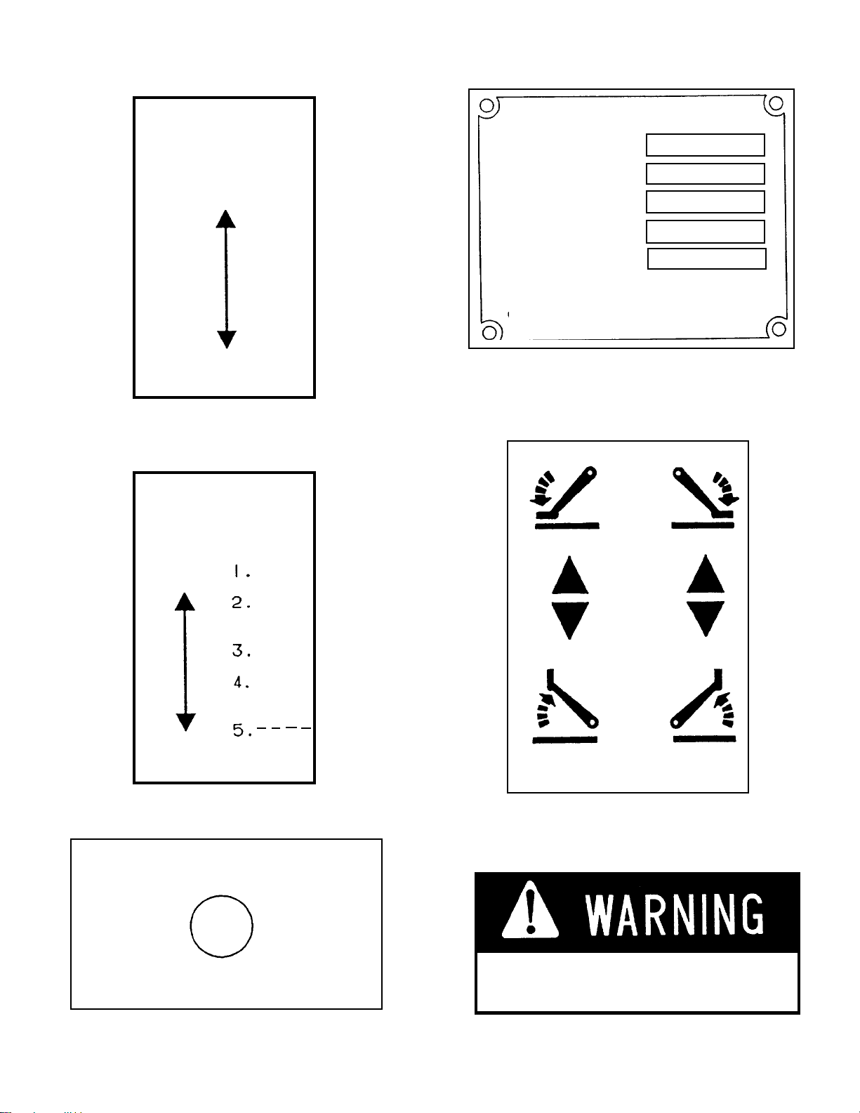
Serial Number Location
Specify Model and Serial Numbers when ordering
parts and when discussing specific applications and
procedures with your distributor. The model/serial
number plate is located on the right cab wall.
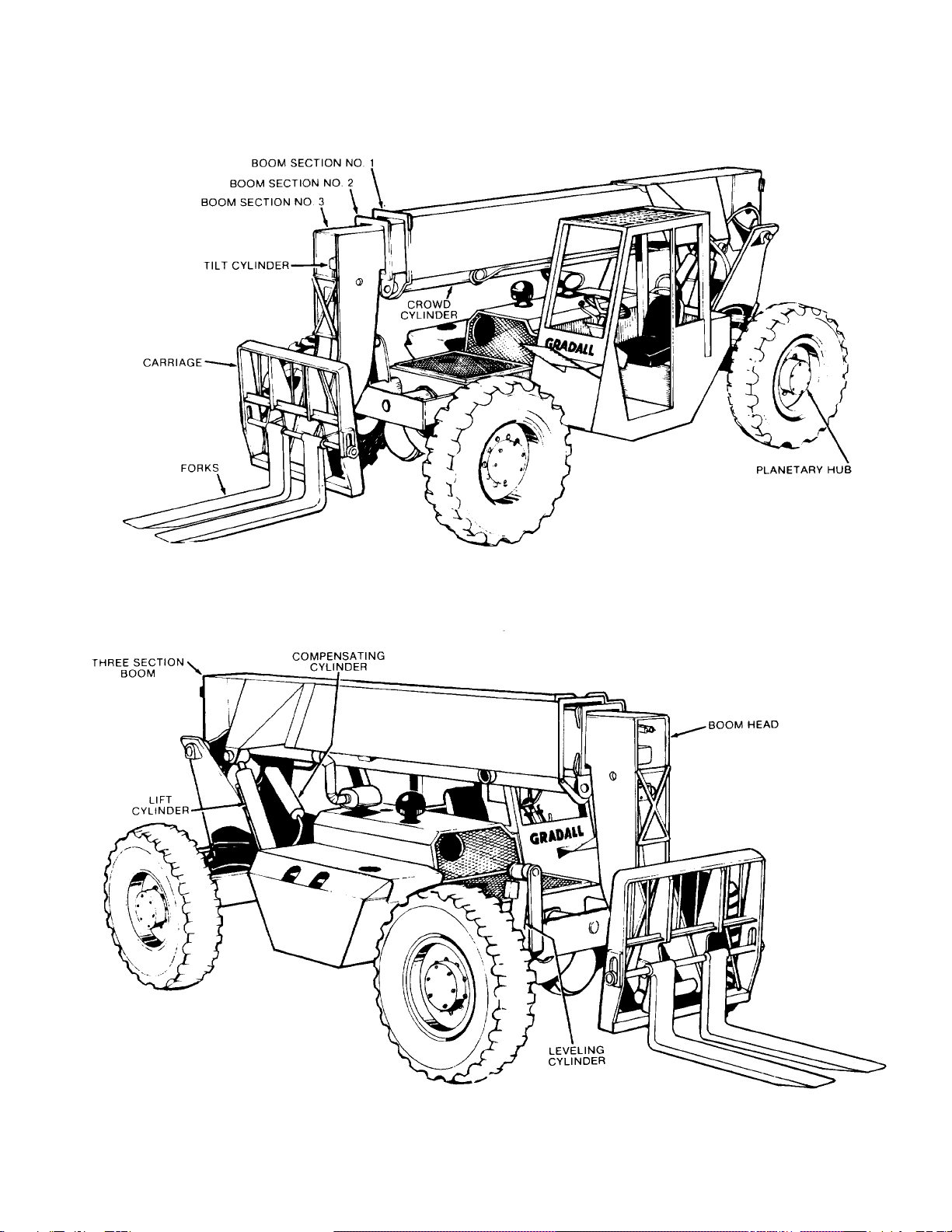
Nomenclature
The illustrations on page 3 include nomenclature
applied to major components of the material handler.
The term “handler” will be used throughout the
balance of this manual in place of the words”material
handler”.
2
*

3
NOMENCLATURE

SAFETY HIGHLIGHTS
Read and understand this manual, the Gradall Ma-
terial Handler Safety Manual and all instructional
decals and plates before starting, operating or per-
forming maintenance procedures on this equipment.
Most safety notes included in this manual involve
characteristics of the Model 534B-9 Material
Handler. Refer to the FIEI Rough Terrain Forklift
Safety Manual and the Gradall Material Handler
Safety Manual for safety precautions relating to
general material handling procedures and practices.
Operators of this equipment must have successfully
completed a training program in the safe operation
of this type of material handling equipment.
Regardless of previous experience operating similar
equipment, the operator must be given sufficient
opportunity to practice with the 534B-9 Material
Handler in a safe open area(not hazardous to people
or property)to develop the skills and”feel”required
for safe, efficient operation.
Watch for these symbols; they are used
to call your attention to safety notices.
This symbol indicates an extreme hazard which
would result in high probability of death or
serious injury if proper precautions are not
taken.
This symbol indicates a hazard which could
result in death or serious injury if proper
precautions are not taken.
This symbol indicates a hazard which could
result in injury or damage to equipment or
property if proper precautions are not taken.
4

Located on Dashboard
PartNo.9100-3039
9100-3039
Decals
9103-3089
Located on Dashboard
PartNo.9103-3089
9100-3040
Located on Dashboard
PartNo.9100-3040
Located on Boom Lever Knob
PartNo.9100-3044 Located on Right Cab Wall
Part No.9103-3279
5

Decals (cont.)
Located on Dashboard
PartNo.9103-3341
FOR LONGER TURBOCHARGER
LIFE,IDLE ENGINE AT LEAST
I MINUTE AFTER START-UP
AND BEFORE SHUT-DOWN.
TO PREVENT ENGINE RING
GEAR DAMAGE, WAIT 10
SECONDS AFTER ENGINE
STOPS BEFORE ATTEMPTING
TO RESTART.
FOROPTIMUMCONTROLANDBRAKE
LIFE, US LOW GEAR WHEN
DESCENDING STEEP GRADES.
Located on Dashboard
PartNo.9103-3443
WHEN TRAVELLING AT HIGH SPEEDS
FOR OVER 2 MILES, DISENGAGE
REAR HUBS BY REVERSING SMALL
COVER PLATE AT HUB CENTER.
9103-3418
Located on Dashboard
PartNo.9103-3418
Located on Left Cab Wall
PartNo.9103-3396
534B-9
9103-3395
Located on Mudguard
PartNo.9103-3395
6

Decals (cont.)
IMPORTANT
To prevent damage to the electrical system when
using booster battery or charger, always connect
(+)POSITIVETOPOSITIVE
( -) NEGATIVE TO NEGATIVE
Located on Battery Cover
PartNo.7702-3007
HOT EXHAUST
Located on Engine Cover
PartNo.7734-3018
DEATH
OR INJURY MAY RESULT FROM
CONTACTINGELECTRICALLINES.
UNLAWFUL
TO PLACE ANY PART OF THIS
MACHINE OR LOAD WITHIN 10
FEET OF HIGH VOLTAGE LINES
OF UP TO 50,000 VOLTS.
Located on Mudguard
PartNo.8360-1011
PARK BRAKE
PULL TO SET
PUSH TO RELEASE
Located on Seat Pedestal
PartNo.9104-3129
PARK BRAKE
OFF ON
DO NOT ENGAGE PARK
BRAKE WHILE MACHINE IS IN
MOTION - STATIC BRAKE ONLY
Located on Dashboard (Recent units)
PartNo.9108-3269
7
HYDRAULICOIL
7702-3006
Located on Hydraulic Reservoir
PartNo.7702-3006
Located on Boom
PartNo.9100-3031
Located on Right Cab Wall
PartNo.9106-3047
FUEL - DIESEL
EXTINGUISH ALL OPEN FLAME
AND SMOKING MATERIALS
WHEN REFUELING 9100-3052
Located on Fuel Tank
PartNo.9100-3052

Decals (cont.)
DO NOT INSERT HAND IN
OPENING WHILE ENGINE
IS RUNNING 9103-3011
Located on Engine Cover
PartNo.9103-3011
DO NOT USE OXYGEN
USE “OIL PUMPED OR DRY NITROGEN.”
CONSULTDEALERBEFORECHARGINGACCUMULATOR
9104-3206
Located on Accumulator
PartNo.9104-3206
PINCH POINT AREA
TO PREVENT INJURY, KEEP
CLEAR ANYTIME MACHINE
IS RUNNING. 9104-3209
Located on Rear of Frame
PartNo.9104-3209
TO PREVENT
INJURY, KEEP
OUT OF BOOM
HOLES.
Located on each side of boom
PartNo.7702-3009
7702-3009
8
PRESSURIZED-
COOLINGSYSTEM
REMOVE CAP
SLOWLY
9104-3210
NO RIDERS
9104-3211
Located at Cab Entrance &
on Engine Cover
Part No. 9104-3211
Located on Engine Cover
Part No. 9104-3210
DO NOT USE THIS MACHINE
FOR LIFTING PERSONEL.
Located on Mudguard
PartNo.9104-3215
9104-3215
INSURE FORKS ARE LEVEL AND
LOAD IS SECURE BEFORE ROTATING
LOAD WHEN EQUIPPED WITH SWING
FORKS. BOOM SHOULD BE PROPERLY
SHIMMED TO MINIMIZE TWIST.
LOSS OF LOAD WILL RESULT FROM
MISSUE OF SWING FORKS. 9104-3173
Located on left cab wall
PartNo.9104-3173

Optional Equipment Decals
AUXILIARY CONTROLS
LEVER
OPERATION
LEFT/DOWN
RIGHT/UP
9103-3417
Located on Instrument Console
PartNo.9103-3417
AUXILIARYCONTROLS
LEVER BUTTON
OPERATION FUNCTIONS
LEFT/DOWN
9
Located on Instrument Console
PartNo.9103-3394
ENERGIZE WHILE STARTING
ETHER
Located on Dashboard
PartNo.9108-3363
RIGHT/UP
CHECK TO ASSURE QUICK SWITCH
PIN IS FULLY ENGAGED AND LOCKED
AFTER ATTACHMENT CHANGE.
Located on Boom Head
PartNo.9103-3023
Located on Seat Pedestal
PartNo.9102-3006
Located on Attachment
PartNo.9015-3001
GRADGRAD
GRADGRAD
GRADALLALL
ALLALL
ALL
•
406 HILL AVE. S.W. NEW PHILADELPHIA. OHIO MADE IN U. S. A.
THECAPACITYOFFORKLIFT.ATTACHMENTANDFORK
COMBINATIONMAYBELESSTHANTHECAPACITYSHOWN
ONATTACHMENT-CONSULTFORKLIFTNAMEPLATE
ANDALSOINSUREFORKSAREOFPROPERSIZE.
9103-3394
ATTACHMENT
SERIAL NUMBER
WEIGHT
CAPACITY
HYD. PRESSURE
9102-3006
2-9103-3023
9015-3001
MAST
SIDE
SHIFT
SWING
PANEL
SUPPORT

OPERATOR’S CAB
The standard cab is open on three sides and includes
an overhead guard to provide protection from
falling objects.
Never operate the handler unless the
overhead guard is in place and in good
condition.
A fully enclosed cab with windows and a lockable
door is available as an option. The cab door can be
sure the door is fully secured when operating the
handler.
The operator’s seat is equipped with a seat belt and
includes fore and aft adjustment to compensaste for
variations in operator size. The adjustment
release/lock lever is located beneath front edge of
seat. Wear seat belt at all times.
An optional windshield wiper is available for use
with enclose cabs. An ON/OFF control switch is
located on the wiper motor.
A variable speed defroster fan is available for use
with enclose cabs. An ON/OFF control switch and
speed control are located on the base of the fan.
An optional variable speed heater fan is available for
use with units equipped with a heater. An ON/OFF/
SPEED CONTROL knob is located on the dash-
board.Hot water to the heater can be controlled by a
valve at the engine.
CONTROL AND INSTRUMENT IDENTIFICATION
*Items preceded by an asterisk are optional and may not be furnished on your handler
10

NOTE: These descriptions are provided in alphabet-
ical sequence in accordance with the nomenclature
shown on the facing page.
Accelerator Pedal: The accelerator pedal is connect-
ed to the engine speed control by a cable to provide
engine speed control. Depress pedal to
increase speed and release pedal to decrease speed.
Ammeter: The ammeter indicates the charge/dis-
charge rate of the battery charging system. With the
engine running, a discharge reading or a continuing
high charge rate indicates a problem in the system.
Auxiliary Control Lever (optional): This lever is used to
control optional hydraulic attachments. Follow decal
instructions for lever/handler movements.
Boom Extend/Retract Lever: This lever controls boom
extension and retraction. Speed is proportional to
lever actuation. Move lever to right to extend boom or
to left to retract boom.
Boom Raise/Lower Lever: This lever controls raising
and lowering the boom.Speed is proportional to lever
actuation. Pull lever to rear to raise boom or push lever
forward to lower boom.
Carriage Tilt Lever: This lever controls bit of the fork
carriage. Speed is proportional to lever actuation.
Push lever forward to tilt down or pull lever to rear to tilt
up.
Engine Coolant Temperature Gage: This gage dis-
plays engine coolant temperature. Normal operating
temperature is 180-200°F.(82-93°C.).
Engine Oil Pressure Gage: This gage displays engine
oil pressure. Normal operating pressure is 35-50 psi
(241-345kPa).
Forward/Reverse Lever: This lever engages forward
or reverse travel. Push lever fully forward for forward
travel; pull lever fully to rear for reverse travel or more
lever to centered position for neutral.
Fuel Gage: This gage displays level of fuel in fuel tank.
Heater Fan Switch (optional): This rotary switch con-
trols heater fan. Rotate clockwise to start fan. Con-
tinued clockwise rotation controls fan speed.
A brief description of controls and instru-
ments is provided here as a convenience for
the operator. These descriptions DO NOT
provide complete operating instructions.
Read and understand this manual and the
FIEI Rough Terrain Forklift Safety Manual
before operating the handler.
Horn Button: Depress button to sound horn.
Hourmeter: This meter indicates total time of engine
operation in hours and tenths of hours.
Ignition Switch: This switch is actuated by a key. In ON
position (turned clockwise) voltage is available for all
electrical functions. Full clockwise position engages
starter motor. Turn key counterclockwise to stop
engine and remove voltage from all electrical
functions.
Level Indicator: This indicator (a bubble ievel) enables
the operator to determine the left to right level condition
of the handler.
Machine Level Lever: This lever controls the vertical
relationship of the handler frame to the front axle. Move
the lever to the right to tilt frame to right or move lever to
left to tilt frame to left.
Outrigger Levers: These levers raise and lower out-
riggers. Move levers forward to lower or pull levers to
rear to raise outriggers.
Parking Brake Light: This light glows to indicate that
parking brake is applied or that there is insufficient
pressure to release brake.
Parking Brake Knob: The park brake control knob is
located to the left of the operator and is used to apply
and release the parking brake. To apply the parking
brake,pull the knob up. To release the parking brake,
push the knob down.
Rotating Beacon Switch (optional): This switch con-
trols operation of rotating beacon.
Seat Lock Release Lever: This lever unlocks and locks
seat position adjustment. Lift lever to unlock and
release lever to lock adjustment.
Service Brake/lnching Pedal: The brake/inching
pedal provides service brake control and inching
control. To activate the brakes, push the pedal down.
To release the brakes, remove foot from pedal. When
full brakes are applied, the rear hydraulic drive is
disconnected. When partial brake/inching pedal
movement is used, the front wheel drive is discon-
nected from the transmission. The inching feature of
the rear wheel drive system provides for smooth
machine operation at low speeds and high engine rpm.
Steering Wheel:The steering wheel controls the angle
of rear axle wheels. Turning the steering wheel to the
Forward/Reverse Lever: This lever engages forward
right causes a right turn by angling rear wheels to left.
A left turn is caused by angling rear wheels to right.
Transmission Speed Selector Lever: This lever per-
mits selection of three speed ranges for forward and
reverse travel.
Transmission Temperature Gage: This gage displays
temperature of transmission fluid. Normal operating
temperature is 180-200°F.(82-93°C.).
11

CHECKS AND SERVICES
BEFORE STARTING ENGINE
(To be performed at beginning of each work shift)
Use extreme caution when checking items
beyond your normal reach. Use an
approved safety ladder.
Before removing filler caps or fill plugs, wipe all dirt
and grease away from the ports. If dirt is allowed to
Complete all required maintenance before operating unit.
enter these ports, it can shorten the life of o-rings,
seals, packings and bearings.
When adding fluids or changing filter elements,
refer to the lubrication section of this manual to
determine the proper type to be used.
If spark arrestors are required, be sure they are in
place and in good working order.
Service the unit in accordance with the lubrication
and maintenance schedule.
Inspect unit for obvious damage, vandalism
and needed maintenance. Check for signs of fuel,
lubricant, coolant and hydraulic leaks. Open all
access doors and look for loose fittings, clamps,
components and attaching hardware. Replace
hydraulic lines that are cracked, brittle, cut or show
signs of abrasion.
Inspect all structural members, including attach-
ment, for signs of damage.
12

Starting Engine
Check to be sure that all controls are in neutral
and that all electrical components (lights, heater,
defroster, etc.) are turned off. Set parking brake.
Depress accelerator pedal approximately 1/4 to
1/3 o f travel from top.
Insert ignition key and turn clockwise to ON
position.
ENGINE OPERATION
NOTE: If engine is being started at beginning of work shift be sure to perform all “CHECKS AND
SERVICES BEFORE STARTING ENGINE” (page 12).
Engaging starter motor while engine fly-
wheel is rotating can cause serious damage
to engine and/or starting motor.
NOTE: If temperature requires the use of a starting
installed ether starting aid,depress ether button one
Cold Weather Starting Aids
Diesel engine ignition is accomplished by heat
generated when fuel/air mixture is compressed
within the cylinders. Because this heat may be
insufficient to start a cold engine in cold weather,
the use of starting aids has become common practice.
Because of the wide variety of starting aids available
it would be impractical to attempt to provide.
Normal Engine Operation
Observe gages frequently to be sure all engine
systems are functioning properly.
The ammeter shows the charge/discharge rate of the
battery charging system. With the engine running, a
discharge reading (-) or a continuing high charge
reading (+) indicates a problem in the battery
charging system.
Be alert for unusual noises or vibration. When
an unusual condition is noticed, stop machine in a
safe position and shut off engine. Determine cause
and correct problem before continuing.
time while cranking engine. Repeat if necessary. If
you use a different starting aid, be sure to follow
manufacturer’s instructions carefully. Excessive
ether may damage engine.
Turn key fully clockwise to engage starting
motor. Release key immediately when engine
starts. If engine fails to start within 20 seconds,
release key and allow starting motor to cool for a
few minutes before trying again.
After engine starts, observe oil pressure gage. If
gage remains on zero for more than ten seconds,
stop engine and determine cause.Correct cause of
malfunction before restarting engine. Normal
engine oil pressure (warm) should be in range of
35 - 50 psi (241 - 345 kPa).
Warm up engine at approximately l /2 throttle
until engine coolant temperature reaches
operating range of 180 - 200°F.(82 - 93°C.).
Avoid prolonged idling. Idling causes engine
temperature to drop and this permits formation of
heavy carbon deposits and dilution of lubricating oil
by imcompletely burned fuel. If the engine is not
being used, turn it off.
Always keep engine covers closed while
engine is running (if furnished).
13
specific instructions for their use in thismanual.
Carefully follow instructions furnished with your
starting aid.
If you use a starting aid employing ether or a
similar substance pay particular attention to
manufacturer’s warnings.
1.
2.
3. 4.
5.
6.

Stopping the Engine
Operate engine at idle speed for a few minutes
before turning it off. This allows engine coolant and
lubricating oil to carry excessive heat away from
critical engine areas.
Do not “gun” engine before shut down; this
practice causes raw fuel to remove oil film from
cylinder walls and dilute lubricant in crankcase.
Allow engine to run at idle for a few minutes
to allow the turbo components to cool. Turn
key counterclockwise to stop position and
remove key from ignition switch before
leaving cab.
WARM UP & OPERATIONAL CHECKS
(To be performed at beginning of each work shift)
Complete all required maintenance before operating unit.
The safety, efficiency and service life of your unit will
be increased by performing by an asterisk(*) are
optional and may not be furnished on your machine.
Checks items during warm-up period.
Heater, defroster and windshield wiper
Operating lights and rotating beacon
Low brake pressure light - should go out with
engine running above idle
Ammeter - should show low charging rate after
charging system has replaced starting drain
When engine warms to operating range,check
the following items:
Service brake and parking brake.
Forward and reverse travel in all gears
“Inching” travel - should be smooth through full
pedal travel
Horn and back-up alarm
All boom and attachment functions - full stroke
in both directions
Hydraulic Filter Condition Indicator - observe
transmission torque converter temperature gage
after starting normal operation. when needle
has been in operating range for an hour or so,
stop handler in a safe area and set parking brake.
With engine running at full RPM,check hydrau-
lic filter condition indicator. When yellow flag
fills indicator window, filter is clogged and
hydraulic oil is bypassing filter. Filter must be
changed before reaching bypass condition
(change before yellow flag reaches midpoint of
window).
*1.
*2.
3.
4.
5.
6.
7.
8.
9.
10.
Continued operation with hydraulic fluid
by-passing the filter (yellow flag
showing) can cause severe damage to
hydraulic system components.
14

BRAKE SYSTEM
General
The brake system furnished on the handler includes a
service brake and parking brake.
Because service braking and “inching” (slow travel)
functions overlap, some features of inching will be
discussed here. Refer to Drive Train Section for
additional information on inching travel.
Inching Travel
Overlap between service braking and inching occurs
because the same foot pedal controls both functions,
and also because both functions control travel speed.
However, the methods of controlling travel speed are
quite different: service braking involves a controlled
stopping force applied to the front wheels while
inching involves a controlled driving force applied to
the rear wheels.
The service brake/inching pedal has three separate
functions
It disconnects front drive axle from transmission.
It controls hydraulic flow to rear axle drive motors
(hydraulic flow regulates speed).
It applies service brake.
Service Brakes
The service brake is applied to the front wheels of the
handler.
Oil for the brakes comes from the pilot circuit pump,
thru an accumulator charging valve and the accumu-
lator. When the service brake/inching pedal is
depressed far enough to actuate the brake valve, the
hydraulic oil flows to the wet disc brakes in both
front wheel hubs. The pressure compresses the brake
discs.
As illustrated, the three functions occur in sequence
as service brake/inching pedal is depressed from top
to bottom of stroke.
Practice inching/braking in a safe, open
area until you are thoroughly familiar with
response of machine to pedal travel.
15
Parking Brakes
Because the parking brake is spring-applied and
hydraulically released,the engine must be running to
provide pressure to release parking brake.
On early units the parking brake is applied and
released by a control valve knob located to the left of
the operator’s seat. Raise knob to apply brake and push
knob down to release brake.
On recent units the parking brake is applied and
released by a switch located on the dashboard. Depress
right side of switch to apply brake and depress left side
of switch to release brake.
Always be certain to apply parking brake, stop engine
and remove key from ignition switch before leaving
operator’s cab.
1.
2.
3.

STEERING SYSTEM
Ninety degree rear wheel power steering is provided
to reduce operator fatigue and to permit high
maneuverability in close quarters.
It is important that the operator practice
maneuvering the handler in a safe, open area until
he becomes thoroughly familiar with steering
response and clearance required for tailswing and
load when turning.
Be alert for any increase In effort needed to
steer. If any difference is noted, notify
maintenance personnel immediately for
correction. If power assist feature should
fail for any reason IT WOULD BECOME
VERY DIFFICULT TO STEER. For this
reason it is extremely important that you
NEVER TURN ENGINE OFF WHILE
TRAVELING.
In the event power steering fails, stop as
soon as possible. Do not drive unit until
problem has been corrected.
FRONT OUTRIGGERS (2) (OPTIONAL)
Front outriggers are provided in order to raise the
front tires off of the ground level while working, thus
improving the overall stability of the handler.
Two outrigger control levers are located to the right
hand side of the operator’s seat. Pushing forward on
the lever lowers the outriggers, and pulling back on
the lever raises them.
16

General
The drive train provides two and four wheel drive
includes the engine torque converter trans-
mission drive shaft and front and rear driving axles.
Inching travel is directly related to drive train
functions and will be discussed in this section.
Two & Four Wheel Drive
The drive train is designed to provide two wheel
drive (front axle driving? or four wheel drive (both
front and rear axles driving).
Under certain conditions changing from four wheel
drive to two wheel drive may cause a difference in
the way the machine responds to steering braking
and drive controls. Always be aware of which travel
mode you are using.
There are two ways to disengage rear wheel
drive:
Shift to third gear (rear axle drive is engaged only
in first and second gears)
Disengage rear planetary hubs (refer to Rear
Drive Axle heading in this section).
NOTE: Rear drive axle can also be disengaged in
response to overload in associated electrical circuitry
causing automatic reset type circuit breaker to trip
(open). Breaker will close again in approximately ten
seconds.
Torque Converter
There are no operator controls for the torque
converter. It functions automatically to permit
starting from a standstill in any transmission speed
range.
An oil temperature gage is provided to indicate
Operating temperature of torque converter/trans-
mission. Normal operating temperature is 180 -
200 ° F. (82 - 93 ° C.). If overheating occurs attempt
to lower temperature by traveling in a lower gear. If
necessary stop and allow torque converter to cool
with engine running and gear selector in neutral. Be
sure oil cooler radiator fins are clean.
DRIVE TRAIN
Transmission
The transmission provides three speed ranges for
both forward and reverse travel.
There are three operator controls for the
transmission:
Gear Selector Lever (for 1st 2nd and 3rd gears).
Direction Selector Lever (for forward neutral
and reverse).
Service Brake/Inching Pedal (refer to Inching
Travel heading in this section).
To Operate Transmission:
Release parking brake and hold handler in posi-
tion using service brake.
Move gear selector to appropriate speed range
(1st 2nd or 3rd gear). The gear selector may be
shifted while traveling. When traveling downhill,
use the same gear needed to travel up the hill.
Never shift gear selector or direction
selector to cause a sudden change of
travel speed or direction. Such a change
could cause load to shift or machine to tip
over. Reversing direction while traveling
can also damage transmission.
Move direction selector to forward or reverse
position as required.
Release service brake and depress accelerator to
attain appropriate speed.
Stop handler by releasing accelerator and
applying service brake.
Move direction selector to neutral position.
Apply parking brake.
Front Driving Axle
The front driving axle includes a differential and
planetary drive hubs and is powered by a drive shaft
from the transmission. The service brake/inching
pedal is the only operator control for the front axle
(refer to inching travel heading).
3.
4.
5.
6.
7.
Continued operation of overheated torque
converter/transmission can cause serious
damage to these components.
1.
2.
1.
2.
*With rear planetary hubs disengaged
1.
2.
3.
17

Rear Driving Axle
The rear driving axle includes planetary hubs which
are powered by hydraulic motors mounted on the
inner face of the hubs. Hydraulic flow to drive
motors is provided only in first and second gear
speed ranges. Drive motors are free- floating in third
gear.
Continuous driving for two miles or more
in third gear, with rear driving hubs
engaged, can damage hydraulic drive
motors.
To Disengage Rear Driving Hubs:
Apply parking brake and remove key from
ignition switch.
Remove cap screws from pin keeper plate.
Remove and rotate plate (cup out - engaged - cup
in - disengaged).
Secure plate using cap screws.
Repeat procedure for other hub.
To engage Rear Driving Hubs: Repeat procedure.
NOTE: If machine is move with pin keeper plate
removed, input shaft pin will pop out.
Hydraulic flow to rear axle drive motors is controlled
electrically. An automatic reset type breaker is
included to prevent damage from overload. If circuit
breaker trips (opens) rear axle drive will be
inoperative for approximately ten seconds until
breaker resets. Notify maintenance personnel if
circuit breaker trips repeatedly.
To determine whether circuit breaker has tripped,
attempt to move machine using inching travel. If
machine does not respond to inching travel pedal.
circuit breaker is open.
Inching Travel
Inching travel is provided to permit very slow travel
while maintaining high engine speed for other
functions. Because inching travel depends on
hydraulic flow to rear axle drive motors, inching
1.
2.
3.
4.
5.
travel functions only in first and second gears. There
is no hydraulic flow to drive motors in third gear.
Inching travel is controlled by the service
brake/inching travel pedal. This pedal has three
separate functions:
It disconnects front drive axle from transmission.
It controls hydraulic flow to rear axle drive motors
(hydraulic flow equals speed).
It applies service brake.
1.
2.
3.
As illustrated,the three functions occur in sequence
as pedal is depressed from top to bottom of stroke.
To Engage Inching Travel:
Depress service brake/inching travel pedal
approximately 1-1 /2 inches to disengage front
driving axle from transmission. At this point rear
drive motors are receiving full flow and travel
speed will not have changed.
Continue to depress pedal to reduce speed - the
more pedal travel, the less speed.
To stop, depress pedal fully.
To resume normal travel, release service brake
inching travel pedal. Depress accelerator pedal to
attain appropriate speed.
OR
Practice inching/braking in a safe, open
area until you are thoroughly familiar with
response of machine to pedal travel.
1.
2.
3.
18

“LEVELING” means positioning the handler so that
it is level from side to side (left to right with respect to
a man sitting in operator’s seat).
A level indicator is located on upper portion of front
window frame to permit operator to determine that
handler frame is, or is not, level.
There are four very important things to remember
about handler travelling:
Never engage a load or lift a load more than four
feet above ground level unless the handler is level.
A handler with the boom raised and/or an attach-
ment installed is a partially loaded handler.
Once the handler frame has been leveled, and has
raised a load more than four feet above ground
level, it must not be moved from its position if
such movement could change the level condition.
The combination of side tilt and load can cause the
handler to tip over.
There are two ways to level the handler:
The surface which will support the handler can be
leveled. This method must be chosen if it will be
necessary to move the handler from its position
after the load has been raised over four feet from
ground level - AND - such movement could
change the level condition.
Remember, the supporting surface must be large
enough , smooth enough and firm enough to keep
handler level when it is moved from its position.
The handler may be leveled by means of the frame
leveling system. This method may be chosen when
it will not be necessary to move the handler from
its position after the load has been raised above
four feet from ground level - OR - when such
movement will not change the level condition of
the handler.
LEVELING THE HANDLER
Leveling Handler Frame:
The handler is designed to permit tilting main frame
eight degrees to left or right to compensate for
uneven ground conditions.
The rear axle pivots at the midpoint of the main
frame to help assure that wheels will remain in
contact with ground. A hydraulic cylinder provides
a rigid connection between front axle and main
frame to help assure a solid work platform and
permit tilting main frame to left or right.
Procedure:
Position machine in best location to lift or place
load and apply parking brake.
Observe level indicator to determine whether
machine must be leveled. Note position
indicator for later realignment.
If necessary to level handler, position boom in
carry position and move machine level lever to
levelmachine.
Lift or place load as appropriate.
Retract and lower boom to carry position.
Realign frame to position noted in step 2.
FRAME
LEVELING LEVER
If handler cannot be leveled using leveling
system, do not attempt to raise or place
load. Have surface leveled.
1.
2.
3.
4.
19
Always determine best positions for handler to raise
load from its present location and also to position
load at its destination. THEN, determine which
method of leveling will be required at each location.
FINALLY,consider terrain between present location
of load and its destination.Never attempt to transport
a load across terrain which could cause handler to tip
over.
1.
2.
Raising the boom (loaded or unloaded)
when handler is leaning to the side can
cause machine to tip over with little or no
warning and cause serious injury or death.
Table of contents
Other Gradall Forklift manuals
Popular Forklift manuals by other brands

Hyster
Hyster H16.00-18.00XM Service & repair manual

cascade corporation
cascade corporation F Series user manual

Jungheinrich
Jungheinrich ESC 316z operating instructions

Pramac
Pramac GX Series Use and maintenance manual

Big Joe
Big Joe M22 Installation, operation, maintenance & repair parts

Xtreme
Xtreme XR1267 Operation & safety manual