ROUBLESHOOTING
6083966-R4
T
6
3.3 Fork Position Function
Five potential problems can affect the fork positioning
function:
• Binding due to bending damage, wear, lack of
lubrication.
• Incorrect hydraulic pressure or flow from truck.
• Flow restrictor fittings plugged or improperly
adjusted.
• Solenoid equipped: Electrical circuits faults, defective
solenoid coil or valve.
• External leaks due to worn or defective cylinder
seals.
3.3-1 Supply Circuit Test
1 Check the pressure supplied by the truck at the
carriage hose terminals. Pressure must be within
the range shown in Specifications, Section 5.1.
PRESSURE TO THE FORK POSITIONER MUST NOT
EXCEED 3500 psi (241 bar).
2 Check the flow volume at the carriage hose terminal.
Flow must be within the range shown in Specifications
Section 5.1.
3 Fully open the forks. Hold the lever in the OPEN position
for several seconds. Release the lever and check for
external leaks at the fittings, tubing, hose, and manifold.
3.3-2 Fork Position Circuit Test
1 If equipped, press the solenoid button. Listen for a
'click' as the solenoid valve. If no sound is heard, check
the fuse, wiring and coil. Repair as necessary.
IMPORTANT: Solenoid-operated valve should be
plumbed so that the solenoid is energized during the
fork-positioning function.
2 Fully open or close the forks. If the forks move
unevenly, slowly or not at all, check flow restrictors for
contamination or improper adjustment. Refer to Section
4.1. Speed should be 3 in. (75 mm) per second at
specified flow rate.
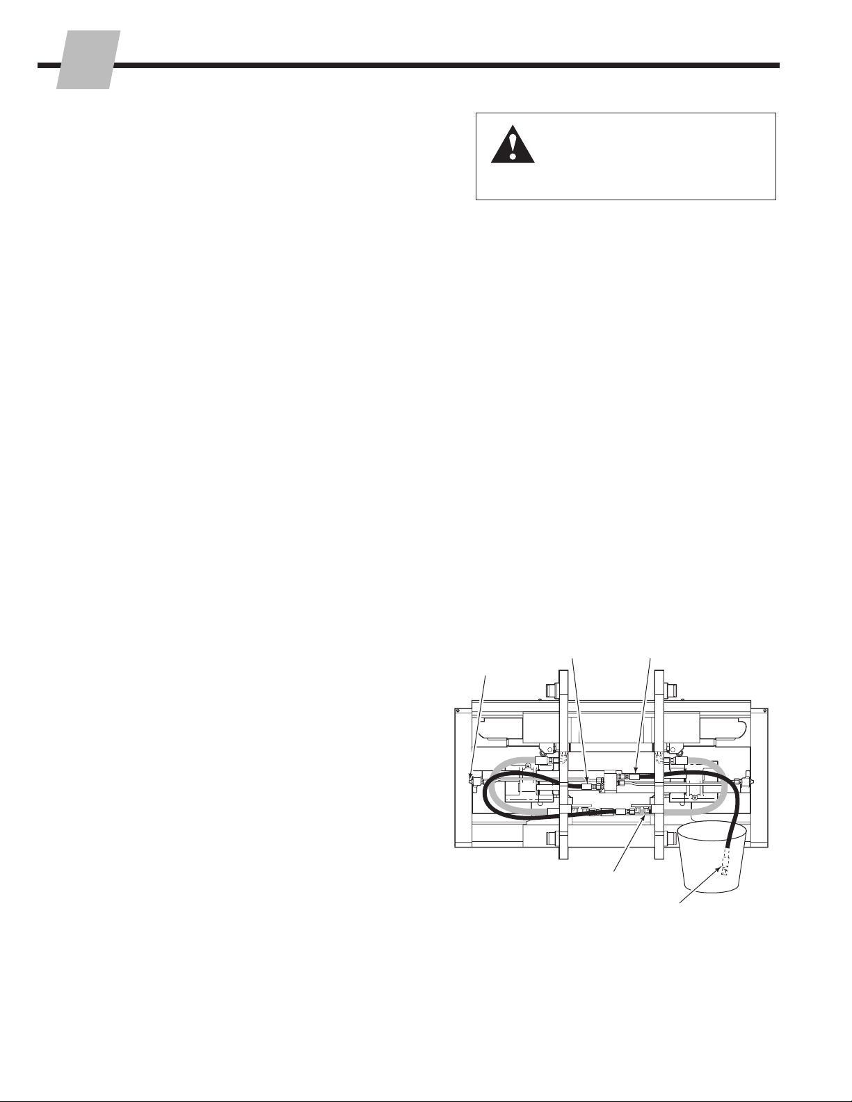
3 If forks still do not move correctly, fully close forks. Turn
the truck off. Relieve the attachment's system pressure.
Disconnect the OPEN supply hose from the truck hose
terminal and route to a drain bucket. Cap the supply
fitting.
4 Start the truck and slowly actuate the CLOSE forks lever
until forks are fully closed. Hold lever for 5 seconds.
• If there is substantial hydraulic flow out of the drain
hose, one of the cylinders has faulty piston seals.
Replace the complete unit or service the piston seals
(see Section 4.2).
• If there is little or no hydraulic flow out of the hose,
the problem is not hydraulic. Refer to Section 3.3.
FP1121.eps
Flow Restrictors
(each end)
2
3
CLOSE Forks
Supply Hose
OPEN Forks
Supply Hose
Cap supply fitting
Hose end in
the bucket
Back (Driver's) View
WARNING: Before removing any
hoses, relieve pressure in the hydraulic
system. With the truck off, open the
truck auxiliary control valve(s) several
times in both directions.