Linde E 20-02 User manual

With Electric Motors
336 804 3001 GB
E 20 - 02 / E 25 - 02 / E 30 - 02
E 20/600 - 02 / E 25/600 - 02 / E 30/600 - 02
Operating Instructions
0704
Linde Fork Lift Truck
e336-02/01


Linde - Your Partner Linde AG Linde Material Handling Division
Linde, an enterprise operating
worldwide in the investment
and service sector, is one of
the large industrial enterpris-
es in the EC with its three
business segments and six
divisions.
The Linde Material Handling
division is a leading manufac-
turer of industrial truc s and
hydraulics. It includes eight
manufacturing plants in the
Federal Republic of Germany,
France and Great Britain, as
well as subsidiaries and bran-
ches in all economically im-
portant countries.
Linde industrial truc s enjoy a
worldwide reputation - than s
to their high quality in engin-
eering, performance and serv-
ice.
Werk II, Aschaffenburg-Nilkheim
Werk I, Aschaffenburg
Lansing Linde Ltd., Basingstoke
Fenwick-Linde, Ch tellerault
Werk III, Kahl am Main Linde Heavy Truck Division Ltd., Merthyr Tydfil

2
336 804 3001.0704
Foreword
Your Linde lift truck
offers the best in economy, safety and driving convenience.
Therefore it is mainly in the hands of the operator to preserve
the q alities of the tr ck for a long and profitable service life
and to make f ll se of their benefits on the job.
These operating instr ctions tell yo all yo need to know
abo t starting, operation, r nning and servicing the tr ck.
For maintenance and repair work not described in these
operating instr ctions special technical skill and knowledge,
meas ring eq ipment and special workshop tools are often
req ired. Please contact yo r a thorised Linde dealer for this
service.
Only q alified persons (experts) a thorised by Linde are
allowed to service the tr cks.
For some attachments, the proprietary operating instr ctions
s pplied with them are applicable.
Follow all tips for operating the lift tr ck and carry o t the
maintenance and care prescribed in the inspection and
maintenance sched le reg larly, on time and with the spec-
ified l bricants.
To keep yo r warranty valid, all maintenance services m st
be performed by q alified persons a thorised by Linde.
The terms “front”, “rear”, “left” and “right” refer to the position
in which the item concerned is installed in the tr ck in relation
to the forward travel direction.
Approved applications
Linde lift tr cks are designed for transporting and lifting the
loads stated in the load capacity diagram.
In partic lar, we refer to the VDMA booklet “R les for the
Normal and Proper Use of Ind strial Tr cks”, to the accident
prevention r les of yo r employer’s liability ins rance and
the special meas res for driving on p blic roads.
The r les for se of ind strial tr cks m st be followed nder
all circ mstances by the responsible persons, especially by
the operating and service personnel.
The ser, and not Linde, is responsible for any danger arising
from applications not a thorised by the man fact rer.
If yo desire to se the tr ck for applications not mentioned
in the man al and convert or s pplement it for this p rpose,
please first contact yo r a thorised Linde dealer.
No changes, especially conversions or modifications, may
be made on yo r fork tr ck witho t the prior permission of the
man fact rer.

3
336 804 3001.0704
Foreword
Truck takeover
Every fork tr ck ndergoes caref l inspection before leaving
the factory in order to make s re that it will be in satisfactory
condition and f lly eq ipped as ordered when delivered to
the c stomer. A thorised distrib tors are nder obligation to
reinspect the tr ck before delivery and to hand it over in good
order. In order to avoid later complaints and inconvenience
to c stomers, yo are req ested to ascertain that the tr ck is
in satisfactory condition and f lly eq ipped at the time of
delivery and to acknowledge orderly handing/taking over of
the tr ck in the man fact rer’s certificate of conformity.
The following technical man als are s pplied with each fork
tr ck:
1 Operating man al
1 EC certificate of conformity
(The man fact rer certifies that the ind strial tr ck con-
forms to EC g idelines for machines)
1 R les for the normal and proper se of ind strial tr cks
(VDMA)
Wishing yo satisfactory operation and m ch s ccess,
Yo r
Linde AG
Linde Material Handling Division
Aschaffenb rg
Technical note
These operating instr ctions or excerpts thereof may only be
copied, translated or transmitted to third parties after prior
written approval by the man fact rer.
Linde p rs es a policy of contin o s progress in the design
and constr ction of its prod cts. As a res lt, the ill strations
and technical details referring to design, fittings and
engineering of lift tr cks are s bject to change if progress
warrants it.
Therefore, the man fact rer will not accept any claims based
on the specifications, ill strations and descriptions contained
in this operating man al.
Please s bmit all enq iries concerning yo r fork tr ck and all
orders for spare parts to yo r a thorised distrib tor, making
s re to state yo r correct shipping address.
For repairs, se only gen ine Linde spare parts to ens re that
yo r Linde fork tr ck will maintain its original technical standard.
When ordering spare parts, it is important also to give the
following information:
Lift tr ck model: __________________________________
Man fact rer’s serial no./Year b ilt: __________________
Handing-over date: _______________________________
Also specify the man fact rer’s n mber of the mast when
ordering parts.
Mast no.: ________________________________________
Mast lifting height: ____________________________ mm
When taking over the fork lift tr ck, transfer the data from the
assembly type plates into this operating man al.

336 804 3001.0704
4

5
336 804 3001.0704
12
5
4
3
9
8
10
76
Type plate
1 Vehicle identification plate
2 Man fact rer
3 CE symbol
(The symbol certifies that EC g idelines for machines
and all applicable g idelines are f lfilled.)
4 Serial No./year
5 Unladen mass
6 Battery voltage
7 Min. battery mass
8 Max. battery mass
9 Rated capacity
10 Type
11 Mast n mber (gl ed)
12 Working hydra lics and power steering p mp motor
type plate
13 Red ction gearbox, left
14 Drive motor, left
15 Drive motor, right
16 Red ction gearbox, right
17 Man fact rer’s plate (stamped)
Description

6
336 804 3001.0704
Fork lift truck models E 20 / E 25 / E 30 / E 20/600 / E 25/600 / E 30/600 Description
e336-02/01
Advanced technology,
simple and ergonomic operation,
energy saving, environment-conscio s and minimal mainte
nance,solid man fact re
and for availability of yo r lift tr ck
nearly all parts are available from Linde.
The s ccess of a company
with abo t 9600 employees in eight plants.
The driver’s position and the controls are arranged in accord-
ance with state-of-the-art h man engineering. The arrange-
ment and operation of each control is adapted to the driver so
that fatig e-free and therefore safe working is ens red.
Of co rse, this incl des theeasily operated hydrostatic power
steering with non-ret rn lock, the service-proved do ble-
pedal control - forward travel with the right accelerator pedal,
reverse travel with the left- and only one central control lever
for all lift mast f nctions.

7
336 804 3001.0704
Table of contents Description
Page PagePage
Foreword......................................................................... 2
Approved applications ........................................................ 2
Technical note ..................................................................... 3
Tr ck takeover ..................................................................... 3
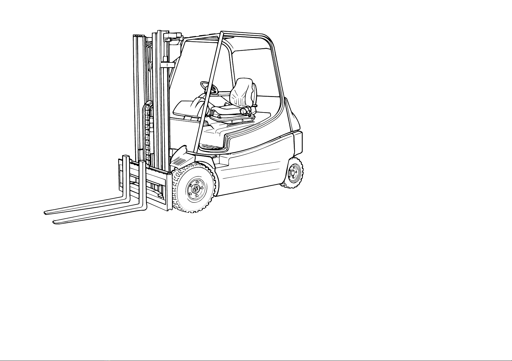
Description ..................................................................... 5
Type plate ............................................................................ 5
Technical data ................................................................... 10
Noise emissions levels ..................................................... 12
Freq ency characteristic for h man body vibrations ......12
Technical description ........................................................ 13
Drive ...............................................................................13
Steering..........................................................................13
Hydra lic system ........................................................... 13
Operation ....................................................................... 13
Brakes ............................................................................ 13
Handbrake ..................................................................... 13
Br sh monitor................................................................. 13
Electrical system ............................................................ 13
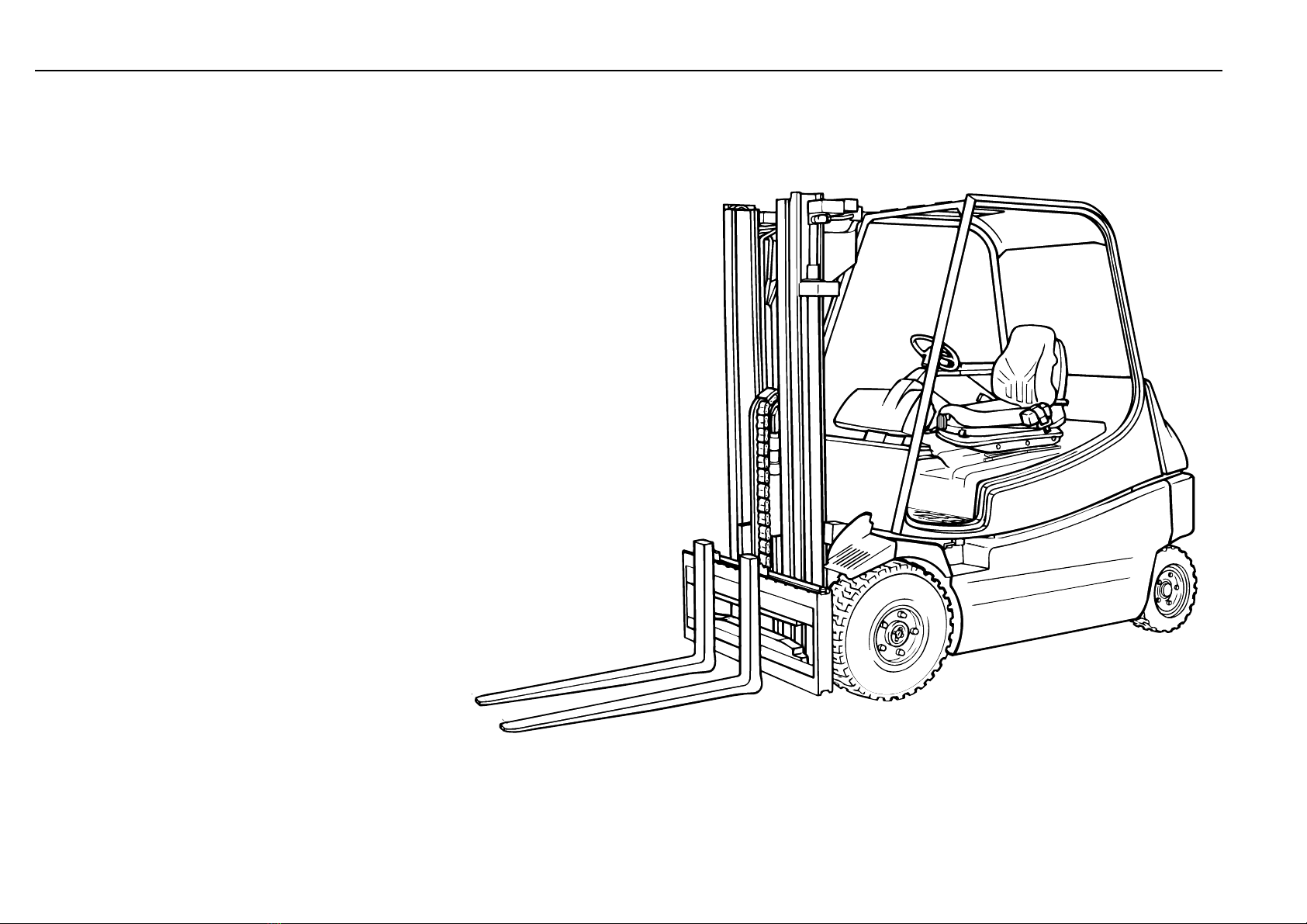
General view of tr ck ....................................................... 14
Controls and indicators .....................................................15
Composite instr ment .......................................................16
Ho r meter ..................................................................... 17
Battery discharge indicator............................................ 17
Before operation ........................................................ 18
Safety r les ........................................................................18
Safety information .............................................................18
Handling fl ids and l bricants.......................................... 18
Accident prevention check................................................ 19
Operation of ind strial tr cks in the plant area ................ 19
R nning-in instr ctions ..................................................... 19
Checks and services prior to initial operation of the
tr ck ................................................................................ 19
Daily checks ...................................................................... 19
Daily checks and servicing before operation .................. 21
Check the tyre inflation press re ...................................... 21
Check the tightness of the wheel n ts.............................. 21
Opening the overhead g ard ........................................... 22
First lock-in position: Servicing position ....................... 22
Second lock-in position: Battery change ...................... 22
Closing the overhead g ard ............................................. 23
Check the battery charge ..................................................24
Charging the battery ......................................................... 24
Connecting the battery to a s itable external charger ....25
Check the condition, electrolyte level and specific
gravity of the battery ......................................................25
Battery change .................................................................. 26
Battery removal with a crane .........................................26
Adj sting the driver’s seat ................................................27
Adj sting the swivel seat ..................................................27
Adj sting armrest of the driver’s seat ...............................27
Applying the seat belt, opening the seat belt ...................28
P sh, p ll the emergency stop b tton .............................. 29
Operation ...................................................................... 30
Driving ...............................................................................30
Travel in the forward direction ......................................30
Travel in the reverse direction ......................................30
Reversing direction .......................................................31
Reversing the direction of travel ................................... 31
Malf nctions d ring operation ......................................31
Singel-pedal model .......................................................... 32
Steering system .................................................................34
Steering..........................................................................34
Braking system .................................................................. 35
Service brake, regenerative brake................................ 35
Foot brake ...................................................................... 35
Operating the electric motor brake (LBC) ..................... 35
Handbrake ..................................................................... 35
Engaging the handbrake............................................... 35
Releasing the handbrake .............................................. 35
Central control lever (joystick) operation of mast
and attachments ............................................................ 36
Tilting the mast forward ................................................. 36
Tilting the mast back ...................................................... 36
Raising the fork carriage ............................................... 36
Lowering the fork carriage ............................................36
Operating the attachments ............................................ 36
Operating the sideshift ..................................................36
Operating the clamp ...................................................... 36
Single control lever operation of mast and attachments .37
T rning on the front working lights ...................................38
T rning on the rear working lights ....................................38
T rning on the front windscreen wiper and washer ........38
T rning on the rear windscreen wiper ............................. 38
T rning on the lighting ...................................................... 38
T rning on the hazard warning light ................................ 38
T rning on the directional indicator lights........................38
Electric heater ................................................................... 39
Tr ck Data Management (LFM) ........................................ 40
Tr ck data acq isition ................................................... 40
Condition code .............................................................. 40
Tr ck data acq isition - defa lt setting
(PIN n mber and condition code) ................................. 41
Tr ck data acq isition - special setting (PIN n mber) .42
Operating the horn ............................................................ 43
Opening, closing the electrical compartment cover ........ 43
F ses ................................................................................. 44
Checking, renewing the f ses ......................................44
A tomotive f ses ........................................................... 44
Main circ it f ses ........................................................... 44
F ses (options) ..............................................................45
Before loading ...................................................................46
Positioning the forks ......................................................... 47
Loading ............................................................................. 47
Transporting the load ........................................................ 48
Unloading.......................................................................... 48
Before leaving the lift tr ck nattended ........................... 48
Tow co pling ..................................................................... 49
Forced opening of overhead g ard witho t Bowden
cable ............................................................................... 49
Transport, Hoisting the tr ck.............................................50
Transporting the tr ck on a lorry or low-bed trailer ......50
Hoisting the tr ck with a crane ......................................50
Hoisting the tr ck with the eyebolts .............................. 50
Wheel change ...................................................................51
Jack locations: Changing the rear, front wheels ............. 51
Mast removal ..................................................................... 52
Towing instr ctions ........................................................... 52
Towing proced re ............................................................. 52
Tilting the mast man ally .................................................. 53
Lowering the forks man ally .............................................53
Emergency exit for tr cks with rear windscreen ..............54
Emergency exit for tr cks with polycarbonate rear
windscreen (special eq ipment)................................... 54

336 804 3001.0704
8

9
336 804 3001.0704
Table of contents Description
PagePage
Maintenance ............................................................... 55
Taking the tr ck o t of operation ...................................... 55
Meas res before taking the tr ck o t of operation ..........55
P tting the tr ck back into operation ................................55
General information .......................................................... 55
Maintenance intervals ...................................................... 55
Work on the mast and on the front part of the tr ck .........56
Sec ring the mast against tilting back ............................. 56
Mast versions ....................................................................56
Standard mast ................................................................... 56
Sec ring the raised standard mast ..................................56
D plex mast ...................................................................... 56
Sec ring the raised d plex mast ......................................57
Triplex mast .......................................................................57
Sec ring the raised triplex mast ....................................... 57
Services after the first 50 ho rs of operation ...................59
Inspection and maintenance chart ................................... 59
Inspection and maintenance as required ...... 62
Check seat belt for condition and operation ....................62
Clean the lift tr ck .............................................................63
Clean and spray the lift chain ........................................... 63
Renew the carbon br shes .............................................. 64
Tighten the wheel n ts...................................................... 64
Check the tyres for damage and foreign objects ............. 64
Check the sec rity of the hydra lic oil tank ..................... 65
L bricate the steer axle, mast and tilt cylinder
bearings .........................................................................65
Other cleaning and greasing work ................................... 65
Inspection and maintenance every
500 to 1000 hours or annually ........................66
Clean the steering axle .....................................................66
L bricate the steering axle ...............................................66
Inspect the joystick boot ....................................................66
Check the control nit for f nction .................................... 66
Clean the left and right wheel traction, power
steering and working hydra lics p mp motors ............ 67
Clean the traction motor and tractor compartment
fans ................................................................................. 67
Clean the digital control .................................................... 67
L bricate the mast and tilt cylinder pivots ........................68
Retighten the mast fastening bolts ...................................68
Sideshift: Clean, grease and check the mo nting ...........69
Check the braking system ................................................69
Check the brake linings, l bricate the brake
lever pivot .......................................................................69
Vis al check of the motor br shes ...................................70
Check the working and steering hydra lics for leaks ......70
Check the co nterweight, electric motors, chassis,
wheel drives, overhead g ard and steering axle
for sec rity ...................................................................... 70
Mast, lift chain and end stops: Check condition,
mo nting and f nction ...................................................71
Adj st the lift chain length,
l bricate the lift chain with chain spray ......................... 71
Check the fork q ick-releases and fork stops ..................72
Check the pre-tension of do ble hoses if attachments
are fitted ......................................................................... 72
Check the hydra lic oil level ............................................ 72
Check and oil the pedal and travel control linkage
pivots and overhead g ard lock ................................... 73
Grease the overhead g ard pivots................................... 73
Check and l bricate other pivots and joints .....................73
Check the contactor .......................................................... 74
Change the wheel drive oil ............................................... 74
Check the electric cables, cable connectors and
connections for condition and tightness ....................... 74
Renew the hydra lic breather, s ction and press re
filter ................................................................................. 75
Check the wheel drives for oil leaks................................. 76
Check the condition of the antistatic ribbon ..................... 76
Inspection and maintenance every
3000 hours or every years............................. 77
Renew the hydra lic oil .................................................... 77
Change the oil in wheel drive .......................................... 78
Inspection and maintenance specifications..................... 79
L bricants recommendations ...........................................80
Hydra lic oil ...................................................................80
Bio hydra lic oil ............................................................. 80
Gear oil .......................................................................... 80
L bricating grease ........................................................ 80
Battery grease ................................................................80
Chain spray ....................................................................80
Vaseline .........................................................................80
Tro bleshooting g ide...................................................... 81
Electric circ it diagram (standard eq ipment) ................ 83
Electric circ it diagram (options) .....................................88
Hydra lic circ it diagram .................................................. 90
Index .................................................................................. 92
Page

336 804 3001.0704
10
Linde
E 20
battery
seated
2,0
500
424
1502
3660
5110 / 550
1890 / 1770
SE (P) / SE (P)
21 x 8 - 9 5)
16 x 6 - 8 5)
2x / 2
890
757
5 / 7,5
2209 6) (2060) 1)
150 (1525) 1)
3150 (4475) 1)
3655 (4980) 1)
2070
1018
611
3151
2151
1089
45 x 100 x 1000
2
1080
102 (76) 1)
120
3472
3600
1727
-
15,5 / 17
0,41 / 0,58
0,5 / 0,5
3214 / 3567
9220 / 9573
8 / 13,8
16 / 26,8
4,9 / 4,5
hydrostatic / electric
2 x 5,0
13,5
254-2
80 / 440
1224
-
digital
205 (215) 1)
20
-
-
Data Sheet for
Material Handling Equipment
Characteristics
Basic Dimensions
Drive
Others
Designation to VDI 2198 Short form to VDI 3586 VDI 2198
Weight
Wheels and Tyres
Performance
1.1 Manufacturer
1.2 Model designation
1.3 Power unit: bat., diesel, petrol, LPG, mains power
1.4 Oper.: manual, ped., stand-on, seated, order picker
1.5 Load capacity Q [t]
1.6 Load centre c [mm]
1.8 xle centre to fork face x [mm]
1.9 Wheelbase y [mm]
2.1 Service weight [kg]
2.2 xle load with load, front/rear [kg]
2.3 xle load without load, front/rear [kg]
3.1 Tyres: SE = superelastic, L = air
3.2 Tyre size, front
3.3 Tyre size, rear
3.5 Wheels, number front/rear (x = driven)
3.6 Track width, front b10 [mm]
3.7 Track width, rear b11 [mm]
4.1 Mast/fork carriage tilt, forward/backward degrees
4.2 Height of mast, lowered h1 [mm]
4.3 Free lift h2 [mm]
4.4 Lift h3 [mm]
4.5 Height of mast, extended h4 [mm]
4.7 Height of overhead guard (cabin) h6 [mm]
4.8 Height of seat/stand-on platform h7 [mm]
4.12 Tow coupling height h10 [mm]
4.19 Overall length l1 [mm]
4.20 Length to fork face l2 [mm]
4.21 Overall width b1/b2[mm]
4.22 Fork dimensions s/e/l [mm]
4.23 Fork carriage to DIN 15173, class/form , B
4.24 Width of fork carriage b3 [mm]
4.31 Ground clearance, mast m1 [mm]
4.32 Ground clearance, centre of wheel base m2 [mm]
4.33 isle width with pallets 1000x1200 across forks st[mm]
4.34 isle width with pallets 800x1200 along forks st [mm]
4.35 Turning radius Wa [mm]
4.36 Minimum distance between the centres of rotation b13 [mm]
5.1 Travel speed, with/without load km/h
5.2 Lifting speed, with/without load m/s
5.3 Lowering speed, with/without load m/s
5.5 Tractive force, with/without load, 60 minute rating N
5.6 Max. tract. force, with/without load, 5 min. rating N
5.7 Climbing ability with/without load, 30 min. rating %
5.8 Max.climb. ability, with/without load, 30 min. rating %
5.9 cceleration time with/without load s
5.10 Service brake
6.1 Drive motor, 60 minute rating k W
6.2 Lift motor, 15% rating k W
6.3 Battery according to IEC
6.4 Battery voltage/rated capacity (5h) V/ h
6.5 Battery weight (± 5%) kg
6.6 Power consumption in acc. with VDI cycle kWh/h
8.1 Type of drive control
8.2 Working pressure for attachments bar
8.3 Oil supply for attachments l/min
8.4 Mean noise level at driver's ear dB ( )
8.5 Towing coupling, design/type DIN, No.
Technical data Description
Linde
July 2002
Forklift rucks EFG
Linde
E 30/600
battery
seated
3,0
600
455
1670
5320
7365 / 960
2470 / 2850
SE / SE (P)
23 x 10 - 12
18 x 7 - 8 5) 8)
2x / 2
980
850
5 / 7,5
2248 6) (2075) 2)
150 (1274) 2)
3050 (4315) 2)
3851 (5116) 2)
2227
1175
611
3630
2430
1228
50 x 120 x 1000
3
1150
120 (90) 2)
120
3749
3878
1975
-
15 / 16
0,35 / 0,55
0,5 / 0,5
3826 / 4356
11702 / 11232
7 / 12,2
14 / 24
5,2 / 4,8
hydrostatic / electric
2 x 6,4
13,5
254-2
80 / 700
1872
-
digital
190 (205) 2)
20
-
-
Linde
E 30
battery
seated
3,0
500
450
1670
4845
7050 / 795
2360 / 2485
SE / SE (P)
23 x 9 - 10 3)
18 x 7 - 8 5) 8)
2x / 2
960
850
5 / 7,5
2248 6) (2075) 2)
150 (1274) 2)
3050 (4315) 2)
3851 (5116) 2)
2070
1018
611
3425
2425
1180 (1228) 7)
45 x 100 x 1000
3
1150
124 (94) 2)
120
3744
3873
1975
-
15 / 16
0,35 / 0,55
0,5 / 0,5
3826 / 4356
11702 / 11232
7 / 12,2
14 / 24
5,2 / 4,8
hydrostatic / electric
2 x 6,4
13,5
254-2
80 / 550
1536
-
digital
190 (205) 2)
20
-
-
Linde
E 2 /600
battery
seated
2,5
600
447
1670
4790
6454 / 836
2224 / 2566
SE (P) / SE (P)
23 x 9 - 10
18 x 7 - 8 5) 8)
2x / 2
960
850
5 / 7,5
2254 6) (2072) 2)
150 (1424) 2)
3050 (4265) 2)
3707 (4913) 2)
2227
1175
611
3375
2375
1180
45 x 100 x 1000
2
1150
126 (96) 2)
120
3681
3820
1925
-
15 / 16
0,37 / 0,55
0,5 / 0,5
3984 / 4371
10858 / 10680
8 / 13,8
16 / 26,8
5,0 / 4,6
hydrostatic / electric
2 x 6,4
13,5
254-2
80 / 700
1872
-
digital
170 (180) 2)
20
-
-
Linde
E 2
battery
seated
2,5
500
447
1670
4385
6105 / 780
2205 / 2180
SE (P) / SE (P)
23 x 9 - 10 5)
18 x 7 - 8 5)
2x / 2
960
850
5 / 7,5
2254 6) (2072) 2)
150 (1424) 2)
3050 (4265) 2)
3707 (4913) 2)
2070
1018
611
3375
2375
1180
45 x 100 x 1000
2
1150
128 (98) 2)
120
3681
3820
1925
-
15 / 16
0,37 / 0,55
0,5 / 0,5
3984 / 4371
10858 / 10680
8 / 13,8
16 / 26,8
5,0 / 4,6
hydrostatic / electric
2 x 6,4
13,5
254-2
80 / 550
1536
-
digital
170 (180) 2)
20
-
-
Linde
E 20/600
battery
seated
2,0
600
424
1502
4240
5590 / 650
2190 / 2050
SE (P) / SE (P)
21 x 8 - 9 5)
16 x 6 - 8 5)
2x / 2
890
757
5 / 7,5
2209 6) (2060) 1)
150 (1525) 1)
3150 (4475) 1)
3655 (4980) 1)
2227
1175
611
3411
2211
1089
45 x 100 x 1000
2
1080
98 (72) 1)
120
3532
3660
1787
-
15,5 / 17
0,41 / 0,58
0,5 / 0,5
3400 / 3800
9600 / 10200
8 / 13,8
16 / 26,8
4,9 / 4,5
hydrostatic / electric
2 x 5,0
13,5
254-2
80 / 560
1547
-
digital
205 (215) 1)
20
-
-
Note:
1) Type 183 mast, figures in parentheses
for Triplex 183
2) Type 186 mast, figures in parentheses
for Triplex 186
3) ptionaly 23 x 10 - 12 SE tyres , overal
witdh 1228 mm
4) ptionally Superelastic (SE) tyres
5) ptionally pneumatic tyres
6) With 150 mm free lift
7) Figures in parentheses for 23 x 10 -
12 SE tyres
8) ptionally 200 / 5-10 SE

11
336 804 3001.0704
Technical data Description
Lifting capacity diagrams
for Standard and Duplex masts:
Overall height and lift height (mm)
E 20 Lift h3 3050 3150 3550 4050 4650 3020 3120 3320 3820 4475 4565 4865 5515 5965 6765
E 20/600 Lift heights, retracted(with 150mm
free lift - Sta dard) h1 2159 2209 2409 2659 2959 2060 2110 2210 2460 2060 2110 2210 2460 2610 2910
Lift heights, exte ded h4 3555 3655 4055 4555 5155 3525 3625 3825 4325 4980 5070 5370 6020 6470 7270
Free lift h2 150 150 150 150 150 1524 1574 1674 1924 1525 1575 1675 1925 2075 2375
Standard mast Duplex mast riplex mast
Overall height and lift height (mm)
E 25 Lift h3 2850 3050 3450 4050 4550 2865 3165 3665 - 4265 4655 5305 5905 6555 -
E 25/600 Lift heights, retracted(with 150mm
free lift - Sta dard) h1 2154 2254 2454 2754 3004 2072 2222 2472 - 2072 2222 2472 2672 2922 -
Lift heights, exte ded h4 3507 3707 4107 4707 5207 3513 3813 4313 - 4913 5303 5953 6553 7203 -
Free lift h2 150 150 150 150 150 1424 1574 1824 - 1424 1574 1824 2024 2274 -
Standard mast Duplex mast riplex mast
Overall height and lift height (mm)
E 30 Lift h3 2850 3050 3450 4050 4550 2915 3215 3715 - 4315 4705 5355 5955 6605 -
E 30/600 Lift heights, retracted (with 150mm
free lift - Sta dard) h1 2148 2248 2448 2748 2998 2075 2225 2475 - 2075 2225 2475 2675 2925 -
Lift heights, exte ded h4 3651 3851 4251 4851 5351 3716 4016 4516 - 5116 5506 6156 6756 7406 -
Free lift h2 150 150 150 150 150 1274 1424 1674 - 1274 1424 1674 1874 2124 -
Standard mast Duplex mast riplex mast
E 20 with mast type 183; E 25, E 30 with mast type 186.
Safety cleara ce a = 200 mm
Capacity diagrams for tr cks with SE tyres and witho t
integralsideshift.

12
336 804 3001.0704
Technical data Description
Noise emission value
Determined in a test cycle in accordance with EN 12053 from
the weighted val es in the operating modes DRIVING, LIFT-
ING, IDLING.
Noise level at driver’s station
E 20 - E 30 LPAZ = 66 dB (A)
Uncertainty KPA = 4 dB (A)
N TE
Higher or lower noise emissions can exist during opera-
tion of the truck, e.g. due to different operation, influence
of the surroundings and additional noise emission
sources.
Fre uency characteristic for human body
vibrations
The val es are determined in conformance with EN 13059 on
tr cks with standard eq ipment according to the technical
data sheet (driving over test co rse with b mps).
Freq ency characteristic acc. to EN 12096
Meas red freq ency characteristic aw.zs = 0.9 m/s²
Uncertainty K = 0.3 m/s²
Freq ency characteristic given for hand and arm vibrations
Freq ency characteristic < 2.5 m/s²
N TE
The frequency characteristic for the human body can not
be used to determine the actual frequency load during
operation. This load depends on the working conditions
(condition of roadway, type of operation, etc.) and must
therefore be determined at the site, if necessary.
The specification of hand and arm vibrations is required
by law, even if the values, as in this case, do not signal
any danger.

13
336 804 3001.0704
Technical description Description
Steering
The kickback-free, smooth and nearly playfree tr ck man al
steering via the small steering wheel operates the steering
cylinder of the hydrostatic power steering.
The combined axle ens res on-the-spot steering and a high
degree of safety in c rves.
Hydraulic system
The hydra lic system consists of an electric motor and hy-
dra lic p mp for the power steering and for the mast lift and
tilt cylinders, a hydra lic oil tank with a breather filter and
dipstick and a s ction filter.
DANGER
It is forbidden to connect any safety-critical
functions to a third auxiliary hydraulics possibly
installed.
Safety-critical functions are, for example, a ball clamp or
slewing a fluid container, which can entail the inadvertent
opening of the clamp or slewing.
If a safety-critical auxiliary function is required in
conjunction with a third auxiliary hydraulics, this function
must be connected via the first auxiliary hydraulics.
Operation
The traction motors are controlled by a separate accelerator
pedal for forward and reverse travel. Infinitely variable control
is possible in both directions from tr ck standstill to maxim m
speed. Both hands are always free for steering and for
controlling the work operations. The res lt is fast reversing
and fatig e-free stacking. Only one control lever (joystick) is
provided for the control of the lift, lower and tilt f nctions.
Additional control levers (joystick) are fitted for attachments.
The 336 series electric fork tr cks are designed for handling
loads p to 2.0 tons with the E 20, p to 2.5 tons with the E 25,
and p to 3.0 tons with the E 30 with a load centre of 500 mm.
The electric fork tr cks E 20/600, E 25/600 and E 30/600 are
designed for handling loads of 2.0 tons with the E 20/600, 2.5
tons with the E 25/600 and 3.0 tons with the E 30/600 with a
load centre of 600 mm.
The closed chassis, the driver’s workstation designed accord-
ing to state-of-the-art h man engineering concepts and the
energy-saving digital controller (LDC) make this tr ck a val -
able tool. The tr ck is of compact design, has good visibility,
and maxim m load and c rve stability d e to its long
wheelbase.
The combined artic lating axle allows the steer axle to swing
within a wide range, affords good gro nd contact and safe
handling when working inside and o tside the plant and on
poor roadways.
The fork tr ck has an electric travel drive, a hydra lic p mp
motor nit for the power steering and working hydra lics.
Drive
The tr ck has a twin-motor wheel drive with a tomatic c rve
control. The motors are integrated in a compact axle and drive
the right and left drive wheel via a red ction gearbox for each
wheel.
The req ired energy is s pplied by the battery installed in the
machine.
The digital controller provides stepless forward and reverse
travel with the do ble accelerator pedals.
Brakes
In addition to electrical braking, the fork tr ck can also be
braked mechanically with two external shoe brakes by de-
pressing the STOP pedal. When the accelerator pedal is
released, the Linde Brake Control (LBC) brakes the tr ck
electrically. If desired, the LBC can be deactivated with the
diagnostic nit.
CAUTI N
After having suppressed the electric brake con-
trol (LBC) a label with the information “Without
electric brake control” must be placed so that the driver
can see it well. Contact your Linde distributor.
As standard eq ipment, this tr ck model is provided with an
energy recovery system. When braking, or the driving direction
changes, the res lting generator energy is sed to charge the
battery.
Handbrake
The handbrake acts on the disc brakes fitted at both traction
motors via a cable. When the handbrake is applied, the
traction c rrent is red ced by an electric switch.
Brush monitor
For the service life of the DC motors, it is important to replace
worn carbon br shes in time.
The replacement of the br shes is indicated optically by the
ill mination of a warning lamp in the composite instr ment.
Electrical system
The electrical system is located and is well protected by the
co nterweight. The req ired energy is s pplied by the 80 V
battery mo nted in the chassis. The tiltable overhead g ard
allows fast and easy replacement of the battery.

14
336 804 3001.0704
eneral view of truck Description
1 Lift cylinder
2 Overhead g ard (tiltable)
3 Steering wheel
4 Driver’s seat
5 Cover (electrical system)
6 Co nterweight
7 Steering axle
8 Chassis with battery compartment
9 Left red ction gearbox
10 Fork carriage
11 Tilt cylinder
12 Forks
13 Fork q ick-releases
14 Lift chain
123
4
5
6
7
8
1011
13
14
12
e336-02/02
9

15
336 804 3001.0704
12 3 4 56 78 9 10
11
12
13
14
15
16
17
18
19202122 e336-02/33
Controls and indicators Description
1 Toggle switch for additional f nctions*
2 Steering wheel (hydrostatic power steering)
3 Signal horn
4 Switch key in key switch
5 Toggle switch for additional f nctions*
6 Combined instr ment
7 Control lever (joystick) for working hydra lics
8 Symbol label for working hydra lics
9 Control lever (joystick) for a xiliary hydra lics (attach-
ments)*
10 Symbol label for a xiliary hydra lics*
11 Handbrake
12 Armrest for driver's seat
13 Load capacity diagram
14 Notice plate
15 Load capacity plate (attachments)*
16 Notice plate “Witho t motor braking”**
17 F se cover
18 Emergency stop b tton
19 Forward accelerator pedal
20 Brake pedal
21 Reverse accelerator pedal
22 Driver’s seat with seat switch
* Option
** Only with LBC disabled

16
336 804 3001.0704
P
!
1
2
3
456 789
10
11
12
336/05
13
Composite instrument Description
* Option
Purpose
indicates tr ck is travelling faster
indicates inspection and servicing is req ired
indicates t rn signal lights are on
indicates handbrake is applied
indicates fan may not be f nctioning properly
indicates brake shoes are worn
indicates motor br shes are worn. The motor no.*** appears
in the LCD display (13).
indicates hydra lic oil level is low.
indicates motor temperat re is too high. The motor no.***
appears in the LCD display (13).
indicates forward direction of travel on single pedal model
indicates hydra lic oil temperat re is too high
indicates reverse direction of travel on single pedal model
Possible cause
Perform the appropriate inspection and service**
Electric fan defective, f se blown, br shes worn, thermal
sensors fa lty, cables broken
Too little oil in hydra lic circ it
Electric fan fa lty
Hydra lic oil level is low, wrong oil filled, oil filter restricted
Instrument
Field weakening indicator light (1)*
Service interval indicator light (2)
T rn signal indicator light (3)*
Parking brake warning light (4)
Fan warning light (5)
Brake shoe warning light (6)*
Motor br sh warning light (7)
Hydra lic oil level warning light (8)*
Motor temperat re warning light (9)
Forward travel switch indicator light (10)*
Hydra lic oil temperat re warning light (11)*
Reverse travel switch indicator light (12)*
*** 1 = Right traction motor
2 = Left traction motor
3 = P mp motor
** The intervals can only be reset and changed with the
appropriate diagnostic nit.
Please contact yo r a thorised distrib tor.

17
336 804 3001.0704
Composite instrument Description
Hour meter
Indicates the operating time of the tr ck in ho rs. It operates
only when the key switch is t rned on, the emergency b tton
p lled o t and the seat switch activated.
The ho r meter serves as proof of the operating time of the
tr ck and for sched ling inspections and maintenance services.
The flashing "h“ symbol (5) and decimal point (6) show that the
ho r meter is on.
The left row of fig res (3) displays the f ll ho rs of operation,
the right fig re (4) indicates tenths of an ho r.
N TE
When replacing a defective hour meter, the number of
effective service hours has to be noted. Affix this infor-
mation near the new hour meter on durable tape.
It is also possible to set the replacement hour meter so
that the actual aggregate service hours are displayed.
Please contact your authorised dealer in this regard.
The composite instr ment also contains the following indicators
and instr ments:
1 Battery discharge indicator
2 Ho r meter (LCD display)
P
!
7
8
9
34
5
6
2
1
335/06
Battery discharge indicator
Indicates the battery state of charge when the key switch is
t rned on and the emergency b tton p lled o t. It red ces the
working speed when the battery discharge reaches 80 %.
The battery is f lly charged when the right diode (7) is
ill minated. As the battery discharges, the diodes (1) exting ish
one by one from left to right.
If only the yellow diode (8) is ill minated, the battery discharge
is p to 70 % and the battery m st be recharged.
If the yellow diode (8) also exting ishes, the two red LEDs (9)
begin to flash. The battery discharge is p to abo t 80 % and
recharging is req ired.

18
336 804 3001.0704
The responsible persons, partic larly the tr ck operator and
servicing personnel, m st be instr cted in the r les for the
normal and proper se of ind strial tr cks incl ded with these
operating instr ctions.
The employer m st ens re that the driver has nderstood all
of the safety information.
Please observe the g idelines and safety r les therein for
example:
- information on the operation of ind strial tr cks
- r les for roadways and work areas
- rights, d ties and safety r les for the operator
- operation in special areas
- information related to starting, driving and braking
- service and repair information
- rec rrent inspections, accident prevention check
- disposal of greases, oil and batteries
- remaining risks.
The operator (employer) or the responsible person m st
ens re that all the g idelines and safety r les applicable for
yo r tr ck are observed.
When instr cting a trained operator, acq aint him with the
- special feat res of the lift tr ck (do ble-pedal control,
main control lever, brake pedal)
- optional attachments
- special operating characteristics,
by training and practicing driving, shifting and steering oper-
ations ntil they are completely mastered.
Only then start to practice shelf-stacking.
ATTENTI N
If the working area is not sufficiently illuminated,
working lights* must be fitted to ensure the
driver’s view.
ATTENTI N
Later modifications of drive or brake parameters
of the LDC control make it necessary to inform
and train again the truck driver.
Safety rules Before operation
The stability of the tr ck in the work area is ens red if
employed properly. Sho ld the tr ck tip over d ring an
na thorised application or d e to incorrect operation, always
follow the instr ctions depicted below.
Handling fluids and lubricants
Always handle fl ids and l bricants as req ired and
as specified by the man fact rer.
Only store fl ids and l bricants in approved containers at
specified storage places. As they co ld be inflammable, do
not contact them with hot objects or a naked flame.
Follow the man fact rer’s safety and disposal instr ctions
when sing fl ids and l bricants and cleaning compo nds.
Avoid spilling fl ids and l bricants. Remove any spillage
immediately with a s itable binding agent and dispose of as
specified.
Also dispose of sed or contaminated fl ids and l bricants as
specified.
Follow laws and reg lations.
Clean the area s rro nding the part in q estion before
l brication, filter renewal or repairs in the hydra lic system.
Only se clean containers when replenishing fl ids and
l bricants.
Discard parts in a way friendly to the environment.
CAUTI N
Do not allow hydraulic oil under pressure, for
example at a leak, to penetrate the skin. Medical
aid is required if such an injury occurs.
CAUTI N
Improper handling of coolants and coolant addi-
tives and brake fluid puts your health and the
environment at risk.
Lean away
Brace feetHold on tight
Don't jump
In case of tip-over
Stay
buckled up
WARNING Follow these
instructions
E335-2/149
Safety information
The preca tions WARNING, CAUTION, ATTENTION and
NOTE in this man al are provided to indicate special dangers
or n s al information req iring special identification:
WARNING
indicates hazards that may result in personal
injury or death and/or substantial damage to the
product.
CAUTI N
indicates hazards that may result in personal
injury and/or substantial damage to the product.
ATTENTI N
indicates hazards that may result in damage to
or destruction of the product.
This note is found on various positions of the
truck where special attention is required. Read
the appropriate section of your operating in-
structions.
F rther warning notices are also sed for yo r safety. Please
observe the vario s symbols.
N TE
Identifies technical information requiring special atten-
tion because the connection may not even be obvious to
skilled personnel.
This manual suits for next models
5
Table of contents
Other Linde Forklift manuals
Popular Forklift manuals by other brands

Conquip
Conquip Autolock Tipping Skip user guide

Xtreme
Xtreme XR1045 Alden TIER4 Operation and safety manual

Clark
Clark CGC40 L Operator's manual

morse
morse MORSpeed 288-2 Operator's manual

cascade corporation
cascade corporation QFM Push/Pull E Series Installation instructions and periodic maintenance

Hyundai
Hyundai 110D-7A operating manual

Hyster
Hyster C457 Service & repair manual

Manitou
Manitou MC 30 Turbo Serie 3-E3 Operator's manual

Still
Still R70-40T operating instructions

Noblelift
Noblelift FE4P44-77N Series Operation and maintenance manual

Big Lift
Big Lift Big Joe E30 Operator's manual

Jungheinrich
Jungheinrich EJD K18 operating instructions