Blue Hawk DU0001 User manual

1
®
Blue Hawk & Design is a registered
trademark of LF, LLC. All rights reserved.
®
ITEM #0806320
DUMP CART
MODEL #DU0001
Español p. 12
Questions, problems, missing parts? Before returning to your retailer, call our customer
service department at 1-877-888-8225, 8 a.m. - 8 p.m., EST, Monday - Friday.
AB171020
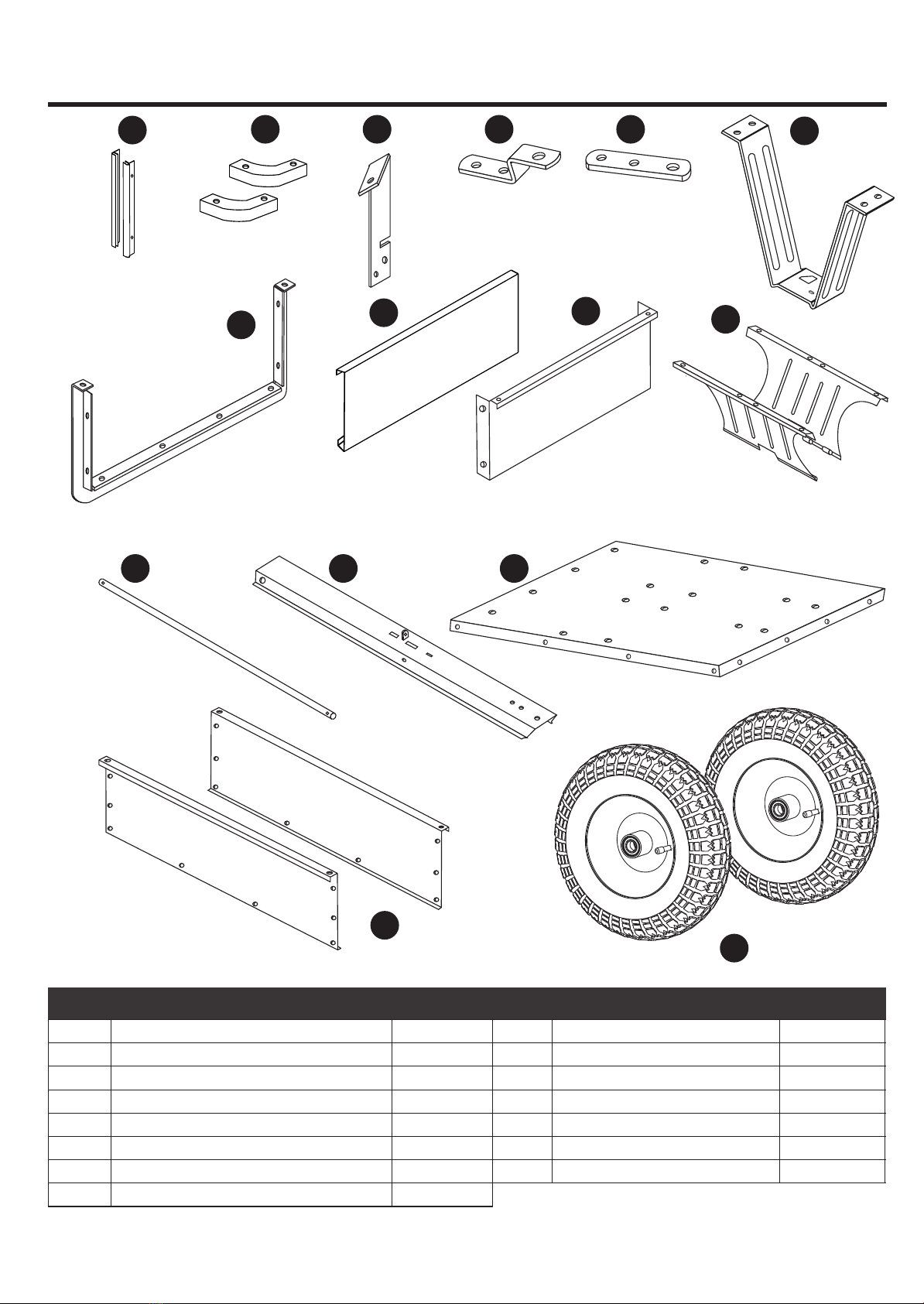
PACKAGE CONTENTS
2
AB C D F
GHIJ
KLM
O
E
N
A
B
C
D
E
I
H
G
F
Tailgate Guides
Corner Caps
Release Pedal
Hitch Bracket
Middle Plate
Tongue Support
Tailgate Reinforcement Bracket
Tailgate
Front Panel
2
2
1
2
1
1
1
1
1
J
K
L
N
M
Wheel Bracket
Axle
Tongue
Bed Panel
Side Panel
2
1
1
1
2
PART DESCRIPTION QUANTITY PART DESCRIPTION QUANTITY
OWheel 2

3
HARDWARE CONTENTS
Ø16 mm Flat Washer
Qty. 4
AA BB
Hitch Pin
Qty. 1
Spacer
Qty. 2
CC
DD
R Clip Pin
Qty. 4 EE Spring Assembly Tool
Qty. 1
FF
Spring
Qty. 1
GG
M8 x 95 mm Screw
Qty. 1
HH
M8 x 30 mm Hex Bolt
Qty. 2
II
M8 x 16 mm Screw
Qty. 12
JJ
M6 x 12 mm Screw
Qty. 30
KK
LL
Ø8 mm Lock Washer
Qty. 14
Ø6 mm Lock Washer
Qty. 30
MM
M8 Hex Nut
Qty. 14
M6 Hex Nut
Qty. 30
NN OO
M8 Lock Nut
Qty. 1
SAFETY INFORMATION
Please read and understand this entire manual before attempting to assemble, operate or install the
product.
WARNING:
PREPARATION
Before beginning assembly of product, make sure all parts are present. Compare parts with package
contents list and hardware contents list. If any part is missing or damaged, do not attempt to assemble
the product.
Estimated Assembly Time: 30 minutes
Tools Required for Assembly (not included): Phillips Screwdriver, 10 mm and 14 mm Wrenches.
Helpful Tools for Assembly (included): Spring Assembly Tool
ASSEMBLY INSTRUCTIONS
Hardware Used
x4
x4
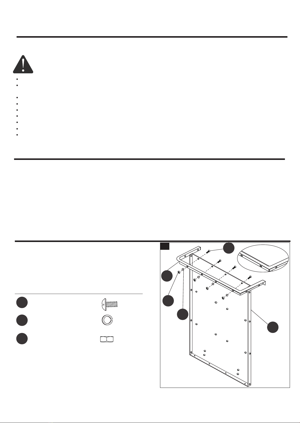
1. Attach the tailgate reinforcement bracket (G) to the
bed panel (M) with four sets of M6 x 12 mm screws
(JJ), Ø6 mm lock washers (LL) and M6 hex nuts
(NN). Do not tighten until STEP 2.
1
LL
NN
JJ
G
M
JJ
LL
NN
M6 x 12 mm Screw
Ø6 mm Lock Washer
M6 Lock Nut
x4
A full capacity load is 400 lbs. evenly distributed over the wheels. DO NOT exceed rated capacity.
NOT recommended to carry full loads on slopes, which can cause loads to shift to one side and
damage wheels or side panels.
Always begin with the transmission in first (low) and gradually increase speed as conditions permit.
Cart only to be used with lawn tractor or ATV.
Cart is NOT for highway use.
DO NOT at anytime carry passengers in this cart. It is not designed to carry passengers.
DO NOT allow children to operate the tractor or the cart attachment.
DO NOT drive too close to a creek or ditch.
DO NOT exceed 10 mph when towing.
4
5
2
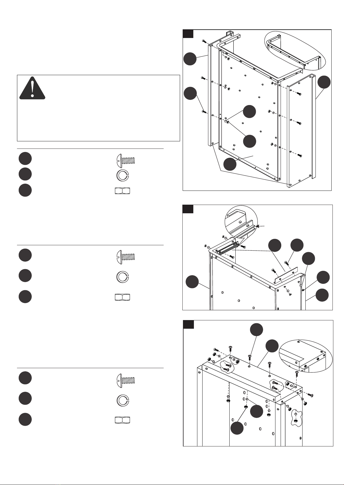
2. Attach the side panels (N) to the bed panel (M) with
six sets of M6 x 12 mm screws (JJ), Ø6 mm lock
washers (LL) and M6 lock nuts (NN). Tighten all
hardware assembled in Steps 1 & 2. Make sure
the bottom holes on both side panels (N) are left
for step 4.
BOTTOM HOLES
LEFT FOR STEP 4
Hardware Used
x6
x6
JJ
LL
NN
M6 x 12 mm Screw
Ø6 mm Lock Washer
M6 Lock Nut
x6
Do not leave the cart unattended in upright position
during assembly. A falling cart can cause personal
injury! Pay close attention to the stability of the cart
while it remains in an upright position. For stability,
assemble on a smooth, level surface.
CAUTION
3. Attach the two tailgate guides (A) with channel facing
downward to the side panels (N) with four sets of
M6 x 12 mm screws (JJ), Ø6 mm lock washers (LL)
and M6 lock nuts (NN). Tighten.
CHANNELS
FACING DOWNWARD
3
N
N
M
JJ
LL
NN
Hardware Used
x4
x4
JJ
LL
NN
M6 x 12 mm Screw
Ø6 mm Lock Washer
M6 Lock Nut
x4
A
N
N
JJ
LL
NN
4. Reverse the cart bed. Attach the front panel (I) to
the cart bed and secure with ten sets of M6 x 12 mm
screws (JJ), Ø6 mm lock washers (LL) and M6 lock
nuts (NN). Tighten.
Hardware Used
x10
x10
JJ
LL
NN
M6 x 12 mm Screw
Ø6 mm Lock Washer
M6 Lock Nut
x10
JJ
LL
NN
I
4

6
5
5. Attach the corner caps (B) to the front ends of cart
bed using four sets of M6 x 12 mm screws (JJ),
Ø6 mm lock washers (LL) and M6 lock nuts (NN).
Then secure the rear ends of cart bed with another
two sets of M6 x 12 mm screws (JJ), Ø6 mm lock
washers (LL) and M6 lock nuts (NN). Tighten all
hardware.
Hardware Used
x6
x6
JJ
LL
NN
M6 x 12 mm Screw
Ø6 mm Lock Washer
M6 Lock Nut
x6
JJ
LL
NN
JJ
NN
LL
B
6. Attach the wheel brackets (J) to the cart bed with
eight sets of M8 x 16 mm screws (II), Ø8 mm lock
washers (KK) and M8 hex nuts (MM). Do not
tighten until STEP 9.
6
Hardware Used
x8
II M8 x 16 mm Screw
JII
MM KK
Hardware Used
x4
x4
II
KK
MM
M8 x 16 mm Screw
Ø mm Lock Washer
M8 Lock Nut
x4
7. Attach the tongue support (F) with spike facing as
shown to the card bed with four sets of M8 x 16 mm
screws (II), Ø8 mm lock washers (KK) and M8 hex
nuts (MM). Tighten.
x8
KK
MM
Ø8 mm Lock Washer
M8 Lock Nut
x8
7
SPIKE FACING
THIS WAY
II
KK
F
MM
7
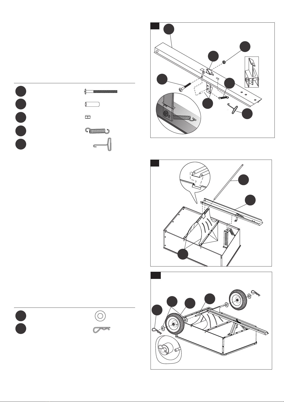
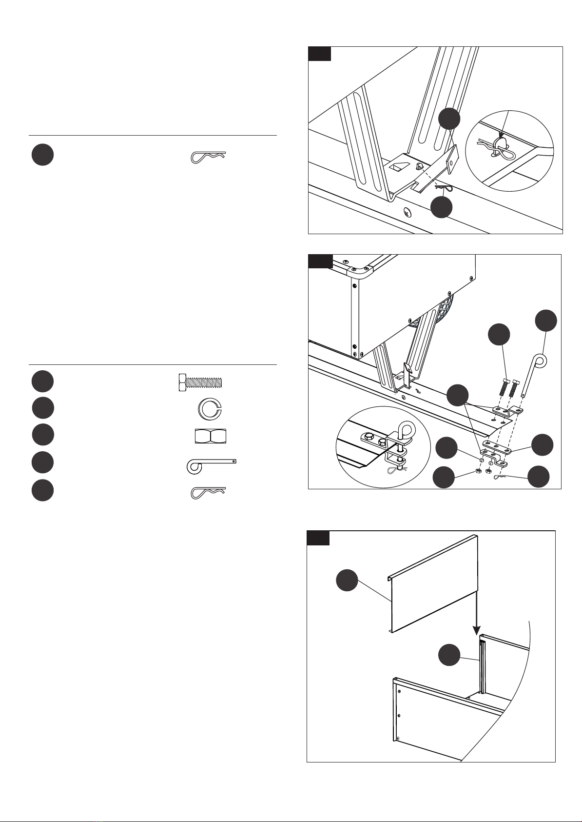
8. Insert the release pedal (C) through the slot on the
tongue (L), thread the M8 x 95 mm bolt (GG) through
the tongue (L), spacer (CC), release pedal (C) and
the other spacer (CC) on each side. Tighten with the
M8 hex lock nut (OO). Then hook the spring (FF) onto
the end hole on the pedal release (C), stretch the
other end of spring (FF) to the hole on the tongue (L)
with the help of spring assembly tool (EE).
8
8
C
L
GG
CC
FF
EE
OO
Hardware Used
x1
x1
GG
CC
FF
M8 x 95 mm Screw
Spring
x2
x1
OO M8 Lock Nut
Spacer
x1
EE Spring Assembly Tool
9. Lay the cart bed down, position the tongue (L) into
the wheel brackets (J). Slide the axle (K) through
the wheel brackets (J) and tongue (L). Tighten the
hardware left from STEP 6.
9
TIGHTEN
K
L
J
10. Attach a wheel (O) (with valve stem facing out) to
the axle (K) with two Ø16 mm flat washers (AA),
then secure with one R clip pin (DD). Repeat for
the other end of axle (K).
10
Hardware Used
x4
AA
DD
Ø16 mm Flat Washer
x2
R Clip Pin
DD
AA OK
8
11.Turn the cart right side up, thread an R clip pin (DD)
through the peg on the tongue to lock to prevent
accidental dumping. Remove the R clip pin (DD)
and step on the release pedal (C) to dump load.
PEG
11
C
DD
Hardware Used
DD x1
R Clip Pin
12. Attach the hitch brackets (D) and middle plate (E)
to the tongue (L) with two sets of M8 x 30 mm hex
bolts (HH), Ø8 mm lock washers (KK) and M8 hex
lock nuts (MM). Tighten. Insert the hitch pin (BB)
into the hitch brackets (D) and middle plate (E),
then secure with an R clip pin (DD).
12
13.Slide the tailgate (H) down through the channels
on the tailgate guides (A).
13
D
E
BB
HH
MM
KK
DD
Hardware Used
x1
x2
HH
BB
M8 x 30 mm Hex Bolt
Hitch Pin
KK Ø8 mm Lock Washer x2
x2
MM M8 Lock Nut
DD x1
R Clip Pin
H
A

9
OPERATING INSTRUCTIONS
USING YOUR UTILITY DUMP CART
1. DO NOT exceed rated capacity of 400 lbs. (182 kg).
2. NEVER tow the dump cart with cart bed raised.
3. ALWAYS secure and lock the utility cart to the vehicle hitch before operating.
4. DO NOT overfill the utility dump cart. Overflow loads can cause the cart and the towing vehicle to
lose traction and skid out of control.
5. ONLY fill the dump cart to a comfortable dumping load. Extremely heavy loads will be difficult to
operate and dump.
6. ALWAYS use the dump cart for its intended purpose.
7. ONLY use approved vehicles when towing the dump cart (lawn/garden tractors and ATVs).
8. ALWAYS make sure that the combined weight of the tow vehicle and the operator ARE GREATER
THAN the load of the cart weight for proper control.
9. DO NOT use cart on public highways or roads.
10. NEVER exceed 10 mph when towing the dump cart.
11. DO NOT make sharp turns that may cause the lawn/garden tractor or ATV tires to rub against the
utility dump cart.
12. ALWAYS slow down before turning.
13. ALWAYS use caution when backing the utility cart. To avoid “jack-knifing” the cart, always back up
in a straight line.
CARE AND MAINTENANCE
On a regular schedule, check that tires are inflated properly. Pressure should be approximately
25 PSI. NEVER over-inflate tires. ALWAYS check rated pressure on each tire.
Use household grease or oil on axle and wheel bearing area regularly or when needed.
Clean and dry off cart after using in wet conditions and before long storage periods. For long storage
periods, it is recommended to cover, keep inside, or store under a covered area.
After each use, clean material out of the cart bed.
Periodically check fasteners for tightness.
Rinse/dry inside and outside of the dump cart after each use.
Annually clean and lightly lubricate parts.
Never exceed load capacity rating of 400 lbs. (182 kg). This will damage the utility dump cart.

10
WARRANTY
Limited 1 year warranty on the dump cart and 2 year warranty on all parts:
1) This product is not intended for commercial use.
2) This warranty applies only to product which has been assembled correctly and operated in
accordance with the instructions contained within this manual. Any alteration, misuse, abuse,
shipping damage, or normal wear and tear on this product is not covered.
3) Excluded from this warranty is normal wear, normal adjustments, and normal maintenance.
This warranty gives you specific rights and you may have other rights that vary from state to state.
REPLACEMENT PARTS LIST
PART DECRIPTION QUANTITY
A
B
C
D
E
F
G
H
I
J
K
L
M
N
O
Tailgate Guides
Corner Caps
Release Pedal
Hitch Bracket
Middle Plate
Tongue Support
Tailgate Reinforcement Bracket
Tailgate
Front Panel
Wheel Bracket
Axle
Tongue
Bed Panel
Side Panel
Wheel
2
2
1
2
1
1
1
1
1
2
1
1
1
2
2
PART DECRIPTION QUANTITY
AA
BB
CC
DD
EE
FF
GG
HH
II
JJ
KK
LL
MM
NN
OO
Ø16 mm Flat Washer
Hitch Pin
Spacer
R Clip Pin
Spring Assembly Tool
Spring
M8 x 95 mm Screw
M8 x 30 mm Hex Bolt
M8 x 16 mm Screw
M6 x 12 mm Screw
Ø8 mm Lock Washer
Ø6 mm Lock Washer
M8 Hex Nut
M6 Hex Nut
M8 Lock Nut
4
1
2
4
1
1
1
2
12
30
14
30
14
30
1
For replacement parts, call our customer service department at 1-877-888-8225, 8 a.m. - 8.p.m.,
EST, Monday - Friday.

11
EXPLODED VIEW
GG
C
H
N
I
B
B
J
F
L
A
G
C
M
N
O
D
E
BB
HH
DD MM
KK
FF CC EE
DD
KK
MM
OO
DD
AA
K
KK
MM
II II
JJ JJ
NN
LL
JJ
JJ
JJ
JJ
NN
LL
LL
NN
JJ
Printed in China
This manual suits for next models
1
Table of contents
Other Blue Hawk Outdoor Cart manuals

Popular Outdoor Cart manuals by other brands


American Cart & Rack
American Cart & Rack 67120 instruction manual

probst
probst VTK-V operating instructions

Enwork
Enwork ZORI MEDIA CART CASTER PLATE Assembly instructions

Storz
Storz UG Series Assembly instructions

HydroSure
HydroSure 100205219 Assembly and operating instructions

Compac
Compac WD500 G1 operating manual


