Storz UG Series User manual

UGxxx Equipment Cart
Assembly Instructions

96206915EN – 10.19 / V1.2
©All product pictures, photos and descriptions and texts are the
intellectual property of KARLSTORZ SE & Co. KG.
Their use for other purposes and reproduction by third parties require
the express approval of KARLSTORZ SE & Co. KG.
All rights reserved.

10.19 / V1.2 1
Equipment Cart
UGxxx
Contents
Section Title Page
0. General information .............................................................................................. 3
Warranty.................................................................................................................. 3
Maintenance and repair .......................................................................................... 4
Reservation of rights............................................................................................... 4
1. Scope of delivery .................................................................................................. 5
2. Assembly................................................................................................................ 9
2.1 Tools and accessories required .............................................................................. 10
2.2 Mounting the basic equipment ............................................................................... 11
2.2.1. Mounting the beams on the base module.............................................................. 11
2.2.2. Mounting the cover................................................................................................. 12
2.2.3. Mounting the drawer/shelves ................................................................................. 12
2.2.4. Connecting the cables ............................................................................................ 13
2.3 Mounting optional accessories............................................................................... 15
2.3.1. Mounting the isolation transformer......................................................................... 15
2.3.2. Mounting the earth leakage monitor....................................................................... 17
2.3.3. Mounting attachments ............................................................................................ 18
2.3.4. Mounting the monitor holding arms ....................................................................... 19
2.4 Component layout of the equipment cart .............................................................. 20
2.5 CO2 bottle holder, universal for small and big bottles ............................................ 21
2.6 Mounting instruction for CO2 twin bottle holder..................................................... 22


10.19 / V1.2 3
Equipment Cart
UGxxx
0. General information
Thank you for your expression of confidence in the KARLSTORZ brand name. Like all of our other
products, this product is the result of years of experience and great care in manufacture. You and your
organization have decided in favor of a modern, high quality piece of equipment from KARLSTORZ.
KARLSTORZ instruments and devices are only intended for use by qualified medical staff who have
been instructed in the use of the product in question. All electrical installations at the place of use must
correspond to local governing ordinances.
Refer servicing to qualified personnel authorized by KARLSTORZ.
Make sure you only ever use genuine spare parts from KARLSTORZ. To determine which spare parts
are required, please consult the attached parts lists. Repair and calibration of this device calls for the use
of special tools and measuring instruments; certain settings inside the device must not be changed.
Please refer to this service manual for further information or contact:
KARLSTORZSE&Co.KG KARLSTORZEndoscopy-America,Inc.
Dr.-Karl-Storz-Straße34,78532Tuttlingen,Germany 2151EastGrandAvenue
POBox230,78503Tuttlingen,Germany ElSegundo,CA90245-5017
Germany USA
Tel.: +49(0)7461708-980 Tel.: 001310338-8100
Fax: +49(0)7461708-75500 001800424218-8526
Web: www.karlstorz.com

4 10.19 / V1.2
Equipment Cart
UGxxx
Maintenance and repair
KARLSTORZ recommends having all equipment checked and inspected once a year by KARLSTORZ
or an authorized representative. All service work such as modifications, repairs, calibrations, and/or
readjustments may only be performed by KARLSTORZ or by an authorized agent.
3WARNING: All repairs and service work should only be carried out by electrotechnically
qualified specialists in accordance with the relevant health & safety and accident prevention
regulations!
2CAUTION: Followingcompletionofthework,performasafetycheckaccordingtoIEC62353!
By making the enclosed technical information available, KARLSTORZ does not authorize any service
or repair by unauthorized service personnel. Any tampering with instruments or devices or unauthorized
servicing or repair work to the device will render the warranty void.
Reservation of rights
This documentation is the sole intellectual property of KARLSTORZ and may not be copied or
transmitted to third parties without the express written approval and consent of KARLSTORZ.
We reserve the right to make engineering modifications in the interest of promoting technological
progress and generating performance improvements without obligation on our part to submit prior notice
thereof.

10.19 / V1.2 5
Equipment Cart
UGxxx
1. Scope of delivery
Basic equipment
Beam package (lateral beams/energy beam)Base module
Drawer unitCover
Assembly setShelf

6 10.19 / V1.2
Equipment Cart
UGxxx
Optional
Earth leakage monitorIsolation transformer
Monitor holding arm, longMonitor holder
Monitor swivel armMonitor holding arm, short
Camera holder for device railCamera holder

10.19 / V1.2 7
Equipment Cart
UGxxx
Bottle stand, smallBottle stand, large
IV Pole, height adjustableIV Pole
Support elementDevice rail
Keyboard trayCable winder


10.19 / V1.2 9
Equipment Cart
UGxxx
2. Assembly
1NOTE: DetailsoftheassemblyoftheCORequipmentcartseriesaswellasthedescriptionofhow
devicesaretobecorrectlypositionedandconnectedonthecartcanalsobefoundintheassembly
video(www.karlstorz.com).

10 10.19 / V1.2
Equipment Cart
UGxxx
2.1 Tools and accessories required
Allen key 5mm (included in scope of supply)
Allen key 4mm (included in scope of supply)
Crosspoint screwdriver, size 2
Cable tie etc. (included in scope of supply)
10.19 / V1.2 11
Equipment Cart
UGxxx
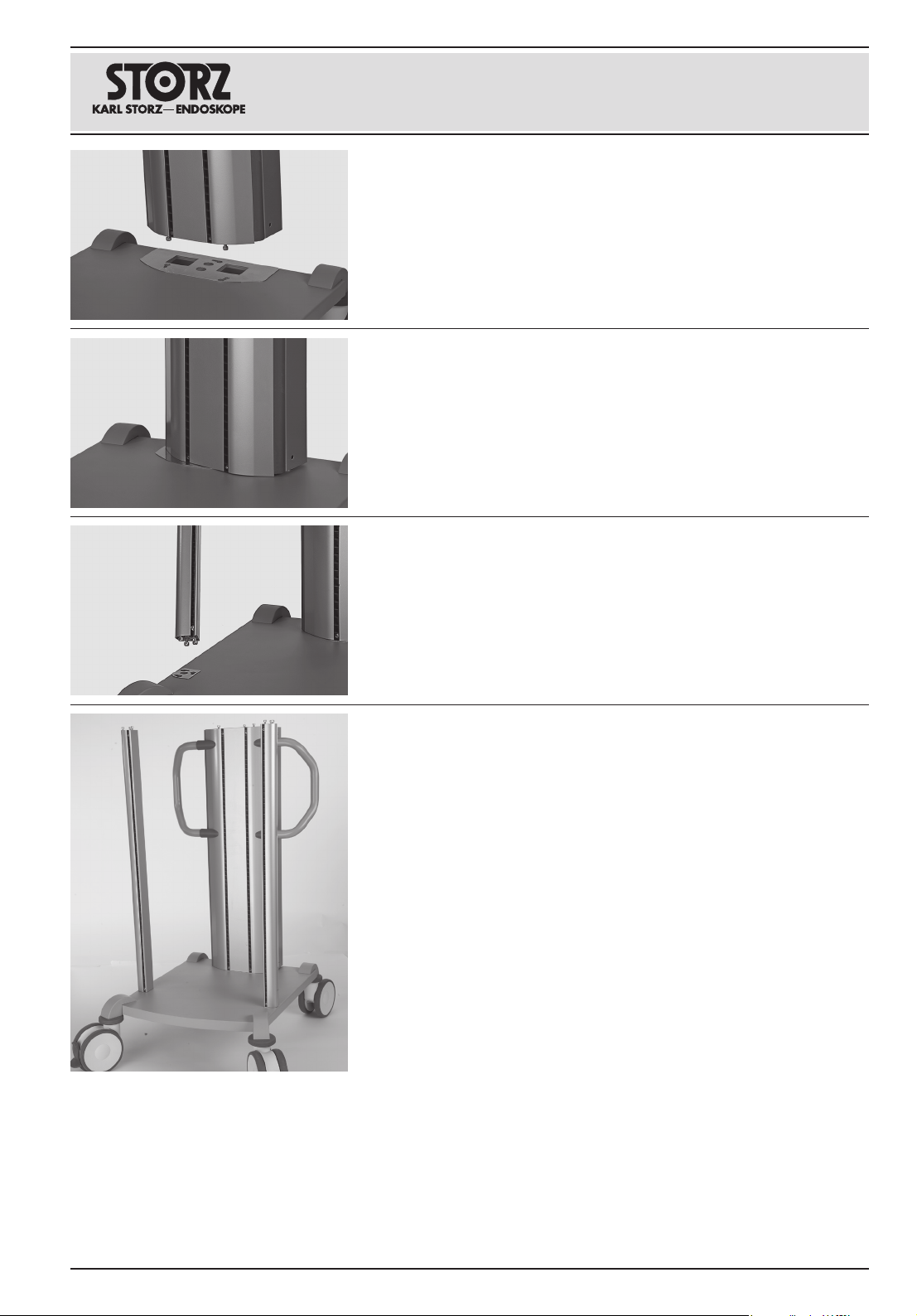
To facilitate assembly, only firmly tighten the screws after mounting the
drawers and shelves.
2.2 Mounting the basic equipment
2.2.1. Mounting the beams on the base module
Place the energy beam on the base plate by positioning the screws in the
larger recesses of the elongated holes.
Turn the beam in position, the screws are guided into the elongated holes
in the process.
Proceed in the same manner when mounting the two lateral beams on
the base plate.

12 10.19 / V1.2
Equipment Cart
UGxxx
Slide the plastic covers over the lateral beams until they lock into place
in the grid bars.
1NOTE: Thegridbarsaredividedintotwocolorsforbetter
orientation.Thecolorofthebarchangeseverytenslotsinorderto
facilitateinstallationoftheshelves/drawers.
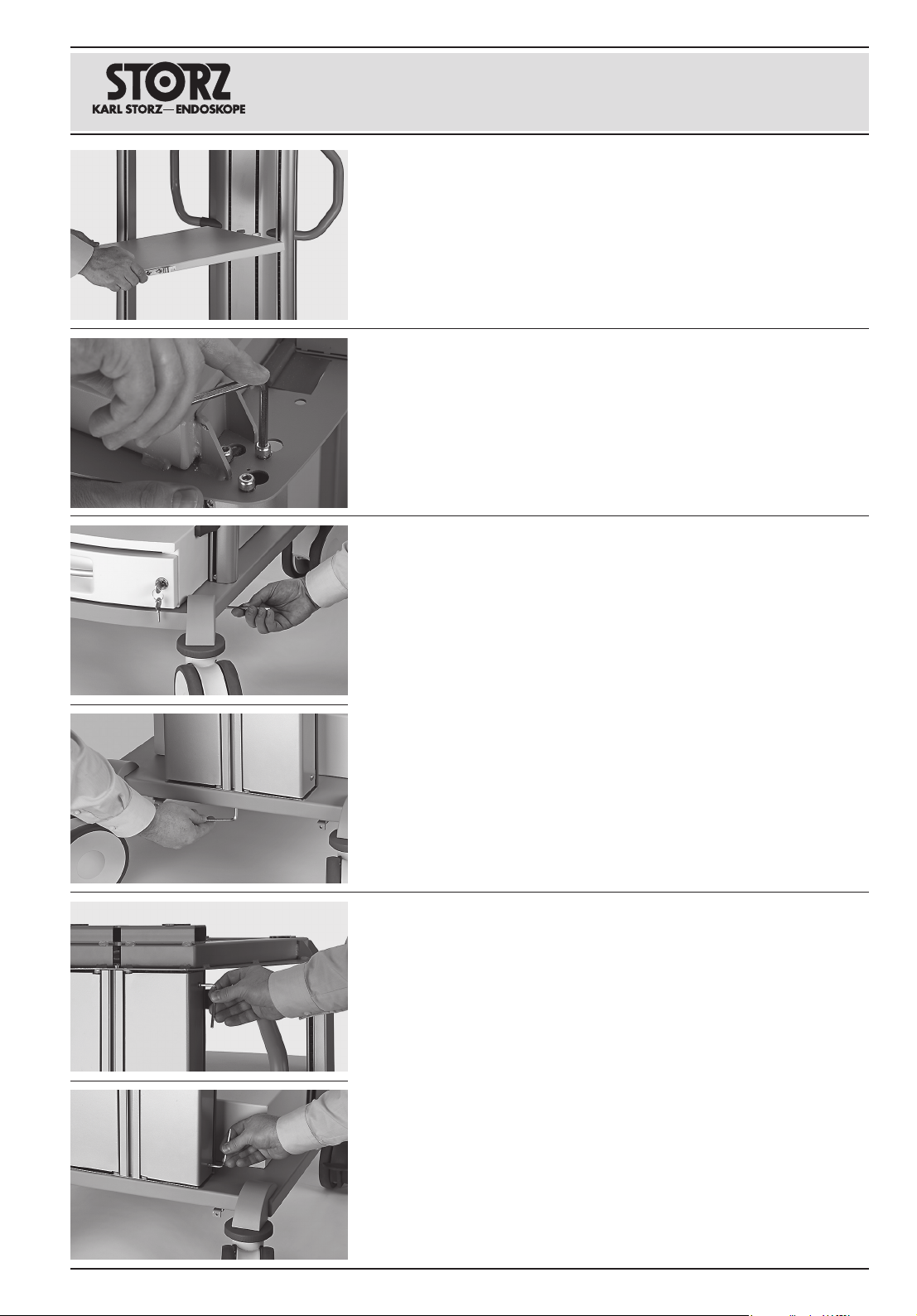
2.2.3. Mounting the drawer/shelves
Place the drawer unit on the base plate and insert the holders from the
rear in the grid bars on the beams.
Push the screws of the beams into position.
2.2.2. Mounting the cover
Place the covers on the uprights by positioning the screws in the larger
recesses of the elongated holes.
10.19 / V1.2 13
Equipment Cart
UGxxx
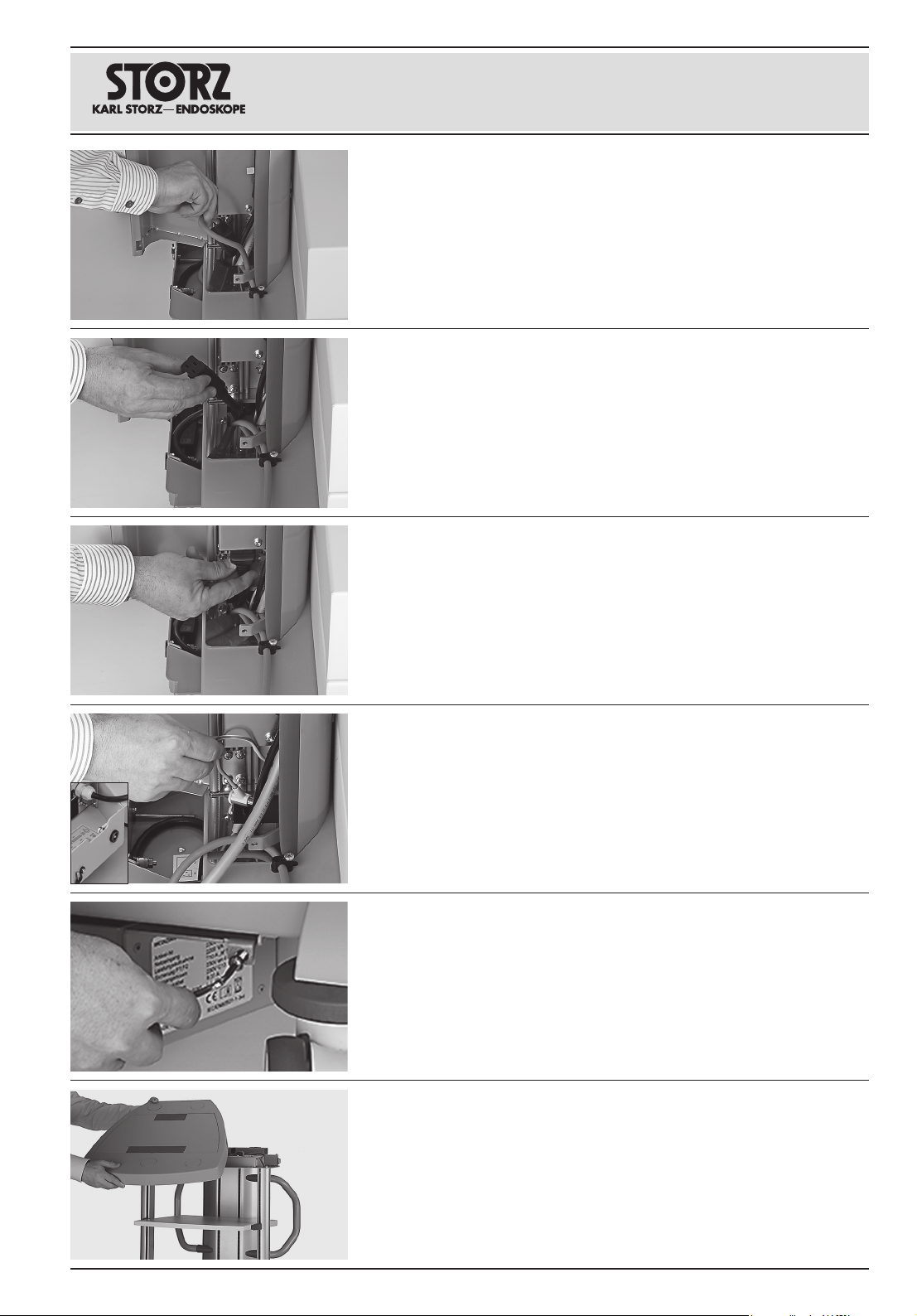
2.2.4. Connecting the cables
Undo the two screws which close the energy beam compartment.
(Allen key 4 mm)
Then firmly tighten the screws which secure the beams on the base
module.
(Allen key 5mm)
Firmly tighten the screws which secure the beams on the cover.
(Allen key 5mm)
Proceed in the same manner when mounting the shelves.

14 10.19 / V1.2
Equipment Cart
UGxxx
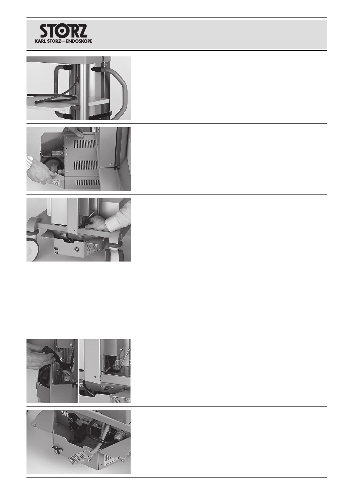
Route the supply line of the equipment cart from below through the
recess in the cover intended for this purpose ...
... in the energy beam.
Connect the cable to the distribution board.
Connect the cable to the external power supply by inserting the power
cord in the distribution board from below.
Attach the strain relief to the power cord.
Route the ground cable from below through the recess on the base
module and connect the cable.
Put the casing on the cover.
Secure the casing on the cover from below with the four screws intended
for this purpose.
(Crosspoint screwdriver, size 2)
1NOTE: Ifyouaremountinganearthleakagemonitor,onlyscrewthe
casingintoplaceafterassembly.
10.19 / V1.2 15
Equipment Cart
UGxxx
Connect the external power supply to the isolation transformer.
Entire power supply via main switch
Undo the cable connections of the external power supply on the
distribution board and instead connect the power cord of the isolation
transformer.
Route the external power supply through the recess to the isolation
transformer.
To control the entire power supply of the equipment cart via the main
switch, connect the cables as follows.
Alternatively, only the socket outlet in the energy beam can be controlled
via the main switch of the equipment cart, so that devices directly
connected to the isolation transformer can still be supplied with power,
see the following chapter.
Mount the cover of the grid bars; cut it to the required length plus 5mm.
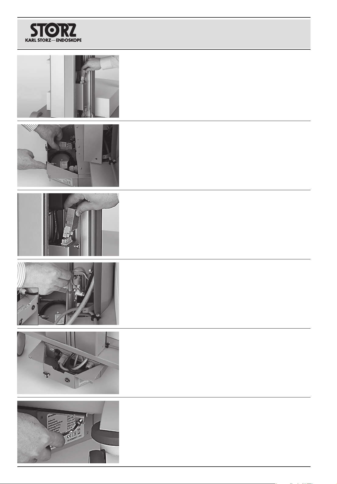
2.3 Mounting optional accessories
2.3.1. Mounting the isolation transformer
Slide the isolation transformer from the rear along the guide rails under
the base plate.
Route the power cord of the isolation transformer from above through the
recess intended for this purpose in the energy beam.
16 10.19 / V1.2
Equipment Cart
UGxxx
Undo the cable connection of the equipment cart supply line on the
distribution board and route the supply line through the recess intended
for this purpose to the isolation transformer.
Remove the bridge on the isolation transformer.
Attach the bridge to the distribution board.
Route the ground cable of the equipment cart from below through the
recess intended for this purpose to the isolation transformer.
Connect the supply line and the ground cable to the isolation transformer.
Secure the isolation transformer on the base module with the two screws
intended for this purpose.
(Allen key 4 mm)
10.19 / V1.2 17
Equipment Cart
UGxxx
2.3.2. Mounting the earth leakage monitor
Remove the casing from the cover.
Secure the isolation transformer on the base module with the two screws
intended for this purpose.
(Allen key 4 mm)
Route the ground cable of the equipment cart from below through the
recess intended for this purpose to the isolation transformer.
Connect the ground cable to the isolation transformer.
...and instead connect the power cord of the isolation transformer.
Undo the cable of the external power supply on the distribution board...
Only power supply socket outlet via main switch
Route the external power supply through the recess to the isolation
transformer.
Connect the external power supply to the isolation transformer.
18 10.19 / V1.2
Equipment Cart
UGxxx
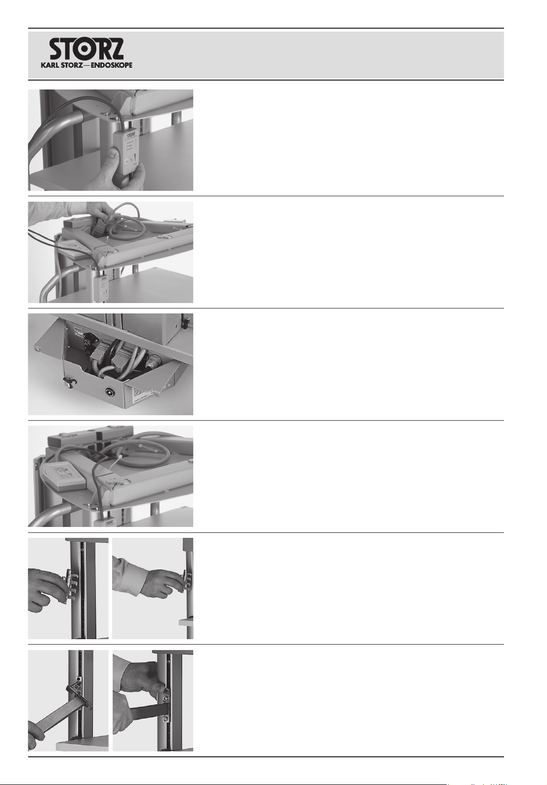
If separate, mount the attachment by inserting the pin into the hole
intended for this purpose and turn the attachment into position.
2.3.3. Mounting attachments
Mount the respective attachment or, if separate, its holder on the lateral
beam by inserting it in the grid bars from the rear and pressing it down
until it locks into place.
Position the earth leakage monitor as shown in the picture so that no
cables are damaged when the attaching the casing.
2CAUTION: Riskofsquashing!Ensurethatnocablesarelocatedin
theguidesforthecasing.
Mount the earth leakage monitor on the lateral beam by inserting the
holder in the grid bars from the rear and pressing it down until it locks
into place.
Route the supply line of the earth leakage monitor from below through
the recess intended for this purpose in the cover through the energy
beam and to the isolation transformer.
Connect the cable to the isolation transformer.
Table of contents
Other Storz Outdoor Cart manuals

Popular Outdoor Cart manuals by other brands

Sunnydaze Decor
Sunnydaze Decor LAM-789 manual

Extreme Tools
Extreme Tools EX3204TC manual

CARTER-HOFFMANN
CARTER-HOFFMANN PH188 Operating, maintenance instructions & Spareparts list

LEGRAND
LEGRAND CHIEF Voyager Series installation instructions

RAWLINK
RAWLINK 36101 instruction manual

HECKLER
HECKLER H720 manual


