Blue Ice T15 User manual

Page 1
Section1 To the installer
Air Cooled Units
The model T15 ice cream machine’s air cooling unit require a minimum of 15.2cm of
clearance around both sides. Install the skirt provided on the right side of the unit and
place the back of the unit against a wall to prevent recirculating of warm air.
Electrical Hook-Up Installation For 50 Hertz, 1 Phase, Supplied With Cord and
Plug
This equipment is supplied with a 3-wire cord and grounding type plug for connection
to a single phase, 50 hertz, branch circuit supply. This unit must be plugged into a
properly grounded receptacle. The cord and plug provided for 230Volts, 50Hertz,
1Phase, is 8 Amp; therefore the wall outlet must also be 8 Amp. Check the data label,
located in the side panel, for electrical specifications. The plug should be accessible
after installation.
If the supply cord is damaged, it must be replaced by the manufacturer, its service
agent or similarly qualified person in order to avoid a hazard.
Permanent wiring may be employed if required by local codes. Instructions for
conversion to permanent wiring are as follows:
1. Be sure the freezer is electrical disconnected.
2. Remove the appropriate panel and locate the small electrical box at the base of
the freezer.
3. Remove the factory-installed cord and strain relief bushing.
4. Route incoming permanent wiring through hole in base pan.
5. Connect two power supply leads. Attach ground (earth) wire to the grounding lug
inside the electrical box.
6. Be sure the unit is properly grounded before applying power.
Electrical Connections for Models Without Cord and Plug Supplied
Each freezer requires one power supply for each data label. Check the data label on
the freezer for fuse, circuit ampacity and electrical specifications refer to the wiring
diagram provided inside of the control box, for proper power connections.
This equipment is intended to be installed in accordance with the National Electrical
Code. The purpose of this code is the practical safeguarding of persons and property
from hazards arising from the use of electricity. This code contains provisions
considered necessary for safety. Compliance therewith and proper maintenance will
result in an installation essentially free from hazard!
CAUTION: THIS EQUIPMENT MUST BE PROPERLY GROUNDED! FAILURE TO
DO SO CAN RESULT IN SEVERE PERSONAL INJURY FROM ELECTRICAL

Page 2
Section2 To the Operator
The freezer you have purchased has been carefully engineered and manufactured to
give you dependable operation.
These units, when properly operated and cared for, will produce a consistent quality
product. Like all mechanical products, they will require cleaning and maintenance.
A minimum amount of care and attention is necessary if operating procedures
outlined in this manual are followed closely.
This Operator’s Manual should be read before operating or performing any
maintenance on your equipment.
The Model T15 will NOT eventually compensate and correct for any errors during the
set-up or filling operations. Thus, the initial assembly and priming procedures are of
extreme importance. It is strongly recommended that personnel responsible for the
equipment’s operation, both assembly and disassembly, go through these
procedures together in order to be properly trained and to make sure that no
misunderstandings exist.
If the supply cord is damaged, it must be replaced by special cord or assembly
available from the manufacturer or its service agent.
MIX INFORMATION
The hygiene ice cream powder is required to be used for frozen production. Mix can
vary considerably from one manufacturer to another. Differences in the type of
ingredients, quality, and quantity all have a different bearing on the finished frozen
product. A change in freezer performance that cannot be explained by a technical
problem may be related to mix. Mix does not improve with age. Old mix or mix that
has been stored at too high a temperature, can result in a finished product that is less
than satisfactory from the appearance and taste standpoint.
Proper serving temperature varies from one manufacturer’s mix to another. Most
mixes should provide a satisfactory product in the –9℃ to –5℃ range. When
checking the temperature, stir the thermometer in the frozen product to read the true
temperature.
Always maintain at least 2cm of mix in the hopper. The maximum of mix in the
hopper is 8liters.
FOR ASSISTANCE PLEASE CONTACT:
Blue Ice Machines Limited
Website: www.blueicecreammachine.co.uk
Email: info@blueicecreammachine.co.uk
Lea Rd Trading Estate,
Lea Rd, Waltham Abbey
EN91 AE WALTHAM ABBEY
United Kingdom
Office: 02088016919 / 442088016919

Page 3
Section3 Safety
Extra caution should be taken when in contact with freezer and parts.We have gone
to extreme efforts to design and manufacture built-in safety features to protect both
you and service technician.
IMPORTANT- Failure to adhere to the following safety precautions may result
in severe personal injury. Failure to comply with these warnings may damage
will result in part replacement expense.
TO OPERATE SAFELY:
1. DO NOT operate the freezer without reading this operator’s manual. Failure to
follow this instruction may result in equipment damage, poor freezer performance,
health hazards, or personal injury.
2. DO NOT operate the freezer unless it is properly grounded. Failure to follow this
instruction may result in electrocution.
3. DO NOT allow untrained personnel to operate this machine. Failure to follow this
instruction may result in severe personal injury to fingers or hands from
hazardous moving parts.
4. DO NOT attempt any repairs unless the main power supply to the freezer has
been disconnected. Failure to follow this instruction may result in electrocution.
Contact your local authorized Distributor for service.
5. DO NOT operate the freezer with larger fuses than specified on the freezer data
label. Failure to follow this instruction may result in electrocution or damage to he
machine. Consult your electrician.
6. DO NOT operate the freezer unless all service panels and access doors are
restrained with screws. Failure to follow this instruction may result in severe
personal injury from hazardous moving parts.
7. DO NOT obstruct air intake and discharge openings:
Minimum of 15.2cm of clearance around both sides. Install the skirt provided on
the right side of the unit and place the back of the unit against a wall to prevent
recirculating of warm air.
8. DO NOT operate the freezer out of the temperature of area 10℃- 40℃.
Failure to follow this instruction may cause poor freezer performance and damage to
the machine.
1. DO NOT put objects or fingers in door spout. Failure to follow this instruction may
result in contaminated product or personal injury from hazardous moving parts.
2. DO NOT remove the dispensing door or beater assembly unless the control
switches are in the “OFF” position. Failure to follow this instruction may result in
severe personal injury from hazardous moving parts.

Page 4
Section4 Operator Parts Identification
Item Description Part No. Item Description Part No.
1 Hopper Cover Assembly T15000030 11 Decal T15000005
2 Standpipe T15000001 12 Hold-Drip Pan T15020301
3 Mix Level Probe T15020430 13 Splash Shield T15000006
4 Top Panel T15020440 14 Drip Tray T15000007
5 Back Panel T15000002 15 Low-Front Panel T15010002
6 Hopper T15020431 16 Panel A-Front T15020301
7 Left Side Panel T15000003 17 Cylinder Evaporator T15020201
8 Drip Pan T15000004 18 Bolt T15020302
9 Leg-Plastic T15010020 19 Indicator Light "Mix Low" T15070203
10 Top-Front Panel T15070101 20 Right Side Panel T15000008
1
2
3
4
5
7
8
6
9
1 0
1 1
1 2
1 3
1 4
1 5
1 6
1 7
1 8
1 9
2 0

Page 5
Section4 Operator Parts Identification
Dispensing Door and Beater Assembly
ITEM Part Number QTY. Description
1 T15020703 1 Seal O-Ring
2 T15020710 1 Beat
3 T15020702 1 Front Bearing
4 T15020501 1 O-Ring
5 T15020610 1 Dispensing Door
6 T15020504 2 O-Ring
7 T15020503 1 Draw Valve
8 T15020505 1 Valve Lifter Arm
9 T15020506 1 O-Ring
10 T15020507 1 Draw Valve Handle
11 T15020508 1 Design Cap
12 T15020509 2 Nut
1
2
3
4
5
6
7
8
9
1
0
1
1
1
2

Page 6
Section5 Important: Operating Control
Before operating the freezer, it is required that the operator knows the function of
each operating control.
Item Description Part No.
1 Power Switch T1507C201
2 Spigot Switch T15070103
3 Mix Refrigeration Switch T1507C201
4 Reset Switch T1507C202
5 Indicator Light- "Mix Low" T1507C203
6 Top-Front Panel T15070101
--------------------------------- The ON Position
--------------------------------- The WASH Position
--------------------------------- The Mix refrigeration Position
--------------------------------- The Standby Position
------------------------------------ The OFF Position
56
1
2
3
4

Page 7
Section5 Important: Operating Control
A. Power Switch
The center position is “OFF”. The left position is “WASH” which activates the beater
motor only (Figure 5-1). The Power switch’s position is “ON” (Figure 5-2) which
activates the beater motor and the refrigeration system.
B. Mix Refrigeration Switch
The Mix refrigeration switch is located under the
left of control panel. For the separate hopper
refrigeration system to operate, the mix
refrigeration switch must be in the “Mix
Refrigeration” position (Figure 5-3). If the
temperature of ice cream mix is under 4℃, the
hopper refrigeration system will stop
automatically. If the temperature of ice cream
mix is over 5℃, the hopper refrigeration system
will start automatically. When the Power and
Mix refrigeration are both in “ON” position, the
separate hopper refrigeration system is also
operation.
C. Standby Position
The Separate Hopper Temperature Retention System
and the Cylinder Evaporator Refrigeration System are
standard features. The Separate Hopper Temperature
Retention System incorporates the use of a separate
small refrigeration system to remain the mix in the
hopper below 5℃ to assure bacteria control.
Place the Power Switch in “ON” position (Figure 5-4),
then place the Mix Refrigeration Switch in “Mix
Refrigeration” position (Figure 5-5), the Separate
Hopper Temperature Retention System and the
Cylinder Evaporator Refrigeration System are
activated. During long “No Sale” period like at night,
please set the Standby function.
Figure 5-1 Figure 5-2
Figure 5-3
Figure 5-4
Figure 5-5

Page 8
Section5 Important: Operating Control
D. Reset Switch
The reset switch is located under the control panel of the machine. When operate the
machine first time after connecting or re-connecting the power, you must push the
reset switch first, and then place the power switch. Otherwise, the power switch is
not available.
If an overload condition occurs, the freezer will automatically stop operating.
Please find the reason of overload and assure resolve the problems correctly. To
properly reset the freezer, place the power switch and the mix refrigeration switch in
the “OFF” position. Wait two or three minutes; then press the push-button switch.
Place the power switch in the “WASH” position and observe the freezer’s
performance; place the power switch and the mix refrigeration switch in the “ON”
position.
E. Indicator Light-”Mix Low”
A mix level indicating light is located at the front of the machine. When the light is on,
it indicates that the mix hopper has a low supply of mix and should be refilled as soon
as possible. Always maintain at least 2cm of mix in the hopper. If you neglect to add
mix, a freeze-up may occur. This will cause eventual damage to the beater assembly
and the compressor.
F. Spigot Switch
Place the power switch in the “ON” position, wait about 15~20 minutes, the ice cream
product is consistent, the freezer will automatically stop operating. The spigot switch
will automatically actuate the motor when the spigot is opened to dispense product.

Page 9
Section6 Operating Procedures
The machine has been selected to illustrate the pictured step-by-step operating
procedures. It has a 1.7liter capacity freezing cylinder. The mix flows by gravity from
the hopper to the freezing cylinder through an air tube. This machine is a counter
model with a single spout door.
We begin our instructions at the point where we enter the store in the morning and
find the parts disassembled and laid out to air dry from the previous night’s cleaning.
These opening procedures will show you how to assemble these parts into the
freezer with fresh mix in preparation to serve your first portion.
Only there is raw material in the mix hopper can you run the machine “Cool”.
You should STOP the machine if there is no raw material in the hopper.
There are close relations between hardness setting up and environment temperature
producing the finished product actually.
Assembly
Note: When lubrication parts, use an approved food grade lubricant.
Step 1 Install the beater assembly.
1. Install the beater seal to the beater (Figure 6-1).
2. Insert the beater assembly through the rear shell bearing at the back of the
freezing cylinder and engage the hex end firmly into the female socket (Figure
6-2). When properly seated, the beater will not protrude beyond the front of the
freezing cylinder. DO NOT LUBRICATE THE HEX END.
Step 2 Assemble the dispensing door (Figure 6-3).
1. Place the o-ring into the grooves on the back
of the dispensing door and lubricate with
lubricant.
2. Slide the front bearing over the baffle rod so
the flanged edge is against the door. Place
the white plastic guide bearing on the end of
the baffle rod.
DO NOT LUBRICATE THE FRONT BEARING OR THE GUIDE BEARING.
Figure 6-1 Figure 6-2
Figure 6-3

Page 10
Section6 Operating Procedures
Step 3 Install the dispensing door (Figure 6-4).
Insert the hand screws into the slots in the
dispensing door. With both hands, hold the
sides of the beater assembly. The white
guide bearings must fit securely in the
holes of the drive shafts. Finger-tighten
the hand screws equally drive shafts.
Finger-tighten the hand screws equally to
insure that the door is snug. Don’t
over-tighten.
Note: The dispensing door is in the correct position when the door spout is on the
bottom.
Step 4 Install the draw valve (Figure 6-5).
Slide the two O-rings into the grooves on
the draw valve and lubricate with lubricant.
Lubricate the inside of the dispensing door
spout from the bottom. Insert the draw
valve into the dispensing door from the
bottom.
Note: The draw valve is installed correctly when the slotted opening in the draw
valve is visible through the ”window” of the dispensing door.
Step 5 Install the draw valve handle
(Figure 6-6).
Insert the valve lifter arm through the slotted
opening in the draw valve and align the
other end with the cross holes of the
dispensing door.
Hint: The valve lifter arm may be aligned with left or right cross hole. The draw
valve handle will be placed through the opposite cross hole of the valve lifter arm.
Slide the o-ring into the groove on the draw valve handle and lubricate with lubricant.
Insert the draw valve handle through the opposite cross hole and into the opening of
the valve lifter arm.
Hint: The draw valve handle can be assembled at varied vertical positions. Choose
an angle which is comfortable for you. The draw valve must be raised completely
when the draw valve handle is down.
Figure 6-4
Figure 6-6
Figure 6-5
Page 11
Section6 Operating Procedures
Step 6 (Figure 6-7)
Snap the design cap over the bottom of the
dispensing door spout.
Step 7 (Figure 6-8)
Lay the air tube in the bottom of the mix
hopper.
Sanitizing
Step 1
Prepare 3.8 liters of an approved 100PPM sanitizing solution. USE WARM WATER
AND FOLLOW THE MANUFACTURER’S SPECIFICATIONS.
Step 2
Pour 3.8 liters of sanitizing solution into the hopper and allow it to flow into the
freezing cylinder.
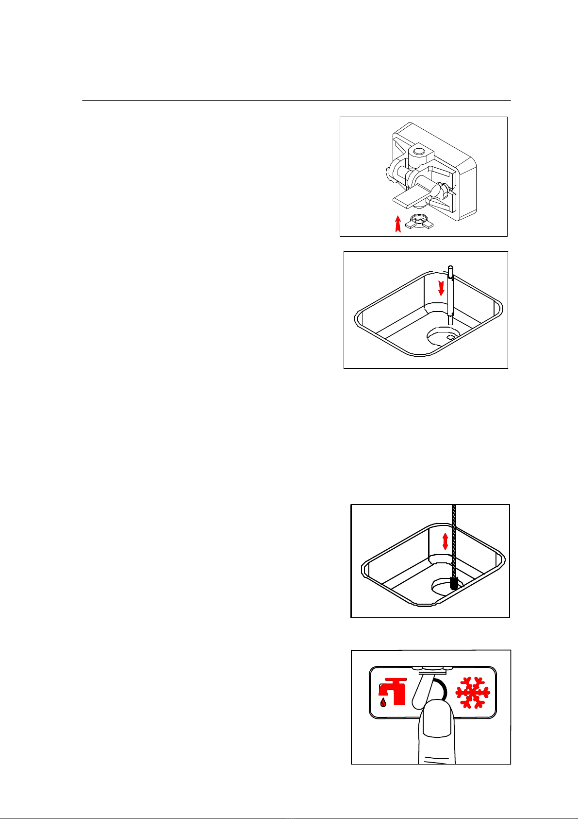
Step 3 (Figure 6-9)
While the solution is flowing into the freezing
cylinder, brush-clean the mix hopper, mix
level stem, mix inlet hole, and air tube.
Step 4
Press the reset switch.
Step 5 (Figure 6-10)
Place the power switch in the “WASH”
position. This will cause the sanitizing
solution in the freezing cylinder to be agitated.
Allow it to agitate for five minutes.
Figure 6-7
Figure 6-8
Figure 6-9
Figure 6-10
Page 12
Section6 Operating Procedures
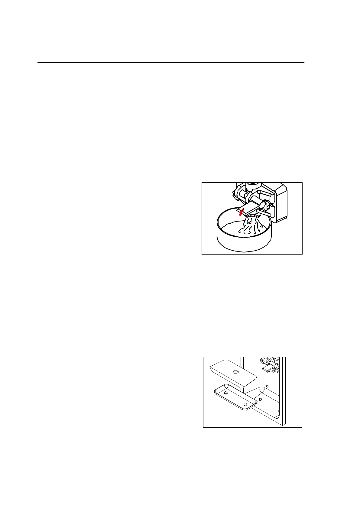
Step 6
Place an empty pail beneath the door spout and raise the draw valve. Draw off all
of the sanitizing solution. When the sanitizer stops flowing from the door spout,
lower the draw valve and place the power switch in the “OFF” position.
Step 7
With sanitized hands, stand the air tube in the corner of the mix hopper.
Priming
Prime the machine as close as possible to the time of first product draw.
Step 1 (Figure 6-11)
With a pail beneath the door spout, raise the
draw valve. Fill the mix hopper with FRESH
mix and allow it to flow into the freezing
cylinder. This will force out any remaining
sanitizing solution. When full strength mix is
flowing from the door spout, lower the draw
valve.
Note: Use only fresh mix when priming the
freeze.
Step 2
When the mix has stopped bubbling down into the freezing cylinder, install the air
tube in the mix inlet hole.
Steps 3 (Figure 5-2, 5-3)
Place the power switch and Mix refrigeration switch in the “ON” position. When the
unit cycles off, the product will be ready to serve.
Step 4
Place the mix hopper cover in position.
Step 5 (Figure 6-12)
Install the front drip tray and splash shield
under the dispensing door.
Step 6
Slide the rear drip into the hole in the side panel.
Figure 6-11
Figure 6-11
Figure 6-12

Page 13
Section6 Operating Procedures
Closing procedure
To disassemble this machine, the following items will be needed:
Two cleaning pails
Sanitized stainless steel rerun can with lid
Necessary brushes
Cleaner
Single service towels
Draining product from the freezing cylinder
Step 1
Place the power switch in the “OFF” position as far ahead of cleaning time as
possible. This will allow frozen product to soften for easier cleaning.
Step 2
Lift the hopper cover. Remove the air tube and mix level float. Take them to the
sink for cleaning.
Step 3
With a sanitized pail beneath the door spout, place the power switch in the “WASH”
position and raise the draw valve. When all the product stops flowing from the door
spout, lower the draw valve and place the power switch in the “OFF” position. If
local health codes permit, empty the rerun into a sanitized stainless steel rerun can.
Cover the container and place it in the walk-in cooler.
Rinsing
Step 1
Pour one 3.8 liters of cool, clean water into the mix hopper. With the brushes,
scrub the mix hopper, the mix level stem and the mix inlet hole.
Step 2
With a pail beneath the door spout, place the power switch in the “WASH” position
and raise the draw valve. Drain all the rinse water stops flowing from the freezing
cylinder. When the rinse water stops flowing from the door spout, lower the draw
valve and place the power switch in the “OFF” position.
Repeat this procedure until the rinse water being drawn from the freezing cylinder is
clear.

Page 14
Section6 Operating Procedures
Cleaning
Step1
Prepare 3.8 liters of an approved cleaning solution. USE WARM WATER AND
FOLLOW THE MANUFACTURE’S SPECIFICATIONS..
Step 2
Pour the 3.8 liters of cleaning solution to the mix hopper and allow it to flow into the
flow into the freezing cylinder.
Step 3
While the solution is following into the freezing cylinder, brush-clean the mix hopper,
mix level stem and mix inlet hole.
Step 4
Place the power switch in the “WASH” position. This will cause the cleaning solution
in the freezing cylinder to agitate.
Step 5
Place an empty pail beneath the door spout and raise the draw valve. Draw off all
the cleaning solution.
When the solution stops flowing from the door spout, lower the draw valve and place
the power switch in the “OFF” position.
Disassembly
Step 1
BE SURE THE POWER SWITCH IS IN THE “OFF” POSITION.
Step 2
Remove the hand screws and the dispensing door. Remove the beater assembly
from the freezing cylinders and take these parts to the sink for cleaning.
Step 3
Remove the front drip tray and the splash shield from the freezer. Take them to the
sink for cleaning.
Brush cleaning
Step 1
Prepare a sink with an approved cleaning solution. USE WARM WATER AND
FOLLOW THE MANUFACTURER’S SPECIFICATIONS.

Page 15
Section6 Operating Procedures
IMPORTANT: Follow label directions, as too STRONG of a solution can cause parts
damage, while too MILD of a solution will not provide adequate cleaning. Make
sure all brushes are available for brush cleaning.
Step 2
Remove the O-rings from the drive shaft of the beater assembly.
Note: To remove the O-ring, use a single service towel to grasp the O-ring. Apply
pressure in an upward direction until the O-ring pops out of its groove. With the
other hand, push the top of the O-ring forward, and it will roll out of the groove and
can be easily removed. If there is more than one O-ring to be removed, always
remove the rear O-ring first. This will allow the O-ring to slide over the forward rings
without falling into the open grooves.
Step 3
From the dispensing door, remove the design cap, draw valve handle, valve lifter arm,
and draw valve. Remove all O-rings.
Step 4
Remove the large O-rings and front bearing from the back of the dispensing door.
Step 5
Return to the freezer with a small amount of cleaning solution. With the black bristle
brush, brush clean the rear shell bearing at the back of the freezing cylinder.
Step 6
Remove the rear drip pan from the side panel and take it to the sink for cleaning.
Note: If the drip pan is filled with an excessive amount of mix, this is an indication that
the drive shaft O-ring of the beater assembly should be replaced or properly
lubricated.
Step 7
Thoroughly brush clean all disassembled parts in the cleaning solution. Make sure
all lubricant and mix film is removed. Take particular care to brush clean the draw
valve core in the dispensing door. Place all the cleaned parts on a clean, dry
surface to air dry overnight.
Step 8
Wipe clean all exterior surfaces of the freezer.
Page 16
1 2 3 4 5 6
O N
Section7 Important: Operating Checklist
Product hardness adjustment
Step 1
BE SURE THE POWER SWITCH IS IN THE “OFF” POSITION.
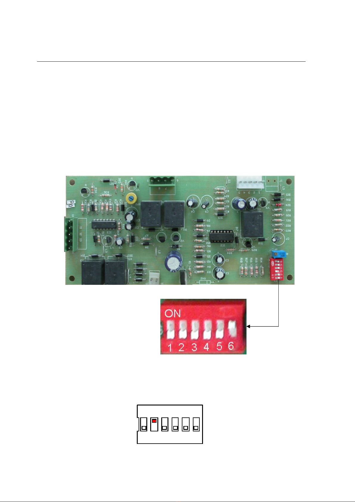
Step 2
The hardness adjustment switch is located under the decorative panel. Remove the
decorative panel, find a P. C. board. On the left-top side of P. C. board, find a
6-position switch.
P.C. Board
6-Position Switch
Step 3
The hardest level is switch 1 “ON” and the softest level is switch 6 “ON”. Adjust the
hardness of ice cream product, change the 6-position switch setting.
HARDER SOFTER
DIP SWITCH “2” IS ON

Page 17
Section7 Important: Operating Checklist
During cleaning and sanitizing
Cleaning and sanitizing schedules are governed by your State or local regulatory
agencies and must be followed accordingly. The following check points should be
stressed during the cleaning and sanitizing operations.
WE RECOMMEND DAILY CLEANING AND SANITIZING.
Troubleshooting Bacterial Count
1. Thoroughly clean and sanitize the machine regularly, including complete
disassembly and brush cleaning.
2. Use all brushes for thorough cleaning. The brushes are specially designed to
reach all mix passageways.
3. Use the smaller, white bristle brush to clean the mix inlet hole which extends from
the mix hopper down to the rear of the freezing cylinder.
4. Use the black bristle brush to thoroughly clean the rear of the freezing cylinder.
Be sure to have a generous amount of cleaning solution on the brush.
5. IF LOCAL HEALTH CODES PERMIT THE USE OF RERUN, make sure the mix
rerun is stored in a sanitized, covered stainless steel container and is used the
following day. DO NOT prime the machine with rerun. When using rerun, skim off
the foam and discard. Mix the rerun with fresh mix in a ratio of 50/50 during the
day’s operation.
6. On a designated day of the week, run the mix as low as feasible and discard after
closing. This will break the rerun cycle and reduce the possibility of high bacteria
and coliform counts.
7. Properly prepare the cleaning and sanitizing solutions. Read and follow label
directions carefully. Too strong of a solution may damage the parts and to weak of
a solution will not do an adequate job of cleaning or sanitizing.
8. The temperature of the mix in the hopper and cooler should be below 4.4℃.

Page 18
Section7 Important: Operating Checklist
Regular Maintenance Checks
1. Check the rear shell bearing for signs of wear (excessive mix leakage in rear drip
pan) and be certain it is properly cleaned.
2. Check the rear shell bearing for signs of wear (excessive mix leakage in rear drip
pan) and be certain it is properly cleaned.
3. Using a screwdriver and cloth towel, keep the rear shell bearing and the female
hex drive socket clean and free of lubricant and mix deposits.
4. Dispose of O-rings or seals if they are worn, torn, or fit too loosely, and replace
with new ones.
5. If an overload condition occurs frequently, maybe the belt is worn, torn, or fit too
loosely. Dispose of the belt and replace with new ones.
6. Follow all lubricating procedures as outlined in ASSEMBLY.
7. This machine is air cooled, check the condenser for an accumulation of dirt and
lint. A dirty condenser will reduce the efficiency and capacity of the machine.
Condensers should be cleaned monthly with a soft brush. Never use screwdrivers
or other metal probes to clean between the fins. Failure to comply may result in
electrocution.
8. This machine is equipped with an auxiliary refrigeration system, check the
auxiliary condenser will reduce the refrigeration capacity of the mix hopper.
Condensers must be cleaned monthly with a soft brush. Never use screwdrivers
or other metal probes to clean between the fins. Failure to comply may result in
electrocution.

Page 19
Section8 Troubleshooting Guide
PROBLEM PROBABLE CAUSE REMEDY PAGE
REF.
1.
No product
being
dispensed
a. The power switch is in the
“OFF” position.
b. The mix level is
inadequate in the mix
hopper.
c. The beater motor
overload.
d. The unit is unplugged at
the wall receptacle.
e. The circuit breaker is
tripped or the fuse is
blown.
f. The dispensing door is
incorrectly assembly.
g. Product is being drawn off
in excess of freezer’s
capacity.
a. Place the power switch
and mix ref. swithc in
the “ON” position
b. Fill the mix hopper with
mix.
c. Reset the freezer.
d. Plug in the power cord.
Press the reset switch.
e. Place the circuit breaker
in the “ON” position, or
replace the fuse. Press
the reset switch.
f. See “Operating
Procedures” for proper
installation.
g. Stop drawing product
and allow the unit to
recover.
7
8
1
8
1
9
13
2.
The machine
will not
operate in the
“ON” mode.
a. The unit is unplugged.
b. The circuit breaker is
tripped or the fuse is
blown.
c. The beater motor
overload, causing a loss
of power to the power
switch.
a. Plug in the power cord;
press the reset switch.
b. Place the circuit
breaker in the “ON”
position, or replace the
fuse. Press the reset
switch.
c. Reset the freezer.
1
1
8
3.
The product
is too hard
a. The 6-position switch is
set too hard.
a. Adjust the 6-position
switch softer.
16
4.
The product
is too soft
a. The 6-position switch is
set too soft.
a. Adjust the 6-position
switch harder.
16

Page 20
PROBLEM PROBABLE CAUSE REMEDY PAGE
REF.
5.
The freezing
cylinder walls
are scored.
a. Operating freezer
without the front bearing
on the dispensing door.
b. The gear unit or the
direct drive is out of
alignment.
a. Install the front bearing
on the dispensing door.
b. Contact service
technician.
9
6.
Excessive
leakage in
rear drip pan.
a. A worn or defective
O-ring are on the beater
drive shaft.
b. The rear shell bearing is
worn.
c. Incorrect lubricant was
used.
d. Inadequate lubricant of
beater drive shaft.
a. Replace the O-rings
every 3 months.
b. Contact service
technician.
c. Use food lubricant.
d. Lubricate the beater
drive shaft properly.
9
9
7.
The draw
valve is
leaking.
a. Incorrect lubricant was
used.
b. A worn or defective
O-ring are on the draw
valve.
c. Inadequate lubricant of
draw valve.
a. Use food lubricant.
b. Replace the O-rings
every 3 months.
c. Lubricate the draw
valve shaft properly.
9
9
9
8.
Product is not
feeding into
the freezing
cylinder.
a. The mix level is
inadequate in the mix
hopper.
b. The mix inlet hole is
frozen.
a. Fill the mix hopper with
mix.
b. Contact service
technician.
13
9.
The unit goes
out on
overload
excessively.
a. There are too many
appliances plugged into
the circuit.
b. An extension cord has
been placed between the
power cord and the wall
receptacle.
a. A separate 10 Amp.
circuit is needed for the
freezer to operate
properly.
b. If the extension cord is
used, it must match the
power cord in size of
circuit ampacity.
1
1
Table of contents


