DroneBeacon db122fpv manual - version 1.1 April2023 - © BlueMark Innovations BV 2023
attached GNSS receiver. So you can use for both the GPS IN and OUT ports the same cables as you
would use to connect the GNSS receiver to the flight controller.
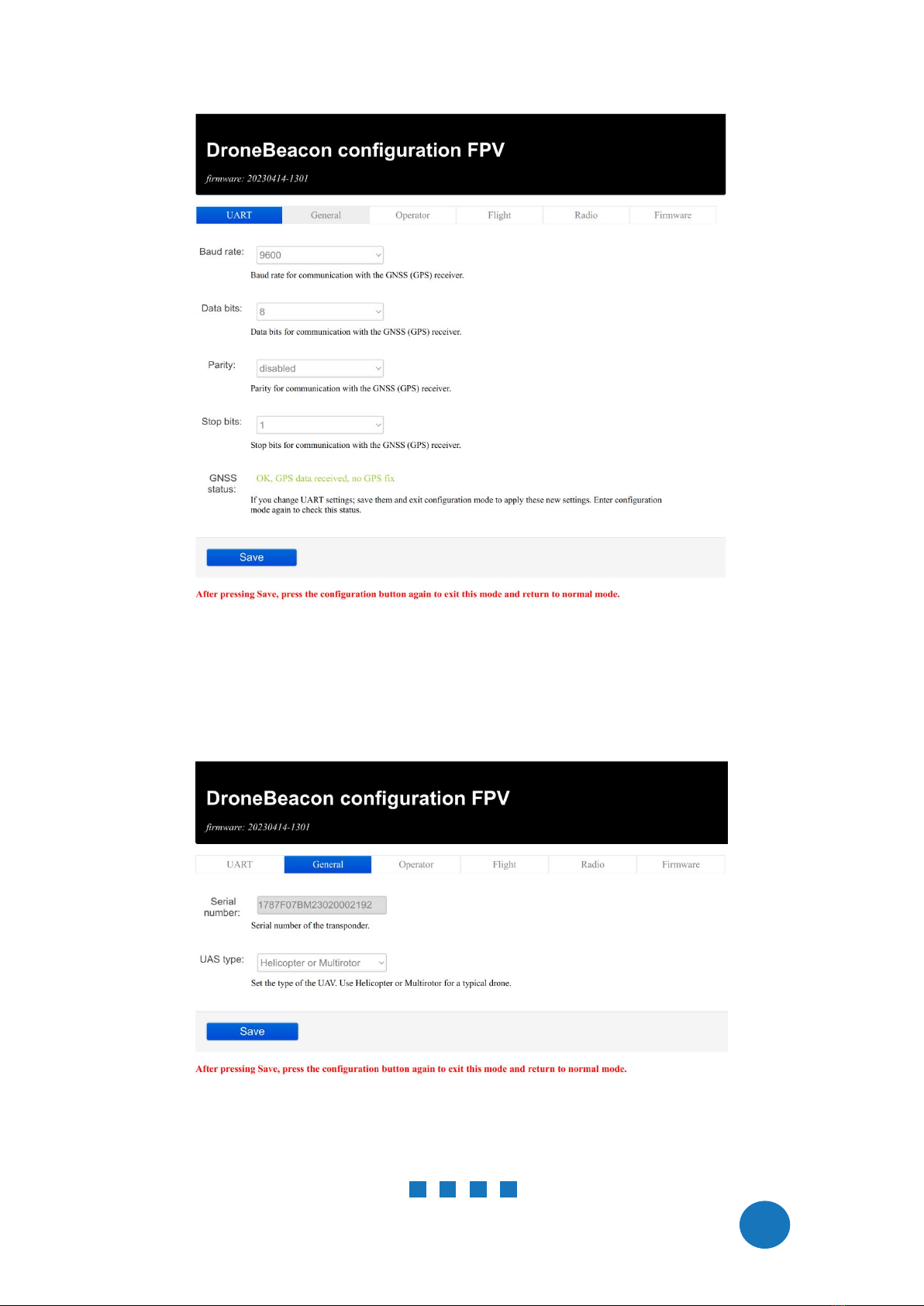
GNSS configuration
The db122fpv reads the GPS signals of the GNSS receiver attached to GPN in port. This information
is used for Remote ID signals. The received GPS signals also relayed to the GPS OUT port. Chapter 2
(section 2.1) describes how you can configure the UART settings of the
GPS IN/OUT
port.
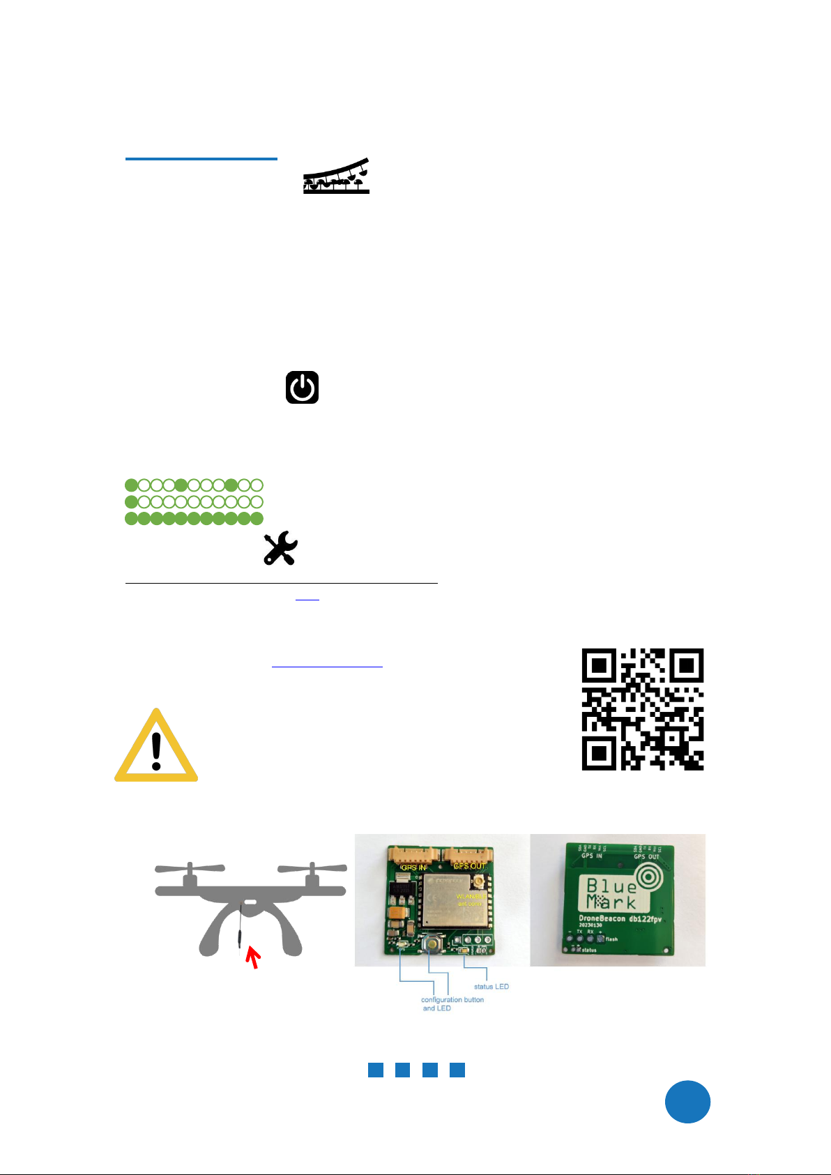
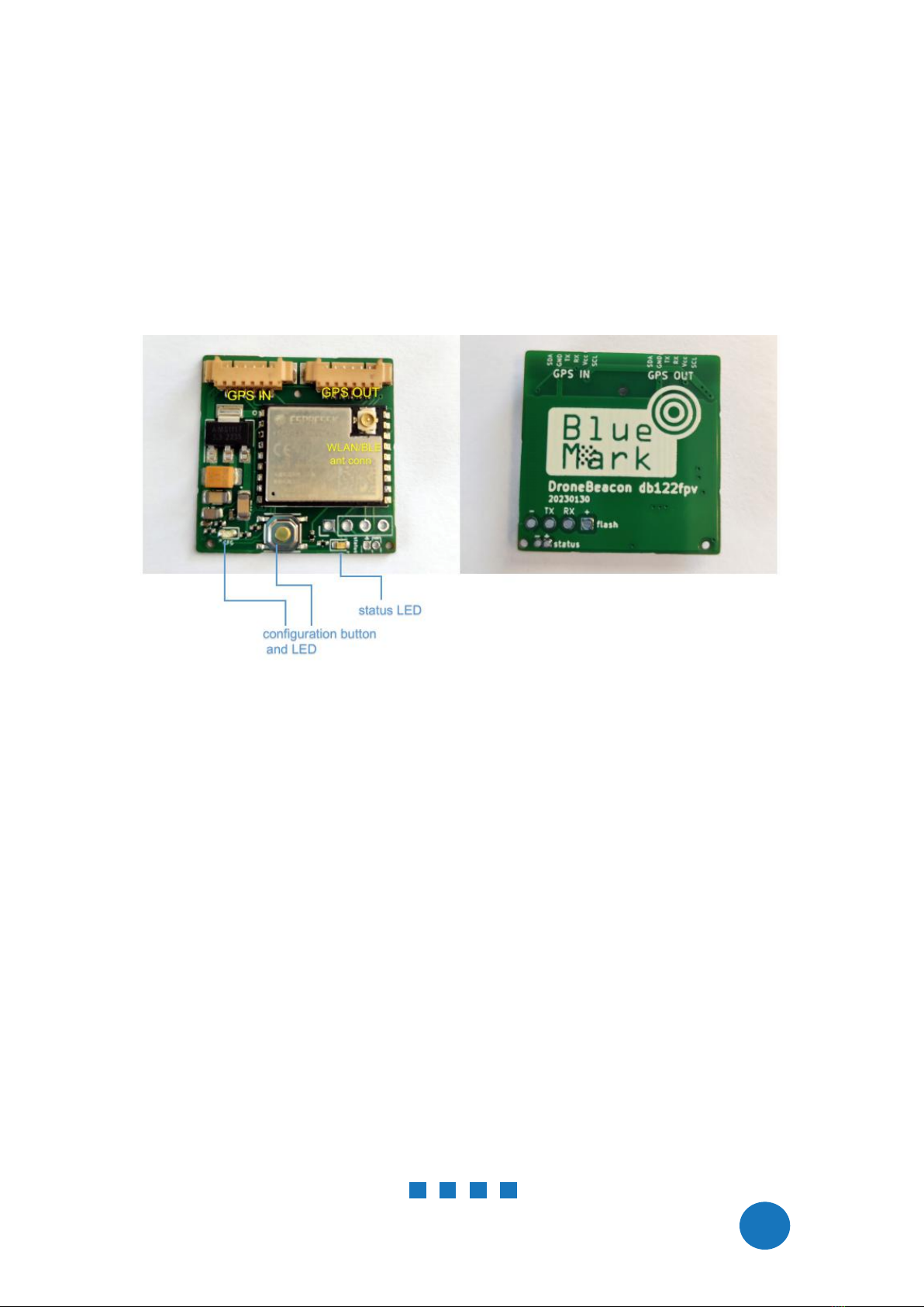
status led
The status led should be visible by the user. And the user can only take-off if the status LED signals
ready to take-off. If the status LED is not visible, it will void the FAA DoC status of the db122fpv
product!
1.5 Using the transponder
Wait for the status LED to signal ready for take off/GPS fix (slowly flashing battery LEDs every 4
seconds).
You are ready to fly.
Status LED
The status LED can have the following states:
-Ready for take-off: slowly flashing (every 4 s), location acquired.
- Non-compliant config: very slow flashing (every 20s), location acquired
- Acquiring location
Note:
For typical use in the USA no configuration is required. USA: use the db122fpv S/N number for
registering your drone at the FAA.
For the EU, you need to enter your operator ID.
A non-compliant configuration can be caused by selecting a non-compliant transmission
protocol, selecting a lower transmit power (for WLAN modes) or selecting a different channel
for WLAN modes than the default channel 6.
Flying a drone could create risks for people, air traffic and other assets. Before
flying, the drone operator has to make sure to know the local rules regarding
drone flights and obtain the necessary authorization to fly the drone(s).
1.6 EMC test
To verify that the db122fpv does not produce interference to the drone or receives interference
from the drone, it is advised to do a quick EMC test. (Only when attached for the first time to a
drone.)
Power on the drone and remote control. Keep the db122fpv powered off.
Verify that the drone, remote control and wireless link are functioning properly.
Power off the drone and remote control.
Power on the db122fpv (using a different power source). Keep the drone and remote control
powered off.
Verify that the db122fpv is functioning properly. For instance by using the Android in Section
1.7 or by looking at the status LED (ready for take-off state).