Blue Mark DroneBeacon 121 Series User manual

DroneBeacon db121/db121pcb manual - version 1.1 April 2023 - © BlueMark Innovations BV 2023
1/19
DroneBeacon - Transponder Manual
121-series
April 2023 - version 1.1

DroneBeacon db121/db121pcb manual - version 1.1 April 2023 - © BlueMark Innovations BV 2023
2/19
The latest version of this manual is located here:
https://download.bluemark.io/db121.pdf
Intended audience: users of the db121/db121pcb transponder
Disclaimer: we are not responsible or liable for errors or incomplete information in this
document.
Version history
version
date
description
1.0
January 2023
Initial release
1.1
April 2023
Updated documentation to be in line with newest
firmware
Improved quick start

DroneBeacon db121/db121pcb manual - version 1.1 April 2023 - © BlueMark Innovations BV 2023
3/19
QUICK START
Attach to the drone
db121
For optimal performance attach the db121 on the top of your drone/airframe:
Use the 3M dual lock™ stickers (included).
clean the surface and remove the foil of the 3M dual lock sticker, apply firm pressure and wait
1 hour for optimal adhesion. Use a sticker for both the db121 and drone. Snap the db121 to
the counter part sticker on the drone. The stickers allow you to easy remove or attach the
db121.
Or/and use two M5 screws.
the db121 has two M5 screw noses that can be used for attaching the db121 to your drone.
connect power (5 - 14V) to the power connector (JST-GH 1.25mm 2-pin)
db121pcb
install the db121pcb to the drone chassis using 4x M2 screws or cable ties
Install the antenna vertical to make sure the antenna pattern is omni-directional and the Remote
ID signals can be received from each direction. Also make sure that the last part of the antenna
(where it gets thicker) is not obstructed by metal objects that could block radio reception in
that direction.
Install the GPS antenna to a location not near metal objects or ground planes. For optimal
performance install the GPS antenna in the horizontal plane.
connect power (5 - 14V) to the db121pcb using the 2-pin power connector (JST-GH 1.25mm
2-pin) or use the (non-populated) auxiliary 2.54mm 2-pin header.
Use the db121/db121pcb
If you power on the drone, the db121/db121pcb will be automatically powered on too.
Wait for a GPS fix (slowly flashing status LED every 4 seconds). You are ready to fly.
Status LED
-Ready for take-off: slowly flashing (every 4 s), location acquired.
- Non-compliant config: very slow flashing (every 20 s), location acquired
- Acquiring location
e
e
l
e
e
l
e
e
e
e
l
e
e
l
e
e
e
e
l
e
e
l
e
e
db121/db121pcb Vertical antenna
installation. Thick antenna part
should not be obstructed by
metal objects

DroneBeacon db121/db121pcb manual - version 1.1 April 2023 - © BlueMark Innovations BV 2023
4/19
Configuration
For typical use in the USA no configuration is required. USA: use the db121/db121pcb S/N number
for registering your drone at the FAA. For the EU, you need to enter your operator ID.
After the db121/db121pcbis powered, press the configuration button. The
red
config LED is now
solid red.
Connect to the
dronebeacon
WLAN network (no password needed)
Point your browser to http://192.168.50.1 or scan the QR code.
Flying a drone could create risks for people, air traffic
and other assets. Before flying, the drone operator has
to make sure to know the local rules regarding drone
flights and obtain the necessary authorization to fly
the drone(s).
configuration web-page

DroneBeacon db121/db121pcb manual - version 1.1 April 2023 - © BlueMark Innovations BV 2023
5/19
Contents
Quick start......................................................................................................................................................................................3
1 Introduction .............................................................................................................................................................................. 6
1.1 Audience.......................................................................................................................................................................6
1.2 Specifications ..............................................................................................................................................................6
1.3 What's in the Box.......................................................................................................................................................7
1.4 Installation....................................................................................................................................................................8
1.5 Using the db121/db121pcb ..................................................................................................................................9
1.6 EMC test.........................................................................................................................................................................9
1.7 Android/iOS app ..................................................................................................................................................... 10
1.8 Open Drone ID.........................................................................................................................................................10
2 Configuration .........................................................................................................................................................................11
2.1 General........................................................................................................................................................................11
2.2 Operator ..................................................................................................................................................................... 11
2.3 Flight............................................................................................................................................................................ 12
2.4 Radio............................................................................................................................................................................ 13
2.5 Firmware.....................................................................................................................................................................14
3 Current profile ....................................................................................................................................................................... 16
4 Troubleshooting ................................................................................................................................................................... 17
5 Warranty ...................................................................................................................................................................................18
6 More information................................................................................................................................................................. 19

DroneBeacon db121/db121pcb manual - version 1.1 April 2023 - © BlueMark Innovations BV 2023
6/19
1 INTRODUCTION
Thank you for purchasing and using DroneBeacon products!
The latest version of this user manual may be downloaded at the following link:
https://download.bluemark.io/db121.pdf
(Direct/Broadcast) Remote Identification (Remote ID) adds “beacon” capability to drones to
broadcast basic information of airborne drones, such as the operator's registration number, drone
serial number and current position. The EU and USA have new rules that make Remote ID
mandatory for drones over 250 grams weight. The beacon information can be used by general
public, law enforcement and drones to give better situation awareness of the airspace around them.
BlueMark Innovations BV offers Remote ID transponders and receivers. DroneBeacon
db121/db121pcb is an add-on (transponder) for drones that broadcasts Remote ID beacon signals.
We also provide other Remote ID add-ons. DroneScout is a receiver that detects Remote ID signals
of nearby drones up to several km distance (in open space). See https://dronescout.co for more
information about our products..
1.1 Audience
This document is intended for users that want to use the
DroneBeacon db121 or db121pcb
transponder as a stand-alone Remote ID add-on for their drone or other UAV product. There is a
separate manual for the
DroneBeacon MAVLink
db201 transponder (intended for drone
manufacturers). Also, we provide a stand-alone Remote ID add-on with battery: the db120
transponder.
1.2 Specifications
The transponder consists of an embedded system and several radio-interfaces to broadcast Remote
ID signals.
Key specifications:
Compliant with international regulations
EU ASD-STAN DIN EN 4709-002
USA ASTM Remote ID Standard ASTM F3411-22a-RID-B/ F3586-22
Accepted by the FAA
db121 https://uasdoc.faa.gov/listDocs/RID000000088
db121pcb https://uasdoc.faa.gov/listDocs/RID000000089
Supports all Remote ID transmission protocols:
BLE legacy
BLE long range
WLAN NaN 2.4 GHz
WLAN Beacon 2.4 GHz
Long range up to 5 km detection range1
1The detection range depends on several factors such as the receiver antenna gain, transmission protocol,
weather conditions, flying height, receiver height line of sight etc. With professional receivers a range up to 5
km is possible. See the DroneScout manual for more details.

DroneBeacon db121/db121pcb manual - version 1.1 April 2023 - © BlueMark Innovations BV 2023
7/19
Omni-directional antenna with 0 (db121) or 3 dBi (db121pcb) gain. Note that a higher
theoretical
antenna gain does not necessary mean a larger detection range in real life.
Transmit power: +18 dBm (WLAN and Bluetooth)
Power
2-pin power connector (JST-GH 1.25mm 2-pin)
or use the (non-populated) auxiliary 2.54mm 2-pin header (db121pcb only)
Input voltage range: 4.5 to 15 V
Positioning
GPS and BDS: 2.5m positioning precision
Suited for outdoor operation (only db121):
IP43 rating
for operation in rainy conditions, the transponder needs to be protected against water.
Dimensions (l x w x h):
db121: 36 x 38 x 28 mm.
with screw nodes the dimensions are 36 x 55 x 28 mm
db121pcb: 33 x 35 x 5 mm.
Operating temperature
-5°C to +40°C
Weight:
11 g (db121)
5 g (db121pcb, including antennas)
Figure 1 - DroneBeacon db121 (left) and db121pcb (right) transponders
1.3 What's in the Box
The following package contents should be present:
1x db121 or db12pcb transponder
db121: 3x 3M dual-lock stickers (1 extra)
db121pcb: sticker with valid FAA serial number (programmed in the module, but also provided
as sticker.)

DroneBeacon db121/db121pcb manual - version 1.1 April 2023 - © BlueMark Innovations BV 2023
8/19
1.4 Installation
db121 transponder
Attach the DroneBeacon db121 transponder on the top of your drone for best performance.
Use the 3M dual lock™ stickers (included).
clean the surface and remove the foil of the 3M dual lock sticker, apply firm pressure Use a sticker
for both the db121 and drone. Snap the db121 to the counter part sticker on the drone. The
stickers allow you to easy remove or attach the db121.
Note: for a good adhesion/grip, place the dual-lock sticker and apply firm consistent pressure to
assure good contact with the substrate you are adhering. Also, it needs 1 hour to 72 hours
(preferred) to build a (full) adhesion to the surface. In addition, it is important that the adhesive
base for the tape is free of grease and dry, and that it is not covered with a removable lacquer or
a layer of paper.
Or/and use two M5 screws.
The transponder can be attached to the drone using two M5 screws. The distance between the
two screw noses is 47 mm.
power
the db121 needs to be connected to a power source (from the drone) and has a JST-GH 1.25mm
2-pin power connector. It needs an input voltage between 4.5 V and 14 V. (15 V is the real maximum
input voltage. A higher voltage may damage the transponder.) The current profile is shown in
Chapter 3. Pin 1 needs to be connected to the input voltage and pin 2 to GND.
Figure 2 - Power connector the + signs indicates pin 1 and need to be connected to the input voltage.
db121pcb transponder
installation
The transponder can be attached to the drone chassis using 4x M2 screws or cable ties. Next install
the antenna vertical (+/- 15 degrees) to make sure the antenna pattern is omni-directional and the
Remote ID signals can be received from each direction. Also make sure that the last part of the
antenna (where it gets thicker) is not obstructed by metal objects that could block radio reception
in that direction. Replacing the antenna or not obeying the installation instructions for the
WLAN/BLE antenna will void the FAA DoC status of the db121pcb product. In such a case you
may still use the product, but you need to submit your own DoC to the FAA.
As a last step install the GPS antenna to a location not near metal objects or ground planes (> 2 cm).
Those objects will affect the performance. You can also replace the GPS antenna by your own. The

DroneBeacon db121/db121pcb manual - version 1.1 April 2023 - © BlueMark Innovations BV 2023
9/19
db121pcb needs a
passive
GPS antenna. It has an on-board GPS LNA to amplify GPS signals. For
optimal performance install the GPS antenna in the horizontal plane. The data sheet of the provided
GPS antenna can be found here: https://download.bluemark.io/gps_db121pcb.pdf
power
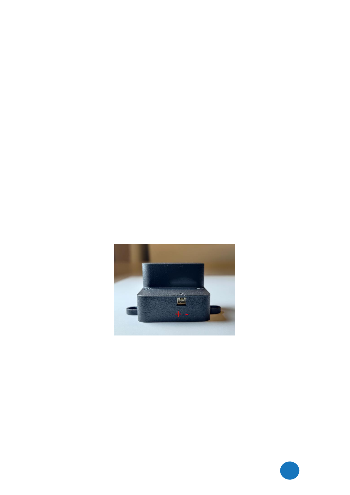
the db121pcb needs to be connected to a power source (from the drone) and has a JST-GH 1.25mm
2-pin power connector. It needs an input voltage between 4.5 V and 14 V. (15 V is the real maximum
input voltage. A higher voltage may damage the transponder.) The current profile is shown in
Chapter 3. Pin 1 needs to be connected to the input voltage and pin 2 to GND. Near the connector
there are markings to explain the pin-layout (
+
= pin 1 and
-
= pin 2). Alternatively, there is an AUX
power input (unpopulated 2.54mm pin header) that can also be used. This is indicated by the PWR
AUX marking on the PCB. Note that this AUX power input has a diode to protect it against reverse
currents. The main JST-GH connector has no diode for reverse currents to allow for lower input
voltages. (Voltages slightly lower as 5V are allowed.)
status led
The status led should be visible by the user. And the user can only take-off if the status LED is
flashing. If it is not visible, it will void the FAA DoC status of the db121pcb product!
1.5 Using the db121/db121pcb
Power on the drone; the db121/db121pcb will be powered too.
Wait for a GPS fix (slowly flashing status LED every 4 seconds). This is typically within 90
seconds if the db121/db121pcb is used outdoor.
You are ready to fly.
Battery/status LED
The status LED can have the following states:
-Ready for take-off: slowly flashing (every 4 s), location acquired.
- Non-compliant config: very slow flashing (every 20s), location acquired
- Acquiring location
Note:
For typical use in the USA no configuration is required. USA: use the db121/db121pcb S/N
number for registering your drone at the FAA.
For the EU, you need to enter your operator ID.
A non-compliant configuration can be caused by selecting a non-compliant transmission
protocol, selecting a lower transmit power (for WLAN modes) or selecting a different channel
for WLAN modes than the default channel 6.
Flying a drone could create risks for people, air traffic and other assets. Before
flying, the drone operator has to make sure to know the local rules regarding
drone flights and obtain the necessary authorization to fly the drone(s).
1.6 EMC test
To verify that the db121/db121pcb does not produce interference to the drone or receives
interference from the drone, it is advised to do a quick EMC test. (Only when attached for the first
time to a drone.)
Power on the drone and remote control. Keep the db121/db121pcbpowered off.
Verify that the drone, remote control and wireless link are functioning properly.
e
e
l
e
e
l
e
e
e
e
l
e
e
l
e
e
e
e
l
e
e
l
e
e

DroneBeacon db121/db121pcb manual - version 1.1 April 2023 - © BlueMark Innovations BV 2023
10/19
Power off the drone and remote control.
Power on the db121/db121pcb (using a different power source). Keep the drone and remote
control powered off.
Verify that the db121/db121pcb is functioning properly. For instance by using the Android in
Section 1.6 or by looking at the status LEDs (ready for take-off state).
Repeat the tests by powering on both the db121/db121pcb, the drone and remote control. If
both the db121/db121pcb and drone, remote control and wireless link are functioning
properly, there is no EMC interference between both systems.
In case there is interference, please move the db121/db121pcbto a different place on the
drone and repeat the tests. Alternatively lower the output power or change the transmission
protocol.
1.7 Android/iOS app
You can use the free
OpenDroneID OSM
Android app to view the DroneBeacon Remote ID signals:
https://play.google.com/store/apps/details?id=org.opendroneid.android_osm
Or the Drone Scanner Android app:
https://play.google.com/store/apps/details?id=cz.dronetag.dronescanner
Note: only few Android smartphones support reception of Bluetooth Long Range and/or WLAN NaN
signals. Also, in default Android configuration, WLAN Beacon signals are typically received only
once every few minutes. A list of supported smartphones is presented, in the link below.
https://github.com/opendroneid/receiver-android/blob/master/supported-smartphones.md
iOS
The Drone Scanner app is also available for iOS. Due to limitation of iOS only BT4 reception is
possible.
https://apps.apple.com/gb/app/drone-scanner/id1644548782
1.8 Open Drone ID
DroneBeacon uses the Open Drone ID framework to broadcast Remote ID signals. The framework
can be found on this page: https://www.opendroneid.org/

DroneBeacon db121/db121pcb manual - version 1.1 April 2023 - © BlueMark Innovations BV 2023
11/19
2 CONFIGURATION
The transponder can be configured via a web-interface. To active the configuration mode follow
these steps:
Move the on-off power switch to
on
(to power up the transponder).
Press the configuration button, the
red
configuration LED is turned on.
Connect to the
dronebeacon
WLAN network (no password needed)
Point your browser to http://192.168.50.1
New settings will only be applied if the Save button is pressed!
Configuration mode will be quit, by pressing the configuration button again.
The
red
configuration LED is now turned off. The transponder is now in
normal operation mode.
2.1 General
The main configuration can be found on the general tab.
Figure 2 - General configuration page
Fill in the drone type of your drone.
2.2 Operator
In the operator tab, you can configure the details of your license provided by the National Aviation
Authority. This is an optional setting for the USA. In the USA you need to use the serial number of
the db121/db121pcb instead for register your drone at the FAA. For the EU, this is a mandatory
setting.
First, select the region where the drone is flying
. Outside the EU, no UAS category or UAS
class is required.
configuration web-page

DroneBeacon db121/db121pcb manual - version 1.1 April 2023 - © BlueMark Innovations BV 2023
12/19
Within the EU, only valid license numbers can be entered. In that case the input box becomes green.
Figure 3 - Operator configuration page
2.3 Flight
In the flight tab, you can configure an
optional
text describing the purpose of your flight.

DroneBeacon db121/db121pcb manual - version 1.1 April 2023 - © BlueMark Innovations BV 2023
13/19
Figure 4 - Flight configuration page
2.4 Radio
In the radio tab you can configure the transmission mode and other radio-related settings. Most
users don’t change settings in this section. Note that in the USA only BLE dual-mode and WLAN
broadcast transmission mode are allowed.

DroneBeacon db121/db121pcb manual - version 1.1 April 2023 - © BlueMark Innovations BV 2023
14/19
Figure 5 - Radio configuration page
2.5 Firmware
In the firmware tab, you can upgrade the firmware of the transponder.
Firmware files can be found here: https://dronescout.co/downloads/
(Version history: https://download.bluemark.io/dronebeacon_transponder_history.txt)
Upload the file and press Flash image to upload new firmware. Upgrading firmware has been tested
with Chrome and Firefox. If upgrade fails, please try again or try another browser.

DroneBeacon db121/db121pcb manual - version 1.1 April 2023 - © BlueMark Innovations BV 2023
15/19
Figure 6 - Firmware upgrade page

DroneBeacon db121/db121pcb manual - version 1.1 April 2023 - © BlueMark Innovations BV 2023
16/19
3 CURRENT PROFILE
The current profile has been measured using a digital current meter with a ~ 7.2 kHz sampling rate.
Below the current profile (db121/db121pcb) has been shown for 5 seconds. Here, Bluetooth legacy
and Bluetooth Long Range have been enabled. Also, the module transmits with maximum transmit
power (+18 dBm). On the left the module is powered off and then connected to power (+5 V).
The startup current profile is shown in the first 1.7 seconds.
The
average
current is 84 mA (~ 420 mW).
The
median
current -if there is no transmission- is 66 mA (~ 330 mW).
The
peak
current is 400 mA2(~ 2 W).
If the transmit power is reduced in the firmware, the peak current will also be smaller.
Figure 7 - Current profile of the db121/db121pcb transponder with BLE legacy and BLE Long Range enabled (input voltage
+5V)
2The maximum
instantaneous
current may be higher, as the maximum value is limited by the sample rate of
the current meter.

DroneBeacon db121/db121pcb manual - version 1.1 April 2023 - © BlueMark Innovations BV 2023
17/19
4 TROUBLESHOOTING
Access to the configuration web-pages fails.
Failing to access the configuration web-pages can have multiple causes. Make sure the
configuration LED is solid red. Also, make sure that you connect to the
dronebeacon
network. If you
get a message that the network does not provide internet, make sure you decline the message to
disconnect and connect to your default WLAN network again. The browser
Safari
can also give
issues to connect to the configuration web-pages. Use a different browser in this case. Also, a VPN,
browser add-ons or another active internet connection can give issues. Disconnect the VPN and
other internet connections. The easiest solution is use a different device to connect to the
configuration pages.
The configuration LED and some battery LEDs glow softly when the db121 is powered on.
If the configuration button is stuck, the db121 will not boot normally, but instead will enter a special
boot mode. If this is the case the configuration LED and a few battery LEDs will glow softly. To solve
this, make sure that that the configuration button is not pressed or is stuck by the enclosure.
The reported height is wrong.
The db121 uses the GNSS (GPS) signal to determine the height of the db121. It needs a good GPS
reception/fix for this purpose. Make sure you install the db121 on top of your drone. Also, db121/
GNSS receiver has issues to track slow vertical speeds. Make sure you always go up or down with at
least 1 m/s vertical speed for your drone.
The db121 interferes with the drone communication link.
Move the db121 to a location further away from the drone communication antenna. Even 10 cm
extra distance can make a huge difference. See also section 1.6 EMC test. In addition, change the
transmission protocol if the interference persists. Typically, Bluetooth transmission protocols cause
less interference to other radio systems. Also a lower the transmit power will reduce interference.
The db121 gets no GPS lock/location data.
In normal outdoor situations, the db121 gets a GPS fix typically within 90 seconds. In indoor
locations or blocked GPS reception, a GPS fix may take considerably longer or not all. Please contact
us, in case the GPS fix takes always a very long time or there is no GPS fix at all.

DroneBeacon db121/db121pcb manual - version 1.1 April 2023 - © BlueMark Innovations BV 2023
18/19
5 WARRANTY
The product has a two-year warranty period, starting at the date of receiving the product. Outside
warranty are issues like crash damage, improper use, (extreme) weather conditions that damages
the product. Also, the battery is excluded from warranty. The product is eligible for future firmware
updates as described in the section 2.4 firmware.
Warranty Service
Please email or call us first with a description of the problem. Typically, the customer is responsible
for transportation costs to our office. For post-warranty cases contact us too; we will try to do our
best to find a solution.

DroneBeacon db121/db121pcb manual - version 1.1 April 2023 - © BlueMark Innovations BV 2023
19/19
6 MORE INFORMATION
If you need more information, please contact us at info@bluemark.io or by phone: +31 53 711 2104.
All contact information can be found at the
DroneScout
contact page:
https://dronescout.co/contact/
Table of contents
Other Blue Mark Marine Radio manuals
Popular Marine Radio manuals by other brands

Cobra Marine
Cobra Marine MR HH100 user manual

ACR Electronics
ACR Electronics Nauticast2 2609 installation manual

Humminbird
Humminbird Marine Radio user manual

Comar Systems
Comar Systems CSB200 Installation and instruction manual

GME
GME G-COM GX800W instruction manual

NorthStar
NorthStar EXPLORER 705 - quick start guide