Blue Point Engineering Puppeteer Plus User manual

Puppeteer Plus Board Controller
Instruction I
Blue Point
Pointing the Way to Solutions!
Engineering www.BPEsolutions.com
9-12 VDC
(BPE No. PCA-0001)
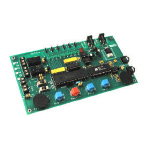
The Puppeteer plus board provides up to 4 minutes of recording and playback time for one servo channel
and one digital (relay) output channel. The board supports sequential recording functions, daisy chaining
and loop playback with variable inter-loop timing and automatic start-up positioning.
Board Connections
Power Supply Header
The Puppeteer plus board requires +5V DC supply at currents up to 0.5 amps depending on servo used.
Servo Header
Three pin header to connect to standard servos- observe polarity of servo connection wire (R,B,W)
The Puppeteer plus board generates pcm signals between 0.5 and 2.5msec long repeated every 20msecs.
Note: Most servos are generally only rated for 1-2msec pulses so care should be taken at the extreme
ends of the travel to ensure the servo motor is not damaged by the extreme travel.
3-Way Terminal Block
Switched relay outputs. The relay is rated at 24V DC @ 1 Amp (NO, Comm, NC terminal connections)
Controls
Go Switch Button
Press and release to record the servo and digital(relay) actions.
Press and release to initiate playback modes.
Go Pins
Used for daisy-chaining multiple Puppeteer plus board - connect subsidiary module Go pins to the sync
output pins.
R/P Pins
Selects either Record mode (jumper IN place) or Playback mode (jumper OUT).
S/R Pins
Selects either loop playback Repeat (Jumper OUT) or Single playback (Jumper IN)
Reset Pins
Resets the Puppeteer plus board. (Briefly short the Reset jumper pin pair to reset the controller)
Servo Connection
Servo Position Adjustment
GO Button
Power Connection 5 Vdc
Playback LED
Record LED
Sync.
Relay LED
EEPROM
Relay Connection Digital Button
Playback
LED
Reset
S/R
GO
R/P
Puppet - II+
Battery Cells
- Black
- Red
- Yellow / White
- N/C
- Com
- N/O

9-12 VDC
Sync Pins
Used for daisy-chaining multiple Puppeteer plus board - connect subsidiary module Go pins to the sync
output. Output normally high (+5V), drops to 0V for 50 msecs at the beginning of each playback or
recording session.
Digital Switch Button
Press to activate the relay either in manual standby or record modes.
Potentiometer
Adjusts the servo position during manual standby or record modes.
Adjusts the inter-loop playback delay period when loop play selected (S/R Jumper OUT)
The minimum delay period is approximately 5 secs (left) the max is approximately 50 seconds (right).
Operation
First recording
• Power ON the controller with NO jumpers in place to test. The servo should respond to movement of
the position control wheel and the relay operate when the Digital switch is pressed ON/OFF.
• Turn the power to the Puppeteer plus board OFF.
• Insert the R/P jumper and turn ON the power to the board. The Red LED will start to flash. The
Puppeteer plus board is now ready to begin recording of the servo channel and digital channel.
(Since this is the first recording since power was applied to the module, the recording will begin at the
start of memory. For adding to a pre recorded program, see the "follow-on recording" below.)
• Press and release the GO button to start record, the Red LED will stay ON. Adjust the servo position
using the movement control wheel and/or operate the digital (Relay) action by pressing the DIGITAL
button as needed ON and OFF. Digital On/Off action and servo motion positions are recorded together.
• Press and release the GO button. (the controller is now in pause mode) You have two options at
this point. (1) Remove the R/P jumper to exit recording mode, or (2) If you want to keep recording
leave the R/P jumper IN and press the GO button to continue with more recording. In pause mode the
Green LED will turn ON this is a guide to ensure smooth splicing of subsequent recording sessions. If
you move the position control the Green LED will turn OFF and will only re-light when the servo is in
the exact same position it was at the end of the previous session.
• Remove the R/P jumper when the module is paused (Red LED flashing) to exit any recording mode.
Playback
Single Playback
• Insert the S/R jumper only (IN). Press and release the GO button to playback the recorded session.
At the end of the session, the servo will move to a position dictated by the last position of the movement
control wheel and wait for the next press of the GO button (Green LED ON indicates playback mode is
playing recorded routine. Green LED will turn OFF at the end of playback routine).
Looping Playback
• Remove the S/R jumper (OUT) for loop playback, the position control will now be read at the end of
the playback session and the interloop delay time calculated from this position value. The minimum wait
period is approximately 5 secs (left) the maximum time approximately 50 seconds (right). At the end
of the session, the servo will move smoothly to its start-up position to avoid sudden actions. (Green LED
will blink indicating wait delay is active in count down before next playback starts automatically).
Follow-on Recording
Module still powered up after a previous session:
The Puppeteer plus board will remember the last saved position details- proceed as though starting a
new recording except that with the Red LED is flashing- adjust the servo position until the Green LED
turns ON to ensure a smooth continuation of actions.
Module newly powered up:
Playback the stored moves – this will load into the Puppeteer plus board the location of the last move.
Proceed as per the standard follow-on recording above.
Existing session prematurely terminated:
Playback the stored moves. At the required termination point, insert the R/P jumper (IN). This will
stop playback and load into the Puppeteer plus board the position of the last move. Proceed as per a
standard follow-on recording, the new recording will begin at the point playback was stopped, R/P (IN)
Sync.
Reset
S/R
GO
R/P
Puppeteer Plus Board
Battery Cells
- Black
- Red
- Yellow / White
- N/C
- Com
- N/O

9-12 VDC
Sync.
Reset
S/R
GO
R/P
Puppeteer Plus Board
Battery Cells
- Black
- Red
- Yellow / White
R/C Servo
Connection
B
A
C
Standard +5 Volt dc
R/C Servo
Servo
Positions
Power
Connection
5Vdc
Wall Plug Power Supply
5 Vdc @ 0.5 Amp
Wall Power
Adapter
GO Button
Playback LED
Record LED
Relay LED
GO
Sync.
Reset
S/R
R/P Relay
Servo Position
Control / Adjustment
Digital Button
Relay
Connections
Configuration
Jumpers
Caution
Check Correct
Polarity (+/-).
( Relay Output )
BLACK Wire
RED Wire
Caution
Check Correct
Servo Connection
Optional 5vdc 10 mA
Digital output connector
Jumper
IN
- N/C
- Com
- N/O
24V DC @ 1 Amp
Jumper
OUT

Puppeteer Plus Board
+ Vdc - Vdc
Wall Plug Power Supply
5 Vdc @ 0.5 Amp
Wall Power
Adapter
RED Wire Power
Connection
5Vdc
Relay
Connections
BLACK Wire
- Com
- N/O
24V DC @ 1 Amp
Relay
Relay
Wire
Terminal
Air
Compressor
Pneumatic Cylinder
12 Vdc
Power Supply
Pneumatic
Tank
Air
Filter
Pressure
Regulator
Air Hose
Pneumatic
Valve
Air
Hose
Air Hose
Air Hose + 12 Vdc
+ 12 Vdc
- 12 Vdc
Wire
Wire
Wire
Pressure
Gauge
Quick Disconnect
Hose Connectors
Accumulator
Tank
Puppet Plus - Controller Board
Optional Pneumatic Output Mode
Electrical Pneumatic Valve
12 VDC 3-15 VDC
240 VAC
Green
(Gnd)
White
Black
Red
Black
Pressure
Gauge
12 Vdc
Copyright © 2002 Blue Point Engineering, All Rights Reserved

Puppeteer Plus Board
- Com
- N/O
Puppet Plus Controller Board
Optional Digital to AC Output Mode
+
-
12 VDC 3-15 VDC
240 VAC
+
Green
(Gnd)
Back
White
Solid-State Relay
Module
Plug In
AC Voltage
Wall Plug
White
Black
Red
Black
Caution:
* In no event shall Blue Point Engineering be liable for any claim for
incidental, consequential damages, or any injuries sustained due to the
use of or improper use of this circuit. This circuit should NOT be used
for any applications that could cause injury, dangerous / hazardous
situations or consequential damages. Use this circuit at your own risk.
* Use caution when working with AC Voltage.
Touching or incorrectly wiring this circuit
could cause serious personal injury or damage
to equipment.
250 WATTS
- Lights
- Sound System
- Fog Machine
- Effects Equipment,
- Etc.
Relay
Connections
24 Volts DC
@ 1 Amp
Relay
Wire
Connection
Terminal
Power Transformer
( 6-12 VDC)
*
*
Copyright © 2002 Blue Point Engineering, All Rights Reserved

- Com
- N/O
12 VDC 3-15 VDC
240 VAC
Green
(Gnd)
White
Black
Red
Black
MOTOR
POWER
+V
-Gnd
12 Volt DC
Permanent
Magnet Motor
Motor
Rotation
Puppeteer Plus BoardPuppet Plus Controller Board
Optional Small DC Motor Control Mode
12 Volt DC
Power Supply
Relay
Connections
24 Volts DC @ 1 Amp
Relay
Wire
Connection
Terminal
MOTOR
POWER
+V
-Gnd
12 Volt DC
Permanent
Magnet Motor
Motor
Rotation
12 Volt DC
Power Supply
A B
A B
OR
Red Wire
Black Wire
Red Wire
Black Wire
Copyright © 2002
Blue Point Engineering
All Rights Reserved

- Com
- N/O
12 VDC 3-15 VDC
240 VAC
Green
(Gnd)
White
Black
Red
Black
Phone (303) 651-3794
www.BPEsolutions.com
Blue Point Engineering
Custom Equipment, Unique Electronic Products
Relay
Connections
24 Volts DC @ 1 Amp
Relay
Wire
Connection
Terminal
Puppeteer Plus BoardPuppet Plus Controller Board
Optional LED Effect Control Mode
9 Volt dc
Power Supply
Resistors
Blue
LED's
2.3 Vdc
50 mA
150 Ohm 1/8 Watt
Red Wire
Black Wire
Copyright © 2002 Blue Point Engineering, All Rights Reserved
This manual suits for next models
1
Table of contents
Other Blue Point Engineering Controllers manuals
