Blue Point Engineering Wizard - 11 User manual

Wizard - 11 Board Controller
Instruction I
Blue Point
Pointing the Way to Solutions!
Engineering Inc.
Page 1
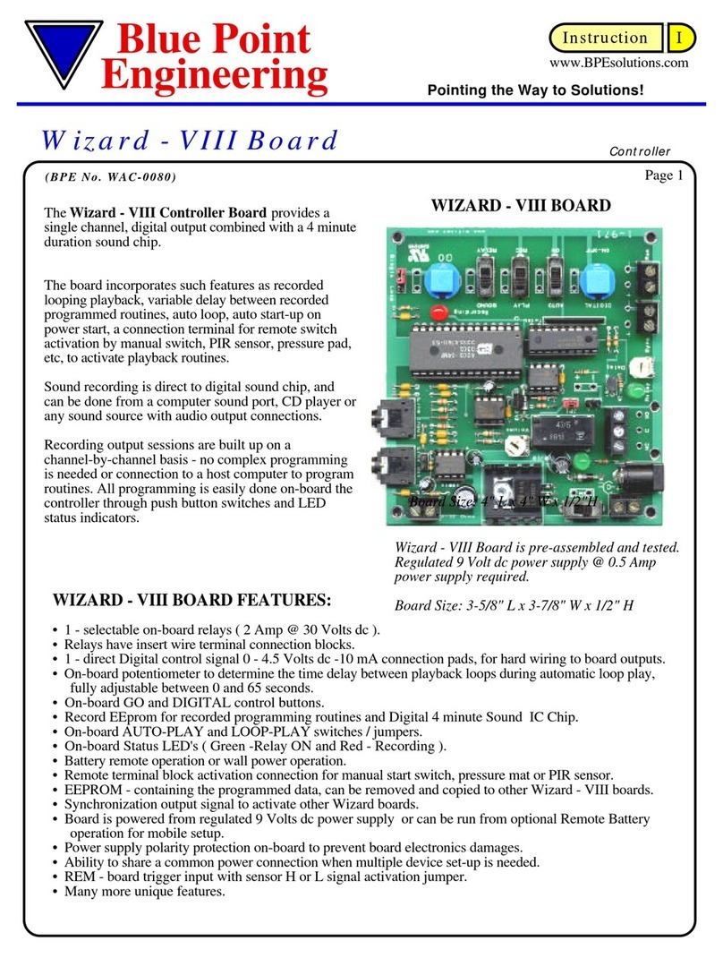
Wizard - 11 Board is pre-assembled and tested.
Regulated 9 Volt dc power supply @ 2 Amp and
Regulated 6 Volt dc power supply @ 5 Amp
power supply required
WIZARD - 11 BOARD
www.BPEsolutions.com
Board Size: 7-3/8" L x 4-1/8" W x 1/2"H
The Wizard 11 Board will record and playback up to
6 minutes of motion for up to 6 servos and On and
Off relay action for 2 digital outputs. It also
incorporates a 4-minute audio recording and playback
IC sound chip with the option to control one servo
channel from recorded moves, from an input audio
signal or directly from the on-board sound IC chip.
The board includes features such as looping action with
variable delay between loops, auto start-up on
power up and a connection terminal for a PIR, remote
switch or sensor to initiate playback start.
Recording sessions are built up on a simple channel
-by- channel method using on-board switches and
potentiometer control. No computer or complex
programming is required to operate board.
During recording, all previously recorded channels are
re-played to aid synchronization.
• 2 Digital channels - either 0 / 4.5 Volts @ 10mA outputs or change over relay rated 30V @ 2 Amp.
• 6 Servo channels – one channel (ch2) may be automatically controlled from an audio signal either from
the line input or from the on-board sound chip.
• 4 minute (240 sec) high quality sound chip - digital recording from line input.
( Computer sound card, CD player, wav files, etc.).
• Digital ON-OFF, NEXT, PLAY and RECORD on-board buttons.
• Servo action reversing option on the audio channel servo - 2
• Maximum and minimum servo travel set points for the audio servo channel - 2
• 2 - selectable on-board relays ( 2 Amp @ 30 Volts dc ).
• Relays have insert wire terminal connection blocks.
• 2 - direct Digital control signal 0 / 4.5 Volts dc -10 mA connection pads, for hard wiring to board outputs.
• On-board potentiometer to determine the time delay between playback loops during automatic loop play,
fully adjustable between 0 and 65 seconds.
• Record enable / disable jumper to protect recorded programming routine.
• On-board AUTO-PLAY and LOOP-PLAY switches.
• Maximum and Minimum set points to the audio servo channel (ch-2) and optional reversing servo action.
• Remote terminal block activation connection for manual start switch, pressure mat or PIR sensor.
• Programming and operation Green and Red status LED's.
• EEPROM - containing the programmed data, can easily be removed and copied to other Wizard - 11 boards.
• Synchronization output signal to activate other Wizard boards linked together.
• Board is powered from regulated 9 Volt dc power supply and 6 Volt dc power supply.
• REMote - board trigger input from remote sensor with H or L signal activation jumper.
• Many more unique features.
Position Potentiometer - Servo motion, Time delays
Adjusts the position of the currently selected servo travel ( Channel -1 through Channel - 6 )
Sets the audio channel end stops.
Sets the time delay between playback in loop-play, adjustable to between 0 to 65 seconds.
Board Functions: - CONTROL
WIZARD - 11 BOARD FEATURES:

Page 2
Digital - Key - On / Off -button
Pressing the Digital key will activate the current channel selected (ch -7 and 8) output relay as ON or OFF.
This is a momentary switch. Press and hold the Digital key, when you want the relay to be ON, release OFF.
Relay - N.C, C, N.O connections.
N.C = Normally Closed position of the relay contacts ( Circuit is ON- will open circuit (OFF) when activated )
C = Common connection to relay contacts.
N.O = Normally Open position of the relay contacts ( Circuit is OFF- will close circuit (ON) when activated )
Relay / Pin Output Jumpers. When this jumper is in place, the board will control the on-board relays. The
relays are rated at 30 V @ 2 Amp. When the jumper is removed, the relay is de-activated and the output pins
may be used as voltage drivers ( 0 Vdc or 4.9 Vdc @ 100mA when on). The pins are marked with Plus (+)
and Minus (-) for correct polarity connection. Use caution when connecting to the pins to observe correct
polarity (+ / - )
Play - key
Replays a set of recorded relay actions.
During play back the channel LED’s will form a bar-graph indicating the amount of time used.
When the recorded routine has finished playing the bar-graph-LED’s will go out.
A switch, sensor may be connected to the REM connection and this will function in the same way as the
Play-key.
Next - channel key (servo ch 1-6, Relay ch 7-8, sound IC chip)
Changes the current active channel to the next channel.
Each key-press selects the next channel - servos 1 and 2, digital 3 and 4 and the sound chip.
Record - key (Servos, Relays and Sound IC)
The record - key has no effect unless enabled by the record-enable E/D Jumper. (see drawings for details)
Press and release the record key to start recording a routine. Press and release the Record-key to stop
recording. If the Record-key is held down when power is applied to the board, all memory will be erased.
(Takes approximately 20 seconds, LED will form a bar-graph indicating EEprom erasing is occurring.).
During the recording of a channel the LED’s will form a bar-graph indicating the amount of time being used.
When the action has finished playing the bar-graph-LED’s will turn off.
RECORD NOTE:
The recording on channel -1 will set the maximum available recording time for all other channels.
Always record channel -1 first, then the other channels ( 2-4 ). Recording periods for channels 2-4 cannot
be longer than for channel -1.
Record D / E Jumper - EEprom Protect.
The Record / Enable jumper protects the programmed routine in the EEprom. If the jumper is set at the "E"
enable position then recording will be permitted. Move the jumper to "D" disable recording to prevent
recording to the EEprom. The Record button E/D jumper will enable or disable button from operating.
SYNC Terminal - Output
Synchronizing connection for multiple board to be linked together. On-board terminal connection delivers a
pulse signal (50 msec) at the start of playback and record event which may be used to trigger other Wizard
boards connected in a chain or master module - slave module setup. SYNC output to REM input of other
boards.
REMote Terminal
Used to trigger Wizard board by remote switch, sensor. Can also be wired together for no-stop playback.
REM Jumper - H and L positions. ( Sensor N.O. or N.C. relay input option)
To begin playback when the input line drops from + to ground, set the REM jumper to the L position. To
begin playback when the action input goes from ground to + (sync pulse) set to the H position
LOOP -slide switch.
To make the Wizard - 11 board play the recorded moves repeatedly, move the switch to the "Y" position. The
recorded moves will start to play when the PLAY-key is first pressed. There will be a pause at the end of
playing (determine by the position of the Loop Delay control) after which the recorded action will start again.
Note: To record new program routines, the LOOP switch must be set to the "N" position.

LOOP -delay.
Pause between playback loop option.
When the Wizard - 11 board is set to the LOOP "Y"position, the length of the pause between repeated
playbacks may be set by the on-board Loop Delay control potentiometer.
Turn theLoop Delay control counter clockwise (CCW) for the minimum delay (approximately 2 seconds and
clockwise for the maximum delay (approximately 65 seconds).
AUTO - slide switch.
To make the Wizard - 11 board play the recorded moves repeatedly on power - ON or reset, move the switch to
the "Y" position. The recorded actions will start to play on any power-up.
Note: to record new program moves, the AUTO switch must be set to the "N" position.
Servo 2 - Options (Programmed movement or Auto - Sound to Motion)
Set the jumper (Servo - 2) to theEEprom position to record and playback moves in a similar manner to Servo
Channel 1. (Programmed motion)
Set the jumper to Audio to control the movement of Servo - 2 from an audio signal (line in or from sound chip)
When set to audio, the audio signal generated by either the on-board sound chip or a suitable line input signal is
sampled and used to control the servo movement. This feature is particular useful for "Mouth" servo operation
as it requires no special user programming synchronization needed with a sound source. Use the Audio Source
jumper to select from the on-board sound Chip or the Line input jack.
Using Servo - 2 with an Audio Control Signal (sound IC or line input source)
Setting Servo - 2 travel end points
Select the required audio source (On-board chip or line input jumper)
Set the servo travel end points for servo - 2. Press and hold the NEXT key and apply power to the board.
LED -S will start to flash and servo - 2 can be controlled by the Position potentiometer. Move the servo to one
end point of the required servo travel range. Press the Digital button.
LED -R will now flash - adjust the servo position to the other end of the servo limit and press the Digital button.
LED -R will now turn off and the control board will return to a normal operation mode ( LED-1 will turn on).
The two servo limit travel points have been stored in memory and will limit the travel of Servo -2 when
responding to an audio signal.
The degree of Servo - 2 movement is governed by the combination of the sound source volume and the Gain
presets. Rotate the Gain potentiometer on-board, clockwise for maximum signal gain and maximum servo
movements.
Audio Channel - Reverse / Normal Jumper
Setting the jumper to the Reverse position will cause the motion of Servo - 2 to be reversed (operate in the
opposite direction currently moving)
Audio Setting
INPUTS - ( 150 mVolts P-P Level )
Line Input - audio source going into the Wizard - 11 board (CD player, computer, stereo, etc.),usually to be
recorded to the Sound IC chip, or to drive Servo - 2 directly.
OUTPUTS - ( 2.5 Volts P-P Level )
Line Output - audio from the on-board sound chip going out to a remote external powered speaker or amp
system. The audio from the sound IC chip is slightly amplified to operate an 8 Ohm speaker directly only for
playback audio review. In normal use the audio output should be connected to a remote external powered
speaker or amp for best sound results and volume.
Page 3
Clearing Memory to start a new program.
The Enable jumper must be set at the (E) position and the Record-key jumper also set to the (E) position.
The LOOP switch and the AUTO switch must be in the "N" position.
The RECORD - key is held down during Power Up, and released after power is applied.
The LED's "1-4" will form a count down bar-graph indicating that current programmed
EEPROM memory is being cleared. (This will take approximately about 20 seconds).
After the initial 20 seconds all green LED’s will turn OFF and the current selected
channel LED will turn ON, indicating the board is now ready for new programming.
Power Connection Solder Pads:
When powering the board from a regulated supply, the supply wires can also be soldered to the holes directly
for a more permanent connection. Observe polarity + and - to prevent damaging the board.

Page 4
Examples
1. Recording - Servo Motion and Relay Action On and Off - New program start
Make sure that the EEprom E/D jumper is set at the (E) position and that the Record key -E/D jumper is also
set to the (E) position. The LOOP and the AUTO switch must be in the "N" position.
Power down the Wizard -11 controller and then hold down the record key and apply power back to the board,
all memory will be erased (LED's will count down, approximately 20 sec.)
Select Servo Channel -1 by pressing NEXT-channel-key until the green number 1 - LED is ON.
Press and release the RECORD-key. (The red LED will turn ON, record mode is now active)
Adjust the Position Potentiometer, moving Servo - 1 as needed. ( approx. 2 minutes)
Press and release the RECORD-key to end recording session and set total record time (5 Min Max).
Select Relay - 1 Channel by pressing NEXT-channel-key until the green number 3 - LED is ON.
Press and release the RECORD-key to start recording session for relay.
Press and hold the Digital - key for approximately 1 minute, then release the Digital key switch.
Relay - 1 will turn On and Off, as you press and release Digital key.
( Note: Servo Channel -1 will playback previously recorded action to help in synchronization of the new
channels being recorded )
The recording will end automatically after approximately 2 minutes ( established by channel - 1 recording
time used )
Playback of Recorded Program Servo Channel -1 and Relay -1
Press and release the PLAY-key to review the recorded sequences.
Relay -1 and Servo Channel -1 will playback recorded actions, then wait for PLAY-key to be pressed again.
Programming Servo - 2 as a Recorded Routine.
Make sure that the EEprom / Audio jumper is set at the (EEprom) position and that the EEPROM E/D jumper
and the Record key jumper is also set to the (E) position. The LOOP and the AUTO switch must be in the "N"
position.
Select Channel -2 by pressing NEXT-channel-key until the green number 2 - LED is ON.
Press and release the RECORD-key. (The red LED will turn ON, record mode is now active)
Adjust the Position Potentiometer, moving Servo - 2 as needed.
( Note: Relay -1 and Channel -1 will playback previously recorded action to help in synchronization of the new
channels being recorded )
The recording will end automatically after approximately 2 minutes ( established by channel - 1 recording
time first set).
NOTE: The recording on channel - 1 will always set the maximumavailable recording time for all other
channels. Always record channel - 1 first, then the other channels. Recording periods for channels 2 cannot
be longer than for channel - 1. ( Maximum recording time for servos and relays is 5 minutes).
Examples
2. Editing a Servo Channel (channel -2 example)
You can re-program Servo channels 2, by pressing the NEXT-channel-key until Channel -2 green LED is ON.
Press and release the RECORD-key. (The red LED will turn ON, record mode is now active)
Adjust the Position Potentiometer, moving Servo - 2 as needed.
The recording will end automatically based on Channel -1 recorded time.
Remember that Channel -1 sets the maximum time for all the channels. if you re-program Channel -1 with less
time then previously recorded, all the other channels will also be adjusted to meet the length of Channel -1
record time if longer times were originally recorded for them.
If re-programming Channel -1, then you will need to always press and release the RECORD-key, a second
time, after re-programming Channel - 1 to end the programming sequence, and set record time line.
3. Editing Relay Channel - 1
You can re-program Relay Channel - 1 by selecting the NEXT-channel-key until Channel -3 green LED is
ON. Press and release theRECORD-key. (The red LED will turn ON, record mode is now active)
Press and release the Digital - key as needed. The recording will end automatically after approximately 2
minutes ( established by Channel - 1 recording time first set)

Page 5
Make sure that the EEprom E/D jumper is set at the (E) position and that the RECORD-key -E/D jumper is
also set to the (E) position. The LOOP and the AUTO switch must be in the "N" position.
Make sure that the Audio Source Jumper is set to the Chip position.
Connect a audio cable from a sound source (CD player, Computer sound port, Stereo, etc.) to the Line Input
Jack on-board the Wizard - 11 board. ( need 150 mV P-P input from sound source to operate Wizard - 11
board sound system)
Select Sound Chip by pressing NEXT-channel-key until the green S- LED is ON.
Press and release the RECORD-key at the same time that you start sound source. (CD player, Computer
sound port, Stereo, etc.), The red LED will turn ON, record mode is now active. The sound source is now
being digitized into the sound IC chip. The sound recording will end automatically after 4 minutes, or you can
Press and release the RECORD-key to stop recording sound.
Playback of Recorded Program Servo Channel - 1, Relay - 1 and Sound.
Connect an audio cable from the Line Output Jack on-board the Wizard - 11 to a remote amplified speaker
unit. Make sure that the amplified speaker is turned on, and volume set below the mid level point to start.
Press and release the PLAY-key to review the recorded servo, relay and sound..
Servo Channel -1, Relay -1 and Sound will playback recorded actions and end.
Press the PLAY-key to be start again.
LOOP -slide switch.
To make the Wizard - 11 board play the recorded moves repeatedly, move the switch to the "Y" position. The
recorded moves will start to play when the PLAY-key is first pressed. There will be a pause at the end of
playing (determine by the Loop Delay control from Position potentiometer) after which the recorded action
will start again. Note: To record new program routines, the LOOP switch must be set to the "N" position.
LOOP -delay (Position potentiometer)
Pause between playback loop option.
When the Wizard - 11 board is set to the LOOP "Y"position, the length of the pause between repeated
playbacks may be set by the on-board Loop Delay control (Position potentiometer).
Turn theLoop Delay control counter clockwise (CCW) for the minimum delay (approximately 2 seconds
and clockwise (CW) for the maximum delay (approximately 65 seconds +/-).
AUTO - slide switch.
To make the Wizard - V board play the recorded moves repeatedly on power-up or reset, move the slide switch
to the"Y" position. The recorded actions will start to play on any power-up.
Note: to record new program moves, the AUTO switch must be set to the "N" position.
Examples
5. Operating Servo Channel - 2 in Auto Sound to Motion Mode
Using on-board Recorded Sound IC Chip to Operate Servo - 2
Make sure that the sound IC Chip has been recorded with needed audio.
Check to see that the Servo - 2 EEprom / Audio jumper is set at the (Audio) position.
Check to see that the Audio Source jumper is set at the (Chip) position.
Set the servo travel end points for servo - 2 ( see above - Setting Servo - 2 travel end points )
Press and release the PLAY-key to playback the recorded servo, relay and sound..
Servo Channel -1, Relay -1 and Sound will playback recorded actions and Servo - 2 will operate in response
to the Audio from the Sound IC Chip. (You may need to adjust Gain control to get servo - 2 moving).
Press the PLAY-key to be start again, or set the Loop and Auto slide switches to optional modes.
Using External Remote Audio Source to Operate Servo - 2
Check to see that the Servo - 2 EEprom / Audio jumper is set at the (Audio) position.
Check to see that the Audio Source jumper is set at the (Line) position.
Connect a audio cable from the remote sound source (CD player, Computer sound port, Stereo, etc.) to the
Line Input Jack on-board the Wizard - 11 ( need 150 mV P-P input from sound source to operate)
Set the servo travel end points for Servo - 2 ( see above - Setting Servo - 2 travel end points )
Start the external sound source, and adjust the Gain control on the Wizard - 11 board to get Servo - 2 moving.
Press the PLAY-key to start playback, of Servo - 1 and Relay - 1 or set the Loop and Auto slide switches to
optional modes.
Examples
4. Recording - To Sound IC Chip

IMPORTANT NOTE: Clearing Memory
When clearing memory, only the servo and digital output recorded actions are erased.
The sound IC chip can only be cleared by re-recording over the current sound.
You must re-set Servo - 2 travel end point after clearing memory each time, if using AutoTalk
Feature. Servo - 2 will not respond under sound activation if you have not re-set the travel points,
after doing a clear memory.
Clearing Memory
The Enable jumper must be set at the (E) position and the Record-key jumper also set to the (E) position.
The LOOP switch and the AUTO switch must be in the "N" position.
Remove Power to the Wizard - 11 Board.
Hold down the RECORD - key and re-apply power back to the board, released after power is applied.
LED's "1-4" will form a count down bar-graph indicating that current programmed
EEPROM memory is being cleared. (This will take approximately about 20 seconds).
After the initial 20 seconds all green LED’s will turn OFF and the current selected
channel LED will turn ON, indicating the board is now ready for new programming.
The servo and digital
Reset of Servo - 2 Travel End Points.
Setting Servo - 2 travel end points
Select the required audio source (On-board chip or line input jumper)
Set the servo travel end points for servo - 2. Press and hold the NEXT key and apply power to the board.
LED -1 will start to flash and servo - 2 can be controlled by the Position potentiometer. Move the servo to one
end point of the required servo travel range. Press the Digital button.
LED -2 will now flash - adjust the servo position to the other end of the servo limit and press the Digital
button.
LED -2 will now turn off and the control board will return to a normal operation mode ( LED-1 will turn on).
The two servo limit travel points have been stored in memory and will limit the travel of Servo -2 when
responding to an audio signal.
The degree of Servo - 2 movement is governed by the combination of the sound source volume and the Gain
presets. Rotate the Gain potentiometer on-board, clockwise for maximum signal gain and maximum servo
movements.
I am trying to get Servo - 2 to operate from the sound IC Chip, or from a Line Input remote audio
source, but the servo is not moving to any sound.
Check to see that the Servo - 2 EEprom / Audio jumper is set at the (Audio) position.
Check to see that the Audio Source jumper is set at Chip for playback from the on-board IC Chip or
is set to Line for a remote audio input signal.
Check to see that you have a good remote sound source for Line input.
Check the Audio cables from the sound source to the Wizard - 11 Line Input Jack.
Check to see that the Sound IC has the recorded audio needed.
The degree of Servo - 2 movement is governed by the combination of the sound source volume and
the Gain presets. Rotate the Gain potentiometer on-board, clockwise for maximum signal gain and
maximum servo movements.
Reset new travel endpoints for Servo - 2 (See Reset of Servo - 2 Travel End Points)
Problem Help Guide - Audio Servo
Q
A•
•
•
•
•
•
•
Phone (303) 651-3794
www.BPEsolutions.com
Blue Point Engineering
Custom Equipment, Unique Electronic Products
Page 6
•See Wizard - 11 Controller Troubleshooting Hint pages for additional help.

Wizard Board Three ......
VDC 3-15 VDC
240
VAC
Green
(Gnd)
White
Black
Red
Black
LOOP
AUTO
LOOP
AUTO
Copyright © 2005 Blue Point Engineering , All Rights Reserved Version 1.0
PC Board
Page 7
Power Supply
The Wizard - 11 control board works with duo power supplies;
9 Vdc @ 2 Amp.
6 Vdc @ 5 Amp. or 5 Vdc @ 6 Amp
A small 2.1 mm socket with center positive is built-on board for quick power connections.
Connector
Regulated
+ 9 Volt DC
Wizard -11 Controller Board
Power Supply Overview
9 Vdc @ 2 Amp
+ Vdc
center
- Vdc
2.1 mm
Connector
Regulated
Power
- Vdc
outside
+ Vdc
center Red
Black
Wall Plug Power Supply
REGULATED 9 Vdc @ 2 Amp
Recommended
outside
2.1 mm
Connector
N
Y
N
Y
Wall Plug Power Supply
REGULATED 6 Vdc @ 5 Amp
2.1 mm
Connector
Connector
Regulated
+ 6 Volt DC
6 Vdc @ 5 Amp

Phone (303) 651-3794
www.BPEsolutions.com
Blue Point Engineering
Custom Equipment, Unique Electronic Products
Copyright © 2005 Blue Point Engineering , All Rights Reserved Version 1.0
Page 8
AudioTalk
Servo Motion Function
Wizard - 11 Controller Board
Jumper Overview
Servo - 2
AutoTalk
EEprom
Programmable
Control Audio Talk
Feature
Relay
Relay
De- Activated
Relay
Activated
Audio Source
Chip
Line
E D
EEPROM
Wizard Board Three ......
VDC 3-15 VDC
240
VAC
Green
(Gnd)
White
Black
Red
Black
LOOP
AUTO
LOOP
AUTO
REM Port
H L
Loop
N
Y
N
Y
Auto
Reverse Normal
Position
Potentiometer
Wheel
Wall Plug Power Supply
REGULATED 6 Vdc @ 5 Amp
2.1 mm
Connector
Protection

Page 9
Copyright © 2005 Blue Point Engineering , All Rights Reserved Version 1.0
Wizard - 11 Controller Board
Remote Activation / Auto-Playback
Playback Option Modes
REMOTE SWITCH
• Floor Mat Switch.
• PIR Sensor.
• Manual Operated Switch.
• Relay Contact Switch, etc.
To replay the recorded action repeatedly, the LOOP selection switch
must be in the "Y" position. The length of the pause between repeated
playback is set by the Delay control, CCW (5 sec.) or CW (65 sec.).
The PLAY key or REMOTE switch must be pressed once to start the
playback action or if The AUTO selection switch is set to the "Y"
position, then the recorded playback action will begin automatically
each time on power-up.
Note: For a "0" pause delay between playback, set the LOOP
selection switch to "N" and the AUTO selection switch to "Y".
Place a jumper wire across the Remote Switch connection.
Remote (Rem) Switch Connection
OR
( Output to other Wizard Boards (Multiple boards)
Sync Terminal
Jumper Wire
OR
Loop Delay
Control
CCW CW
Delay
65 sec.
Delay
5 sec.
Loop Pause Delay
(CCW/CW)
B
A
C
Wizard Board Three ......
VDC 3-15 VDC
240
VAC
Green
(Gnd)
White
Black
Red
Black
LOOP
Y
N
AUTO
Y
N
LOOP
Y
N
AUTO
Y
N
N
Y
N
Y
Wall Plug Power Supply
REGULATED 6 Vdc @ 5 Amp
2.1 mm
Connector
Position
Potentiometer
Wheel

Page 10
Remote Switch
( Rem ) Terminal
Connection
The REMOTE switch on board One (Rem) when pressed will start board One (Sync) and
Trigger board Two (Rem) and board Three ( Rem ) ..... etc, activating automatic program
playback actions for all boards connected.
REMOTE SWITCH
• Floor Mat Switch.
• PIR Sensor.
• Manual Operated Switch.
• Relay Contact Switch, etc.
( Sync )
Terminal
Connection
Wizard - 11
Board - One
Wizard - 11
Board - Two
( Rem )
Terminal
Connection
Push Buttons
(Momentary)
Remote
Switch / Sensor
(+)
(-)
Wizard Board
Connections
(+)
(+)
(-)(+)
(-)
(+)
Example:
Floor Mat Switch
( Board-2 ) ( Board-1 ) ( Board-1 )
Wizard Board Three ......
Wizard - 11 Controller Board
Multiple Board Connection
Copyright © 2005 Blue Point Engineering , All Rights Reserved Version 1.0
VDC 3-15 VDC
240
VAC
Green
(Gnd)
White
Black
Red
Black
LOOP
AUTO
LOOP
AUTO
N
Y
N
Y
Wall Plug Power Supply
REGULATED 6 Vdc @ 5 Amp
2.1 mm
Connector
Wizard - 11
Board - Three

Page 11
Wizard Board Three ......
Copyright © 2005 Blue Point Engineering , All Rights Reserved Version 1.0
Wizard - 11 Controller Board
Pneumatic Output Mode
Electrical Pneumatic Valve
Relay
Wire
Terminal
Air
Compressor
Pneumatic
Cylinder
12 Vdc
Power Supply
Pneumatic
Tank
Air
Filter
Pressure
Regulator
Air Hose
Pneumatic
Valve
Air
Hose
Air Hose
Air Hose + 12 Vdc
+ 12 Vdc
- 12 Vdc
Wire
Wire
Wire
Pressure
Gauge
Quick Disconnect
Hose Connectors
Accumulator
Tank
Pressure
Gauge
Pneumatic System
Wizard - 11
Control Board
VDC 3-15 VDC
240
VAC
Green
(Gnd)
White
Black
Red
Black
LOOP
AUTO
LOOP
AUTO
N
Y
N
Y
Wall Plug Power Supply
REGULATED 6 Vdc @ 5 Amp
2.1 mm
Connector
NO - Contact Terminal
C - Contact Terminal

Page 12
Copyright © 2005 Blue Point Engineering , All Rights Reserved Version 1.0
Wizard Board Three ......
Wizard - 11 Controller Board
Relay to AC Voltage Output Mode
Power Transformer
( 6-12 VDC)
+
-
VDC 3-15 VDC
240
VAC
+
Green
(Gnd)
Back
White
Solid-State Relay
Module
Plug In
AC Voltage
Wall Plug
White
Black
Red
Black
Relay
Contacts
*Use caution when working with AC Voltage.
Touching or incorrectly wiring this circuit
could cause serious personal injury or damage
to equipment.
Caution
*
*
Wizard - 11
Control Board
*
LOOP
AUTO
LOOP
AUTO
Caution
N
Y
N
Y
Wall Plug Power Supply
REGULATED 6 Vdc @ 5 Amp
2.1 mm
Connector
NO - Contact Terminal
C - Contact Terminal

Servo
Connector
R/C Servo
Connection
B
A
C
- Black
- Red
- Yellow / White
positions
Copyright © 2005 Blue Point Engineering , All Rights Reserved Version 1.0
Page 13
Wizard - 11 Controller Board
Servo Set-up Overview
SERVO
Connection
SERVO - 1
- Yellow / White
- Black
- Red
SERVO
Connection
SERVO - 2
SERVO - 6
SERVO - 5
SERVO - 4
SERVO - 3
(-)
(+)
(S)
R/C Servo
Connection
B
A
C
positions
SERVO - 1
SERVO - 6

Copyright © 2005 Blue Point Engineering , All Rights Reserved Version 1.0
Page 14
Wizard - 11 Controller Board
Audio Record / Playback Set-up Overview
Speakers
and
Amplifier
Sound
INPUT
Audio
Cable
Sound
OUTPUT
Audio
Cable
Line Out
Line Input
Sound Source
CD Player
Computer
Sound Port
Microphone
Sound Source
Output
Mic
Amp
Audio Source
Chip
Audio Gain
Adjustment
150mv P/P Input

Copyright © 2005 Blue Point Engineering , All Rights Reserved Version 1.0
Page 15
Wizard - 11 Controller Board
Sound / Servo - 2 Set-up Overview
Speakers and
Amplifier
Sound Source
Audio Source
Line
Chip
OR
Audio Sound
IC Chip
Audio Gain
Adjustment
Direct Sound
Source
SERVO - 2
R/C Servo
Connection
BA
C
positions
- Black
- Red
- Yellow / White
SERVO - 2
Connection
Audio Servo
Control
Servo - 2
AutoTalk
EEprom
Programmable
Control Audio Talk
Feature
AudioTalk
Servo Motion Function
Reverse Normal
OR
150mv P/P Input

Copyright © 2005 Blue Point Engineering , All Rights Reserved Version 1.0
Page 16
Wizard - 11 Controller Board
Audio Playback Set-up Overview
Speakers
and
Amplifier
Sound
OUTPUT
Audio
Cable
Line Out
Audio
Cable
OR
Mini Audio Amp
Wire
Wire
Speaker
Playback OR
Audio Amp
Board
OR
2.5 V P/P Output

Wizard - 11 Controller Board
Troubleshooting Hints
Servos Channel 2-6 not programming correctly on Wizard Board - 11.
The recording on channel one will set the maximum available recording time for all other channels. Always
record servo channel one first. Recording periods for further channels two through six cannot be longer than
that set for channel one.
Servos shake, or will not operate correctly when connected to Wizard Board - 11
Use a power supply with more current. The servos may be using more amperage than the power supply can
handle. You can also split the power supply needs, by using 2 different supplies. One for the electronics and
one for the Servo Motors ( See manual on setting up board for using 2- power supplies )
How do I clear Memory to start a new program?
The Enable jumper must be set at the (E) enabled position.
The LOOP switch and the AUTO switch must be in the "N" position.
The RECORD - key is held down during Power Up, and released after power is applied.
The LED's will form a count down bar- graph indicating that current programmed
EEPROM memory is being cleared. (This will take approximately about 20 seconds).
After the initial 20 seconds all green LED’s will turn OFF and the current selected
Channel LED will turn ON, indicating the board is now ready for new programming.
How do I protect a recorded program that I like?
If the jumper is set at the “Enabled position, recording will be permitted. Remove to” Disable recordings and
protect the EEprom memory.
How do I apply correct power to the Wizard - 11 board?
Separate Duo Power Supplies: ( Wall Power Supply )
Connect a stable REGULATED 5-6 Volt DC @ 5 Amp supply to thePower Plug marked +6VDC. This
power connection supplies the servos, relays and digital outputs power only.
Connect a REGULATED 9 Volt DC supply to the second Power Plug marked +9VDC. This supplies
power to the board control electronics only, via the on-board power regulator component.
•
•
•
•
•
How do I set-up the Wizard - 11 board for the different playback options.
LOOP - slide switch
To make the Wizard - 11 board play the recorded moves repeatedly, move the switch to the "Y" position.
The recorded moves will start to play when the PLAY-key is pressed. There will be a pause at the end of
playing (determine by the position of the Move control) after which the moves will start again. Turn the
MOVE control counter clockwise (CCW) for the minimum delay (5 seconds and clockwise for the
maximum delay (approx 65 seconds). The PLAY LED flashes during the pause periods set.
Note: to record new program moves, the LOOP switch must be set to the "N" position.
AUTO - slide switch
To make the Wizard - 11 board play the recorded moves repeatedly on power - ON or reset, move the switch
to the"Y" position. The recorded moves will start to play on any power-up.
Note: to record new program moves, the AUTO switch must be set to the "N" position.
Pause between play loop option
When the Wizard - 11 board is set to the LOOP "Y"position, the length of the pause between repeated
playing may be set by the MOVE-position-control.
Turn the MOVE-position-control counter clockwise for the minimum delay (5 seconds) and clockwise for
the maximum delay (approx. 65 seconds).
I am very frustrated, I can't seem to get the Wizard - 11 board to work correctly.
Check all your connections and review the jumper settings to see that everything is correctly set.
Try using a power supply with larger current (amp) to the board.
Check your servos to see that they are operating correctly, by using a servo checker; you may have a bad
servo that is drawing large currents.
Try clearing memory and start from the beginning. Keep in-mind that you need to start with channel -1 to set
the proper time for all the other channels.
Re-read the user instruction manual again.
Check the user instruction manual drawings to make sure you have things set up properly.
Try a simple program routine first, and then work toward a complex routine once you have things working.
•
•

Phone (303) 651-3794
www.BPEsolutions.com
Blue Point Engineering
Custom Equipment, Unique Electronic Products
Wizard - 11 Controller Board
Troubleshooting Hints Cont.
•
When I playback a sound recorded the audio is bad.
Adjust the sound level from the sound source, to mid range or lower Do not over drive the sound source
output sound level volume as this will cause audio distortion in recording to the sound chip.
How can I erase the sound chip?
Recording a new set of sounds, is really the only way to full erase the sound chip.
I get a hum or strange noise recorded within my sound ic chip recording?
Make sure that you have a good quality audio cable connected from the sound card to your sound source.
Check to see that your original sound source does not have the extra noise in it.
Do not over drive the sound source volume when recording to the sound chip.
Make sure that there are no power sources or signal creating sources around,. across, or near your audio
cable.
I am having trouble getting the board to trigger by a remote sensor.
Check to see that you have the sensor connected to the REM terminal and not the Sync terminal. The
Sync terminal is used to activate other Wizard Boards connected to the Wizard - 11 board.
Check out the Blue Point Engineering web site for more information.
www.BPEsolutions.com
•
•
•

Custom Equipment, Unique Electronic Products Phone (303) 651-3794
Blue Point Engineering LLC. www.BPEsolutions.com
Instruction I
Blue Point
Pointing the Way to Solutions!
Engineering www.BPEsolutions.com
Controlling Devices by Wizard-11 Relays
Relay
Output
(NO)(C)
(-)
(+)
(-)
Black Wire
Red Wire
Wall Power Supply
(12 Vdc @ 1 Amp)
LED-Bar 1 LED-Light Bars
+
-
+
-
Red Wire
LED's
LED
Resistor
- OR -
Red Wire
12 VDC 3-15 VDC
240 VAC
Green
(Gnd)
White
Black
Red
Black
Wire
Wire
N.O
COM
NC
NO
NO
C
C
NC
Relay to LED Bar,
and Single LED's
LED Resistor
Wizard - 11
Controller
Relay
Output

Wizard - 11
Controller
Air
Hose
12 VDC 3-15 VDC
240 VAC
Green
(Gnd)
White
Black
Red
Black
Copyright © 2008 Blue Point Engineering, All Rights Reserved
12 Vdc
Power Supply
Wire
Pneumatic Cylinder
(Double Acting)
Air Hose
Air Hose
Air
Supply
Wire
N.O
COM
+ 12 Vdc
- 12 Vdc
NC
NO
NO
C
C
NC
5/2 Switching
Solenoid Air Valve
Exhaust
Ports
Wire
Relay to Pneumatic Valve
Relay
Connection
Table of contents
Other Blue Point Engineering Controllers manuals
