Blue Point Engineering Wizard - VIII User manual

(BPE No. WAC-0080)
Wizard - VIII Board Controller
Instruction I
Blue Point
Pointing the Way to Solutions!
Engineering
Page 1
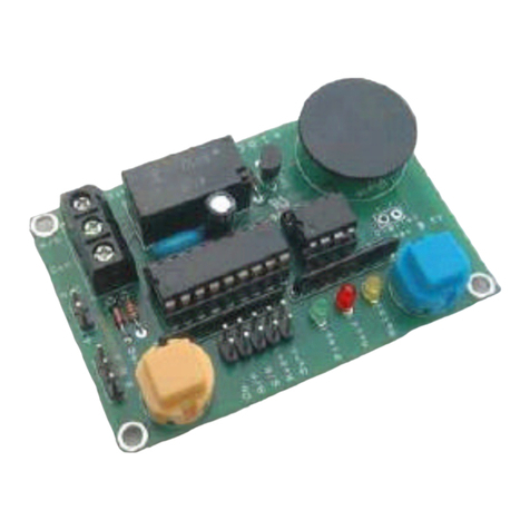
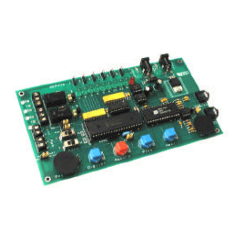
Wizard - VIII Board is pre-assembled and tested.
Regulated 9 Volt dc power supply @ 0.5 Amp
power supply required.
Board Size: 3-5/8" L x 3-7/8" W x 1/2" H
WIZARD - VIII BOARD
www.BPEsolutions.com
Board Size: 4" L x 4" W x 1/2"H
The Wizard - VIII Controller Board provides a
single channel, digital output combined with a 4 minute
duration sound chip.
The board incorporates such features as recorded
looping playback, variable delay between recorded
programmed routines, auto loop, auto start-up on
power start, a connection terminal for remote switch
activation by manual switch, PIR sensor, pressure pad,
etc, to activate playback routines.
Sound recording is direct to digital sound chip, and
can be done from a computer sound port, CD player or
any sound source with audio output connections.
Recording output sessions are built up on a
channel-by-channel basis - no complex programming
is needed or connection to a host computer to program
routines. All programming is easily done on-board the
controller through push button switches and LED
status indicators.
WIZARD - VIII BOARD FEATURES:
• 1 - selectable on-board relays ( 2 Amp @ 30 Volts dc ).
• Relays have insert wire terminal connection blocks.
• 1 - direct Digital control signal 0 - 4.5 Volts dc -10 mA connection pads, for hard wiring to board outputs.
• On-board potentiometer to determine the time delay between playback loops during automatic loop play,
fully adjustable between 0 and 65 seconds.
• On-board GO and DIGITAL control buttons.
• Record EEprom for recorded programming routines and Digital 4 minute Sound IC Chip.
• On-board AUTO-PLAY and LOOP-PLAY switches / jumpers.
• On-board Status LED's ( Green -Relay ON and Red - Recording ).
• Battery remote operation or wall power operation.
• Remote terminal block activation connection for manual start switch, pressure mat or PIR sensor.
• EEPROM - containing the programmed data, can be removed and copied to other Wizard - VIII boards.
• Synchronization output signal to activate other Wizard boards.
• Board is powered from regulated 9 Volts dc power supply or can be run from optional Remote Battery
operation for mobile setup.
• Power supply polarity protection on-board to prevent board electronics damages.
• Ability to share a common power connection when multiple device set-up is needed.
• REM - board trigger input with sensor H or L signal activation jumper.
• Many more unique features.
+
NC
NOC

Page 2
DIGITAL- On / Off -Button
Pressing the Digital button will activate the relay output as ON or OFF.
This is a momentary switch. ( Relay - Green LED will turn ON when Digital button is pressed )
GO / RECORD - Button
Replays a set of recorded relay, sound actions.
Starts and Stops the record mode ( Red LED will turn ON indicating recording )
A switch, sensor may be connected to the REM connection and this will function in the same way as the GO
Button
Press and release the GO button to start recording a routine. Press and release the Go - button to stop
recording. If the GO - button is held down and the PLAY slide switch is set to REC, when power is first
applied to the board, all relay memory will be erased. (Takes approximately 20 seconds).
PLAY / REC - Slide Switch
Selects either Playback or Record Mode.
SOUND / RELAY - Slide Switch
Selects either Sound or Relay Mode.
SYNC Terminal
Synchronizing connection for multiple board module operation. On-board terminal connection delivers a pulse
low signal (30 msec) at the start of playback and record event which may be used to trigger other Wizard
boards connected in a chain or master module - slave module setup. Sync output to Rem input of other boards.
REM Terminal
Used to trigger Wizard board by remote switch, sensor. Can also be jumped together for no-stop playback.
LOOP - SINGLE Jumper
To make the Wizard - VIII board play the recorded moves repeatedly, move the Jumper Block to the Loop
position. The recorded moves will start to play when the GO button is first pressed. There will be a pause at
the end of playing (determine by the position of the Delay control) after which the recorded action will start
again. In Single mode, playback will start once and wait for next GO or Sensor input to start.
DELAY - potentiometer.
Pause between playback loop option.
When the Wizard - VIII board is set to the LOOPposition, the length of the pause between repeated
playbacks may be set by rotating the on-board Delay control potentiometer.
Turn theDelay control counter clockwise (CCW) for the minimum delay (approximately 2 seconds and
clockwise for the maximum delay (approximately 65 seconds).
AUTO / ON - slide switch.
To make the Wizard - VIII board play the recorded moves repeatedly on power - ON or reset, move the switch
to the"ON" position. The recorded actions will start to play on any power-up.
Clearing Relay Memory to start a new program.
The PLAY / RECORD slide switch must be in the "REC" position.
The GO - button is held down during Power Up, and released after power is applied.
After the initial 20 seconds the board is now ready for new programming.
Clearing Sound Memory to start a new program.
The Audio recording chip cannot be bulk - erased. The audio track can only be replaced by re-recording a new
audio track over the old track or by recording a blank audio session.
NOTE:
The sound chip will not play any sound unless there is a stored relay / digital recording.
If you erase the relay digital recording then the sound chip will not play sound until you have
re-recorded a relay / digital program routine.
Board Functions:
+
NC
NOC

Page 3
Relay - NC, C, NO connections.
NC = Normally Closed position of the relay contacts ( Circuit is ON- will open circuit (OFF) when activated )
C = Common connection to relay contacts
NO = Normally Open position of the relay contacts ( Circuit is OFF- will close circuit (ON) when activated )
Green LED Status - Activates when the Relay is powered ON.
JP1 - Relay / Pin Output Jumpers. When this jumper is in place, the board will activate the on-board relay.
The relay is rated at 30 V @ 2Amp. When the jumper is removed, the relay is de-activated and the output pins
next to the jumper may be used as voltage drivers ( 0 Vdc and 4 Vdc @ 10mA). The pins are marked with
Plus (+) and Minus (-) for correct polarity connection. Use caution when connecting to the pins to observe
correct polarity (+ / - )
ON / OFF Power Switch
Turns ON and OFF power to the Wizard - VIII controller board.
When powering the board, a set of remote switch wires can be soldered to these holes for a more permanent
connection.
POWER - Wire Terminal
+ ( Plus ) and - ( Minus ) connections
When powering the board from a non 2.1 mm power connector supply, the power wires can be connected to
these terminals for a more permanent connection. Observe polarity + and - to prevent damaging the board.
Speaker Wire Terminal Block
Connect a small 4 to 32 Ohm - 1 watt speaker to the terminal for on-board sound chip amplification
playback. The on-board VOLUME potentiometer can be adjusted to control the audio output level for the
Speaker Terminal. Note this control does not adjust the Line Output Jack audio signal level.
Line Input Jack
Up to 4 minutes of audio may be stored in the on-board chip. The source for this is the line level signal.
Connect a Mono Audio cable from a sound source into the Line Input Jack. Input sensitivity = 320 MV P-P
for maximum recording volume.
Line Output Jack
The audio output from the sound board may be amplified by an external amplifier, by connecting an audio
cable to the Line Output jack or the two pin header and directly into a remote Audio Amplification System.
Note: The on-board amplifier is automatically disconnected when an audio jack plug is inserted into the Line
Out jack. The line output signal is approximately 2 V P-P at maximum recorded volume.
RECORDING TIMES: The maximum recording time is 4 minutes for the sound chip and 5 minutes for
the Digital / Relay - ON / Off action.
Example
1. Recording An Audio Track
Set the PLAY - REC slide switch to REC (Record) position.
Set the SOUND - RELAY slide switch to SOUND position.
Set the AUTO - ON slide switch to the AUTO position (Off)
Connect one end of an Audio (Mono) Cable to the Line Input jack and the other end to a Audio Source
(Computer sound port, CD Player, Stereo, Etc.)
Start the Audio Source (Computer, CD Player, Stereo, Etc.)
Press and Release the GObutton - the Red LED light will turn ON. (Recording sound into chip has
started)
Press and Release the GObutton to terminate the recording session when the audio is done - the Red LED
will turn OFF. The Digital / Relay will respond to the Digital button ON-OFF during recording.
NOTE: The sound chip will not playback any sound unless there is a stored relay / digital
recording. If you erase the relay digital recording then the sound chip will not playback sound
until you have re-recorded a relay / digital program routine.
+
NC
NOC
Board Functions:

Page 4
Example
2. Recording An Digital / Relay Track
Set the PLAY - REC slide switch to REC (Record) position.
Set the SOUND - RELAY slide switch to RELAY position.
Set the AUTO - ON slide switch to the AUTO position (Off)
Press and Release the GObutton - the Red LED light will turn ON.
Any recorded sounds will also start to playback.
Press and release the Digital button as needed. (All actions will be recorded)
The Green Relay LED will turn On and OFF as you activate the Digital Button.
( When Relay is ON, it will activate device connected to relay wire terminals, N.O, and C connections )
Press and Release the GObutton to terminate the recording session when done, or when the board has reached
it's maximum of 5 minutes. - the Red LED will turn OFFand the board will end automatically.
Example
3. Playback
Set the PLAY - REC slide switch to PLAY position.
Set the AUTO - ON slide switch to the AUTO position (Off)
Press and Release the GObutton to start playback, or trigger the REM terminal ( By switch, sensor)
Note: Playback will continue until the end of the recorded Digital / Relay recorded motion is reached
The audio track does not govern the length of playback. To hear the complete 4 - minutes of audio track,
record the Digital / Relay motion to it's full max record length. ( no relay action )
To set the playback to auto - startup, looping, wait delays, or consecutive playback, select and adjust the delay,
Auto, and REM ports to needed settings.
+
NC
NOC
I am trying to hear the audio that I just recorded?
The sound chip will not playback any sound unless there is a stored relay / digital recording.
If you erase the relay digital recording then the sound chip will not playback sound until you
have re-recorded a relay / digital program routine.
Problem / Hint Help Guide
Q
A
Q
A
I do not hear any sound from a small speaker connected to the speaker terminal block.?
The on-board amplifier is automatically disconnected when an audio jack plug is inserted
into the Line Out jack. Remove the Audio cable from the Line Out jack.
Q
A
How can I hear the sound being recorded to the sound chip when I connect a sound source to the Line
Input Jack?
Use a "Y" audio split cable. Connect one end of the "Y" split cable to the Line Input jack, on
board and the other end of the "Y" to a small remote speaker. When you connect the main
"Y" audio jack lead to the sound source, you will be able to hear and adjust the output audio
level going into the Input jack and Sound Chip.
Q
A
I am having trouble with audio?
Use a "Mono" cable.
Make sure that the sound source your using has at least 320 MV / P-P output for maximum recording
volume.

Page 5
Power Supply
The Wizard - VIII control board will work with power supplies between 9 and 12 Vdc @ 0.5 Amp.
A small 2.1 mm socket with center positive is built-on board for quick power connection.
Copyright © 2003 Blue Point Engineering , All Rights Reserved
Connector
Regulated
+ 9 Volt DC
+
-
Power - Wire Connection Block
Optional Power Connection
Regulated 9Vdc @ 0.5 Amp
Wizard - VIII Controller Board
Power Supply Overview
9 Vdc @ 0.5 Amp
+ Vdc
center
- Vdc
2.1 mm
Connector
Regulated
Power
- Vdc
outside
+ Vdc
center Red
Black
Wall Plug Power Supply
REGULATED 9 Vdc @ 0.5 Amp
Recommended
outside
Version 1.0
NC
NOC
2.1 mm
Connector
PC Board
Power ON / OFF Switch
OFF
ON Power ON LED

Phone (303) 651-3794
www.BPEsolutions.com
Blue Point Engineering
Custom Equipment, Unique Electronic Products
Copyright © 2003 Blue Point Engineering , All Rights Reserved Version 1.0
Page 6
+
Wizard - VIII Controller Board
Overview
Pin Header
Connection
0 / 4.5 Vdc output
+ -
NC
NOC
Line
Input
Line
Out
Speaker Wire
Terminal
(Audio Monitor)
Volume Control
(Speaker Terminal Only)
ON / OFF
Power
Switch
Optional
Power- Wire
Terminal
( + / - VDC)
Power- Jack
( 2.1 mm)
Relay
Relay ON
LED
Playback Delay
Sync Terminal
REM Terminal
Digital ON/ OFF Button
Auto Slide Switch - Auto / ON
Play / Record Slide Switch
PLAY / REC
Sound Relay Slide Switch
GO Button
Playback
Record
Start / Stop
Loop / Single
Playback Jumper
Loop Single
Loop Single
Power ON
LED
Recording
ON - LED
To remote Sound
Amplification System
From sound source
(CD player, Computer,
Stereo, Mic, Sound
source) Relay &
Relay Memory
EEprom
Sound Chip
Table of contents
Other Blue Point Engineering Controllers manuals
