manuals.online logo
Brands
  1. Home
  2. •
  3. Brands
  4. •
  5. Sub-Zero
  6. •
  7. Controllers
  8. •
  9. Sub-Zero CRC-2020 User manual

Sub-Zero CRC-2020 User manual

Other Sub-Zero Controllers manuals

Sub-Zero CRC-1001 User manual

Sub-Zero

Sub-Zero CRC-1001 User manual

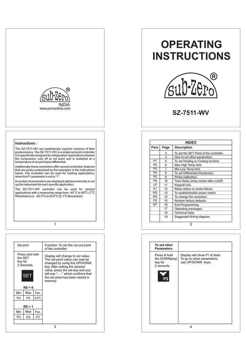
Sub-Zero SZ-7511-WV User manual

Sub-Zero

Sub-Zero SZ-7511-WV User manual

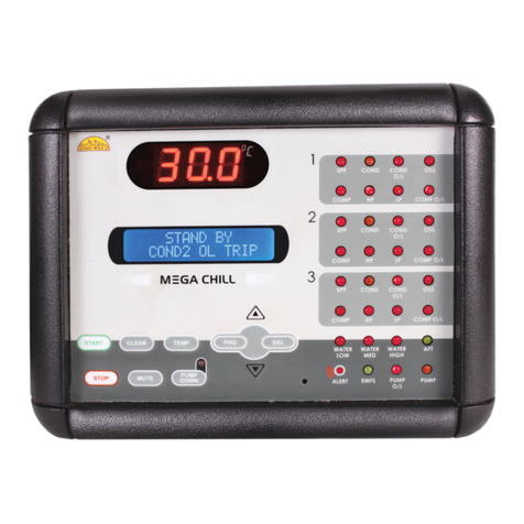
Sub-Zero Mega Chill-3Comp User manual

Sub-Zero

Sub-Zero Mega Chill-3Comp User manual

Sub-Zero Mega Chill User manual

Sub-Zero

Sub-Zero Mega Chill User manual

Sub-Zero Mega Chill User manual

Sub-Zero

Sub-Zero Mega Chill User manual

Sub-Zero PT244-T User manual

Sub-Zero

Sub-Zero PT244-T User manual

Sub-Zero SZ-CRC-1100A User manual

Sub-Zero

Sub-Zero SZ-CRC-1100A User manual

Sub-Zero SZ-7524-P User manual

Sub-Zero

Sub-Zero SZ-7524-P User manual

Sub-Zero NANOCHILL NC-120A User manual

Sub-Zero

Sub-Zero NANOCHILL NC-120A User manual

Sub-Zero CRC-2052 User manual

Sub-Zero

Sub-Zero CRC-2052 User manual

Sub-Zero CRC-1023 User manual

Sub-Zero

Sub-Zero CRC-1023 User manual

Popular Controllers manuals by other brands

Sunricher SR-ZV9003T3-RGBW-US Installation

Sunricher

Sunricher SR-ZV9003T3-RGBW-US Installation

Ksenia intro Installation and configuration manual

Ksenia

Ksenia intro Installation and configuration manual

Inovance CAN200 Series manual

Inovance

Inovance CAN200 Series manual

Gauzy LC6 FLEX Controller Installation and operation guide

Gauzy

Gauzy LC6 FLEX Controller Installation and operation guide

Viking SLP-1 Technical practice

Viking

Viking SLP-1 Technical practice

CKD KBX-30E-U Series instruction manual

CKD

CKD KBX-30E-U Series instruction manual

Sharp Energy Sun Flux User manual & installation guide

Sharp Energy

Sharp Energy Sun Flux User manual & installation guide

Yamaha RCX40 user manual

Yamaha

Yamaha RCX40 user manual

AB Quality PowerFlex 400 Frames D-H Service bulletin

AB Quality

AB Quality PowerFlex 400 Frames D-H Service bulletin

Yamaha MJC8 owner's manual

Yamaha

Yamaha MJC8 owner's manual

AL-KO ATC operating instructions

AL-KO

AL-KO ATC operating instructions

Savant SmartControl 2 Deployment guide

Savant

Savant SmartControl 2 Deployment guide

GameSir T3S user manual

GameSir

GameSir T3S user manual

Kostal inveor operating manual

Kostal

Kostal inveor operating manual

Emerson Yarway 20-55 Operating and safety instructions

Emerson

Emerson Yarway 20-55 Operating and safety instructions

CoCo ACM-LV24 Quick installation guide

CoCo

CoCo ACM-LV24 Quick installation guide

Brooks SLA5810/20 Installation and operation manual

Brooks

Brooks SLA5810/20 Installation and operation manual

SIGMA TEK SR 011 Technical manual

SIGMA TEK

SIGMA TEK SR 011 Technical manual

manuals.online logo
manuals.online logoBrands
  • About & Mission
  • Contact us
  • Privacy Policy
  • Terms and Conditions

Copyright 2025 Manuals.Online. All Rights Reserved.

AMP
CRC-2020
Index Index
01 02
Index Index
Introduction
Get to Know Your Controller
LED Indication.
4
7
Parameter List.
Key Introduction 5
3
Fault Messages. 6
DESCRIPTION
PARAMETER
Pg.
No.
To set the cut-out point of the controller.
SET POINT 8
DESCRIPTION
PARAMETER
Pg.
No.
Items Included. 4
8
To set other parameter 8
To set allowable high temperature limit.
To set allowable low temperature limit.
To set the differential for compressor
restart.
P2
P3
P4
9
9
10
To set probe calibration.P5 10
To set time delay between relay restart
time.
P6 10-11
To set duration of defrost.P7 11
To set defrost frequency.
To set power on defrost delay.
P8
P9
11
11
To enable / disable buzzer.BUZ 12
This parameter is used to set power on
delay for alarm.
AL 12
Under load limit for compressor current.C-UL 12
Over load limit for compressor current.C-OL 13
Current sensing delay.
C2 13
To enable or Disable HP sensing.
D0 13
To enable or disable LP sensing.
D1 14
Fault sensing logic.
D2 14
To set LP sensing delay.
To set reset mode for HP fault.
D3
D4
14
15
15
To set Compressor Relay status on
Probe Failure.
To set On cycle at room probe fail.
To set Off cycle at room probe fail.
To set Display at defrosting.
E1
TON
TOFF
E7
16
16
16
16
To set time delay to switch off the light .
To change password.
To view Compressor run Hours.
Clear Compressor Run Hours.
To set Unit ID.
LD
PW
CRH
CCRH
Unit ID
17
17
17
17
18
To activate Keypad Lock.
To enable/disable Power Switch.
To set display at power OFF mode.
LP
PO
PDIS
18
18-19
19
To restore default settings of the
controller.
FS 19
End of programming.
EP 19
Technical Data 20
Caution & Warranty
21
30-31
Suggested Wiring Diagram
DI-D
OPS
To select AUX or compressor thermal
trip digital I/P
To Enable / Disable Oil Pressure Switch
(OPS) I/P.
15
21-28
Instruction manual for VMRC-10/3
CRC-2020 CRC-2020
29
04
03
Introduction
Features:
The CRC-2020 is single set point cold room controller. The
Sub-Zero CRC-2020 is aesthetically superior versions of their
predecessors.
A series of “safety controls” (delay at start-up, minimum disable
time, minimum time between activation) protects the
compressors from close starts. In case of probe error or
temperature alarm, the instrument signals the event through
acoustic signal and by closing the relay contact. By pressing
the mute key, the buzzer is silenced.
A number of parameters are displayed alphanumerically to set
up the instrument for each specific function.
The CRC-2020 controller can be used for several applications
with a measuring range from
O O
-50.0 C to 50.0 C.
Computer Connectivity over RS485 and Remote
monitoring(Optional).
The controller controls the defrost in the system based on time
based where the compressor is stopped. It is also possible to
select the interval between defrosts and a maximum time out
after which the defrost is interrupted.
There are safety features which include shutting down the
system incase of a fault from a pressure control or similar
device.
Get to Know Your Controller
Items included
NO.
1.
2.
3.
4.
QTY
ITEMS
CONTROLLER
CATALOGUE
NTC SENSOR 5 METER
1
1
1
4
8 X 38 SCREW WITH RAWL PLUG
CRC-2020 CRC-2020
CRC-2020
R Y B
06
05 CRC-2020CRC-2020
Key Introduction
FLT LOG
Used to switch OFF/ON the controller.
Used to come mute the buzzer/Alarm & to exit any mode.
Used to increment/scroll in Program Mode.
When not in any mode if this key is pressed for 2 secs controller will
enter in fault log mode.
PRG
Used to enter into the Set mode. Also used as enter key if controller
is in Set mode/program mode.
Used to enter in manual defrost and to stop defrost if
defrosting is ON.
Used to decrement/scroll in Program mode.
Used to enter into the program mode.
Used to switch OFF/ON the light.
Used to enter into the Amp. mode where compressor current can
be viewed.
AMP
High temperature alarm for Room means, room temperature is
equal or above the set value of P2 parameter.
Low temperature alarm for Room means, room temperature is
equal or below the set value of P3 parameter.
Ht
Lt
Room temperature fail means, Room sensor not connected or
out of range.
PP
SPPR Fault.
Compressor over load fault.
SPPR
C-OL
Compressor under load fault.
C-UL
Fault Messages :
HP fault.
HP
Auxiliary fault / Compressor Thermal Fault .
LP fault.
LP
AUX / CTH
Door Open fault.
DO
OPS Oil Pressure Switch Fault.
08
07
Min: MINIMUM Max : MAXIMUM
Fact. Set : FACTORY SETTING(DEFAULT)
Sr.
No.
Parameter setting method
Description of parameters and functions.
Parameter
To set other parameter
Press & hold SET key for
2 seconds
Display will show ‘SET’ and scroll the
description of the parameter.
To go to other parameters, use UP /
DOWN keys.
SP To set the cut-out point of the controller.
Display will change to set value.
The set point value can now be changed by
using the UP/DOWN key. After desired
value, press the SET key & you will see “--”
which confirms that the set point has been
stored in memory.
01
To change Set Point parameter,
press the set key.
P3+0.5ºC P2-0.5ºC 0.0ºC
Range
Min Max Fact. Set
To set other parameter
Press & hold PRG key for
2 seconds
Display will show ‘P2’ and scroll the
description of the parameter.
To go to other parameters, use UP /
DOWN keys.
PRG
LED Indication
Messages Mode Discription
Comp. Relay On.
Comp. Relay Off.
Comp. Relay Timedelay.
Defrost On.
Defrost Off.
Defrost in Timedelay.
Alarm Relay On.
Alarm Relay Off.
Power Off.
Power On.
Light Relay On.
Light Relay Off.
R-phase present.
R-phase absent.
R
Y-phase present.
Y-phase absent.
Y
B-phase present.
B-phase absent.
B
On
Off
Flashing
On
Off
Flashing
On
Off
Off
On
On
Off
On
Off
On
Off
On
Off
CRC-2020 CRC-2020
10
Sr.
No.
Parameter setting method
Description of parameters and functions.
Parameter
01
P2
Parameter
Function : To set allowable high
temperature limit.
To change P2 parameter,
press the set key.
Use UP/DOWN key to set desired value.
Once set at a particular value, this will not
allow the set point to go above this
value and below P3 setting.
Example : Setting this parameter
0
at 50.0 C will not allow the set point to go
0
above 50.0 C also if the temperature
0
reaches 50.0 C, the display will show HT
(High Temperature). The alarm will be
ON. But at power on till the AL delay is
over controller will not generate HT Alarm.
SP+0.5ºC 50.0ºC 50.0ºC
Range
Min Max Fact. Set
(Message on Display)
09
Sr.
No.
Parameter setting method
Description of parameters and functions.
Parameter
02
P3
Parameter
Function : To set allowable low
temperature limit.
Use UP/DOWN key to set desired value.
Once set at a particular value, this will not
allow the set point to go below this value
and above P2 setting.
Example : Setting this parameter at
0
-50.0 C will not allow the set point to go
0
below -50.0 C also if the temperature
0
reaches -50.0 C, the display will show LT
(Low Temperature). The alarm will be ON.
To change parameter,
press the set key.
P3
-50.0ºC SP-0.5ºC -50.0ºC
Range
Min Max Fact. Set
(Message on Display)
Use UP/DOWN keys to set desired value.
Example(Cooling Mode) : If the set point
0
is set at 10.0 C and differential is set at
0
2.0 C, then when the system reaches
0
10.0 C, the comp. relay will cutout. Since
0
the differential is 2.0 C, the comp. Relay
0
will cutin at 12.0 C
0 0
(10.0 C + 2.0 C).
03
P4
Parameter
Function : To set the differential for
compressor restart.
To change P4
press the set key.
parameter,
0.5ºC 20.0ºC 2.0ºC
Range
Min Max Fact. Set
P5
Parameter
Use UP/DOWN keys to set desired value.
In time it may be possible that the display
may be offset by a degree or so.
To compensate for this error, you may
need to add or minus the degrees
required to achi eve t he co rrect
temperature.
Example : The temperature on the
O
display is 28.0 C, whereas the actual
O
temperature is 30.0 C. You will need to set
O
this parameter to 2.0 C, which means that
once out of the programming parameter,
the display will show the temperature
O O O
30.0 C (28.0 C + 2.0 C).
To change P5
press the set key.
parameter,
04
Function : To set probe calibration.
-10.0ºC 10.0ºC 0.0ºC
Range
Min Max Fact. Set
HT
LT Use UP/DOWN keys to set desired value.
This parameter is used to protect the fan
from restarting in a short period of time
and can be set between 0 to 20 minutes.
Example : If this parameter is set at 3
minutes, the compressor will cut off at
the set temperature, but will not restart
for a minimum of 3 minutes, even if the
differential is achieved earlier. This
P6
Parameter
To change P6
press the set key.
parameter,
05
Function : To set time delay between
relay restart time.
1 Min 20 Min 3 Min
Range
Min Max Fact. Set
CRC-2020 CRC-2020
12
11
Sr.
No.
Parameter setting method
Description of parameters and functions.
Parameter
parameter is good to protect the life of
the compressor when there are power
fluctuations and the compressor is
switched off and on within a few seconds.
Sr.
No.
Parameter setting method
Description of parameters and functions.
Parameter
P7
Parameter
06
Function : To set duration of defrost.
To change the P7 Parameter
parameter, press the set key.
Use UP/DOWN keys to set desired value.
0 Min 99 Min 30 Min
Range
Min Max Fact. Set
This is maximum amount of time allowed
for defrost. If set to 0, there will be no
defrost cycle.
Example : If P7 is set to 30 Mins and P8
parameter is set to 1 Hr. then after every 1
Hr defrosting will take place for 15 mins.
P8
Parameter
07
Function : To set defrost frequency.
To change the P8 Parameter
parameter, press the set key.
Use UP/DOWN keys to set desired value.
1 Hr 31 Hrs 6 Hr
Range
Min Max Fact. Set
This is the amount of time between two
defrost cycles.
Example : same as P7 parameter.
P9
Parameter
08
Function : To set power on defrost delay.
To change the P9 Parameter
parameter, press the set key.
Use UP/DOWN keys to set desired value.
0 Min 99 Min 30 Min
Range
Min Max Fact. Set
This is the amount of time at power on
after which defrosting will take place
once.
Example : If P9 parameter is 30 mins
then at power after 30 mins defrosting will
take place once.
BUZ
Parameter
09
Function : To enable / disable buzzer.
To change the BUZ Parameter
parameter, press the set key.
Use UP/DOWN keys to set desired value.
DIS ENB ENB
Range
Min Max Fact. Set
Example:
ENB : Buzzer enabled.
DIS : Buzzer disabled.
AL
Parameter
10
Function : This parameter is used to set
power on delay for alarm.
To change the AL Parameter
parameter, press the set key.
Use UP/DOWN keys to set desired value.
0 Min 99 Min 30 Min
Range
Min Max Fact. Set
Example : If you set this parameter to 30,
once the power is switched on, the alarm
will not activate for 30 minutes after the
power is switched on. This is most useful
to avoid the nuisance alarms when the
ambients are high when the machine is
switched on after a long time.
C-UL
Parameter
11
Function : Under load limit for compressor
current.
To change the C-UL parameter,
press the set key.
Use UP/DOWN keys to set desired value.
Example : If C-UL= 1.0A and compressor
current is less than 1.0A then and exists till
C2 current sensing delay then it is
registered as UL fault. Compressor will
get OFF on this fault. If after 3 retries
within 1 Hour current drawn is still less
than 1.0Amp the controller will trip the
compressor on fault and activate
respective alarm relay. Also display will
flash ‘C-UL’. Controller will go in manual
reset mode.
0.0A (C-OL
-1.0)A
1.0A
Range
Min Max Fact. Set
CRC-2020 CRC-2020
13 14
Sr.
No.
Parameter setting method
Description of parameters and functions.
Parameter
Sr.
No.
Parameter setting method
Description of parameters and functions.
Parameter
C-OL
Parameter
12
Function : Over load limit for compressor
current.
To change the C-OL parameter,
press the set key.
Use UP/DOWN keys to set desired value.
Example : If C-OL= 10 A and compressor
current is greater than 10 A then and exist
till C2 current sensing delay then C-OL
fault exists and flash on display.
Compressor will be tripped on this fault.
NOTE : According to the compressor
current, set Overload value.
(C-UL
+1.0) A
30.0A 10.0A
Range
Min Max Fact. Set
Use UP/DOWN keys to set desired value.
Example : If C2 = 5 sec then, any current
fault will be valid only when it exists for
more than 5 sec.
To change the C2 parameter,
press the set key.
C2
Parameter
13
Function : Current sensing delay.
5 Sec 60 Sec 5 Sec
Range
Min Max Fact. Set
Use UP/DOWN keys to set desired value.
Example :
If this parameter is set to
ENB : HP sensing is enabled.
DIS : HP sensing is disabled
Setting this parameter to disable will
ignore HP fault for compressor. If this
parameter is set to Enable then controller
will detect HP trip.
To change the D0 parameter,
press the set key.
D0
Parameter
14
Function : To enable or Disable HP
sensing.
DIS ENB ENB
Range
Min Max Fact. Set
Use UP/DOWN keys to set desired
value.
Example:
If this parameter is set to
ENB : LP sensing is enabled.
DIS : LP sensing is disabled.
To change D1
parameter, press the set key.
DIS ENB
D1
Parameter
15
ENB
Function : To enable or disable LP
sensing.
Range
Min Max Fact. Set
D2
Parameter
16
To change D2 parameter,
press the set key.
0V 230V
Function : Fault sensing logic.
0V
Use UP/DOWN keys to set desired
value.
0V : 0V at HP/LP/AUX input will be
sensed as fault and trip the
compressor.
230V : 230V at HP/LP/AUX input will be
sensed as fault and trip the
compressor.
Range
Min Max Fact. Set
Setting this parameter to disable will
ignore LP fault for compressor. If this
parameter is set to Enable then controller will
detect LP trip.
To change D3 parameter,
press the set key.
0 Sec
17
MinMin
Use UP/DOWN keys to set desired value.
Example : If this parameter is set to 30
sec, then LP fault will be sensed only
when it present continuously for 30 Secs.
180 Sec 30 Sec
D3
Parameter
Function : To set LP sensing delay.
Range
Max Fact. Set
Range
Max Fact. Set
18.0A
CRC-2020 CRC-2020
15 16
Sr.
No.
Parameter setting method
Description of parameters and functions.
Parameter
Sr.
No.
Parameter setting method
Description of parameters and functions.
Parameter
To change D4 parameter,
press the set key.
D4
Parameter
18
Function : To set reset mode for HP fault.
MAN AUTO AUTO
Range
Min Max Fact. Set
Range
Min Max Fact. Set
Use UP/DOWN keys to set desired
value.
MAN : Manual Mode.
AUTO : Auto mode.
To change E1 parameter,
press the set key.
E1
Parameter
21
Range
Min Max Fact. Set
Range
Min Max Fact. Set
When set to
ON : Relay will stay ON.
CYC : Relay performs a duty cycle of
as per TON & TOFF .
OFF : Relay will stay OFF.
ON OFF CYC
Function : To set Compressor Relay
status on Probe Failure.
Use UP/DOWN keys to set desired
value.
To change TON parameter,
press the set key.
TOFF
Parameter
23
Range
Min Max Fact. Set
Range
Min Max Fact. Set
At room probe fail condition when E1
parameter is selected as 'CYC' then the
Off cycle is specified by Ton parameter.
1 Min 30 Min 4 Min
Function : To set Off cycle at room probe
fail.
Use UP/DOWN keys to set desired
value.
E7
Parameter
Use UP/DOWN keys to set desired
value.
TEMP : At defrosting temperature
will be dispalyed.
DEFR : At Defrosting 'Defrost ON'
will scroll.
24
Function : To set Display at defrosting.
To change E7 parameter,
press the SET key.
TEMP DEFR TEMP
Range
Min Max Fact. Set
Range
Min Max Fact. Set
DI-D
Parameter
19
Function : To select AUX or compressor
thermal trip digital I/P
To change the DI Parameter
parameter, press the set key.
Use UP/DOWN keys to set desired
value.
If Selected as “AUX” then at fault it will
display "AUX” on display.
If Selected as “CTH” then at fault it will
display “CTH”.
Range
Min Max Fact. Set
AUX CTH AUX
OPS
Parameter
20
Function : To Enable / Disable OPS I/P.
To change the OPS Parameter
parameter, press the set key.
Use UP/DOWN keys to set desired
value.
ENB : OPS I/P is enabled.
DIS : OPS I/P is disabled.
Range
Min Max Fact. Set
DIS ENB ENB
If this parameter set to “MAN” mode HP
fault will be cleared only after pressing
reset key for 2 seconds.
If this parameter is set to “AUTO” mode
HP fault will be cleared automatically
when it is healthy.
To change TON parameter,
press the set key.
TON
Parameter
22
Range
Min Max Fact. Set
Range
Min Max Fact. Set
At room probe fail condition when E1
parameter is selected as 'CYC' then the
on cycle is specified by Ton parameter.
1 Min 30 Min 10 Min
Function : To set On cycle at room
probe fail.
Use UP/DOWN keys to set desired
value.
CRC-2020 CRC-2020
18
17
Example : If this parameter is set to 7 mins
then, when light is switched on after 7 mins
it will be switch off automatically.
LD
Parameter
Use UP/DOWN keys to set desired value.
This parameter is used set the time delay
to automatically switch off the light. If LD is
set to 0 then this parameter is disabled.
25
Function : To set time delay to switch off
the light .
To change LD parameter,
press the SET key.
0 Min 30 Min 7 Min
Range
Min Max Fact. Set
Range
Min Max Fact. Set
Sr.
No.
Parameter setting method
Description of parameters and functions.
Parameter
Sr.
No.
Parameter setting method
Description of parameters and functions.
Parameter
09999 0000
To change the PW parameter,
press the set key.
PW
Parameter
26
Function : To change password.
Use UP/DOWN key to change the
password.
User can enter into program mode
only if correct password is entered. If the
password is wrong it will show ‘INVALID
PASSWORD’.
Range
Min Max Fact. Set
Range
Min Max Fact. Set
CRH
Parameter
27
Function : To view Compressor run Hours.
It will display compressor run hours. It's
a read only parameter.
ID
Parameter
This parameter is used to set the Unit ID
of the device.
29
Function : To set Unit ID.
To change Unit ID
parameter, press the SET key.
1 240 -
Range
Min Max Fact. Set
Range
Min Max Fact. Set
NO YES NO
CCRH
28
Function : Clear Compressor Run
Hours.
If this parameter is set to ‘YES’
compressor run hours (CRH) are
cleared.
Range
Min Max Fact. Set
Range
Min Max Fact. Set
LP
30
To change LP parameter,
press the set key.
NO YES NO
Function: To activate Keypad Lock.
This parameter can lock the keypad so
that tempering is not possible by by-
standers.
NO : deactivates keypad lock.
YES : activates keypad lock.
On activation, all the parameters can only
be viewed, but not modified.
If the keypad is locked “LOCK” message
will be displayed..
Range
Min Max Fact. Set
Range
Min Max Fact. Set
DIS ENB DIS
To change PO parameter,
press the SET key.
PO
Parameter
Function : To enable/disable Power
Switch.
Use UP/DOWN keys to get desired
value & press SET key to confirm.
DIS : Disable power switch
ENB : Enables power switch
23
31
Range
Min Max Fact. Set
Range
Min Max Fact. Set
Controller has power switch, which if
enable puts controller in active or stand by
state.
If press foe 2 seconds controller will go in
stand by state.
if press for 2 seconds controller will go in
stand by mode, display will be as per
“PDIS” parameter.
To again switch to ACTIVE WORKING
CRC-2020 CRC-2020