Blue Sky Network SKYLINK User manual

Any operation. Any asset. Anywhere. SkyLink Installation Guide v1.10
Page 2of 29 © 2021 Blue Sky Network, All Rights Reserved
SkyLink
Installation Guide
Version 1.9
Part Number: SL10001

SkyLink Installation Guide v1.10
Page 3of 29 © 2021 Blue Sky Network, All Rights Reserved
NOTICE
This guide is published and copyrighted by Blue Sky Network (BSN). All information and specifications in
this document are subject to change without notice. Nothing in this document is intended to create addi-
tional or separate warranties or guarantees.
Blue Sky Network, 5353 Mission Center Rd. #222, San Diego, CA 92108
Phone: +1 858-551-3894 | Fax: +1 858-225-0794
Email: support@blueskynetwork.com | Website: www.blueskynetwork.com
© 2021 Blue Sky Network, All Rights Reserved

Any operation. Any asset. Anywhere. SkyLink Installation Guide v1.10
Page 4of 29 © 2021 Blue Sky Network, All Rights Reserved
REVISION HISTORY
Date
Ver.
By
Description
13 April 2021
0.0
MZ
Initial Draft
30 April 2021
1.0
MZ
Final Version Release
17 May 2021
1.1
MZ
Updated terminal/antenna mounting sections
24 June 2021
1.2
MZ
Changed mounting renderings; added note about SIM cards
14 July 2021
1.3
MZ
Added aviation antenna information/diagram
28 July 2021
1.4
MZ
Included FXO/FXS adapter information
25 Aug 2021
1.5
MZ
Added SCAN antenna information; edited antenna location
suggestions table
1 Sept 2021
1.6
MZ
Included mention of SkyLink 7100 Install Guide; removed antenna
location suggestions table; made corrections based on feedback
9 Sept 2021
1.7
MZ
Added info for antenna location suggestions
14 Sept 2021
1.8
MZ
Updated MARUWA antenna non-direct connection numbers
28 Sept 2021
1.9
MZ
Added note to Step 4: Attach Adapters
15 Oct 2021
1.10
MZ
Added SkyLink DC Pigtail info; edited wording in several sections

SkyLink Installation Guide v1.10
Page 5of 29 © 2021 Blue Sky Network, All Rights Reserved
TABLE OF CONTENTS
Notice..............................................................................................................................3
Revision History..............................................................................................................4
Introduction ..................................................................................................................... 7
About SkyLink.........................................................................................................................................7
Installation Components ........................................................................................................................7
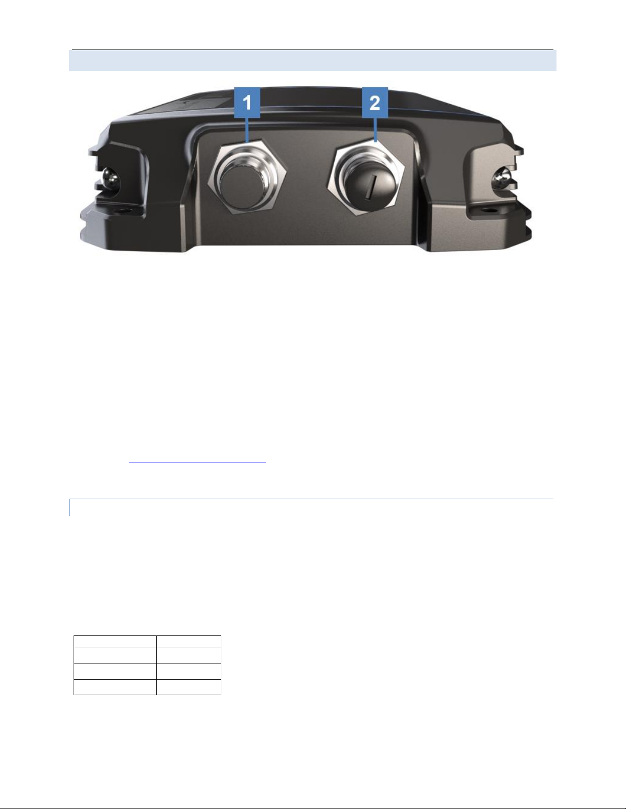
Top Panel Description ............................................................................................................................8
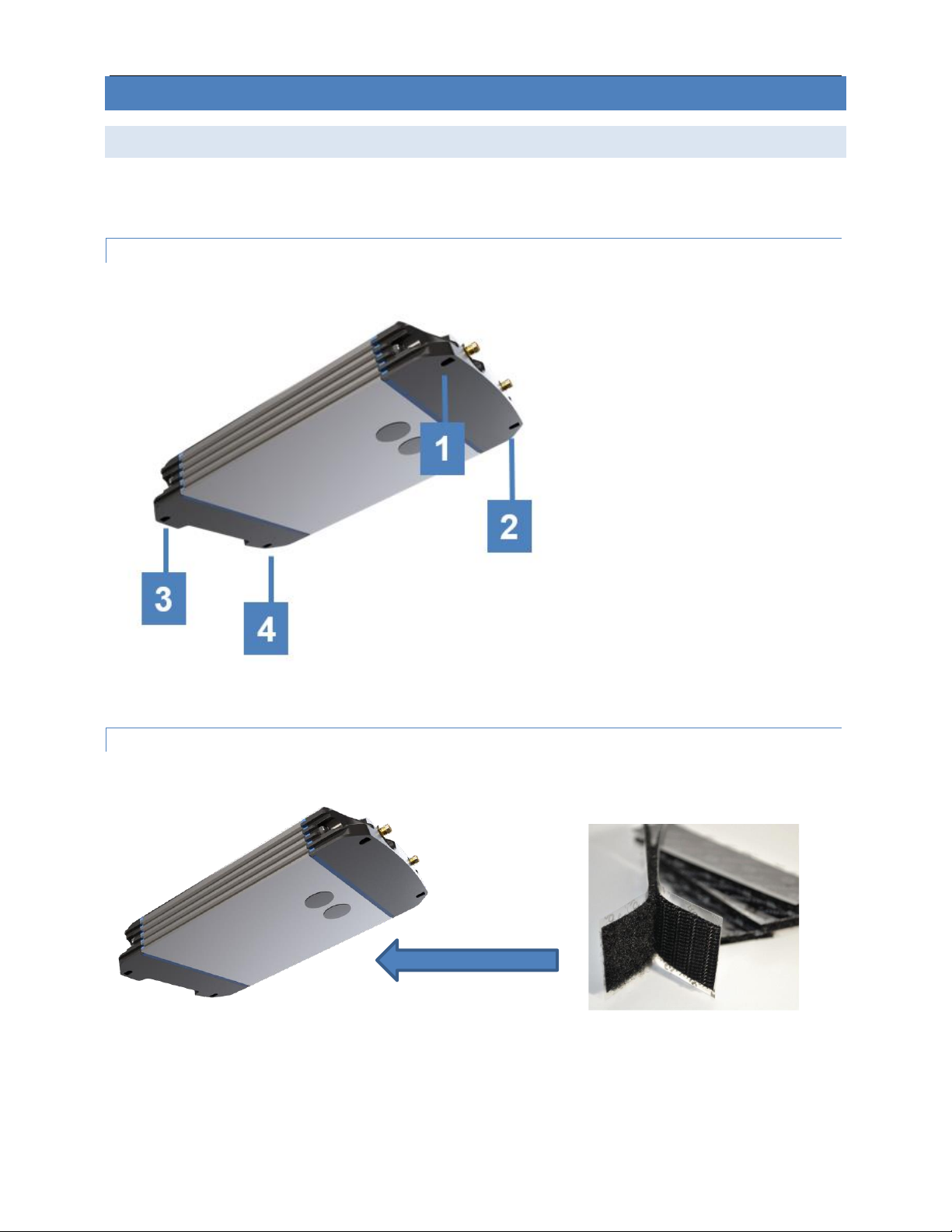
Bottom Panel Description......................................................................................................................9
SkyLink DC Pigtail Harness ...........................................................................................................9
Back Panel Description ........................................................................................................................10
Mounting & Installation.................................................................................................. 11
Mounting................................................................................................................................................11
Mounting the Unit................................................................................................................................11
Mounting with Adhesive ......................................................................................................................11
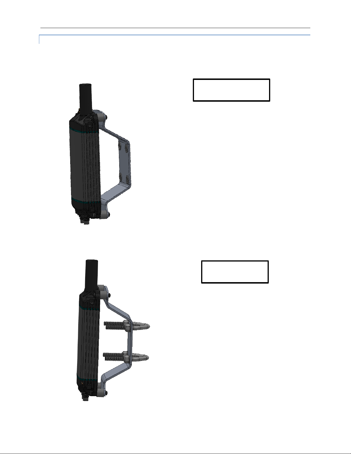
Mounting with SkyLink Mounting Bracket ...........................................................................................12
Other Installation Equipment...............................................................................................................13
Location Requirements........................................................................................................................14
Antennas.............................................................................................................................................14
SkyLink Terminal.................................................................................................................................14
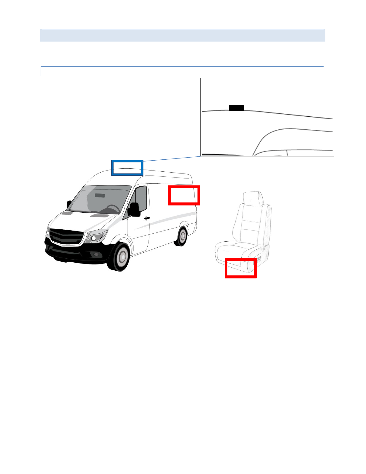
Location Suggestions...........................................................................................................................15
Vehicle.................................................................................................................................................15
Ship.....................................................................................................................................................16
Building................................................................................................................................................17
Aircraft/UAV.........................................................................................................................................18
Equipment Setup...........................................................................................................19
Step 1 –Install Cellular & Iridium SIM Cards .....................................................................................19
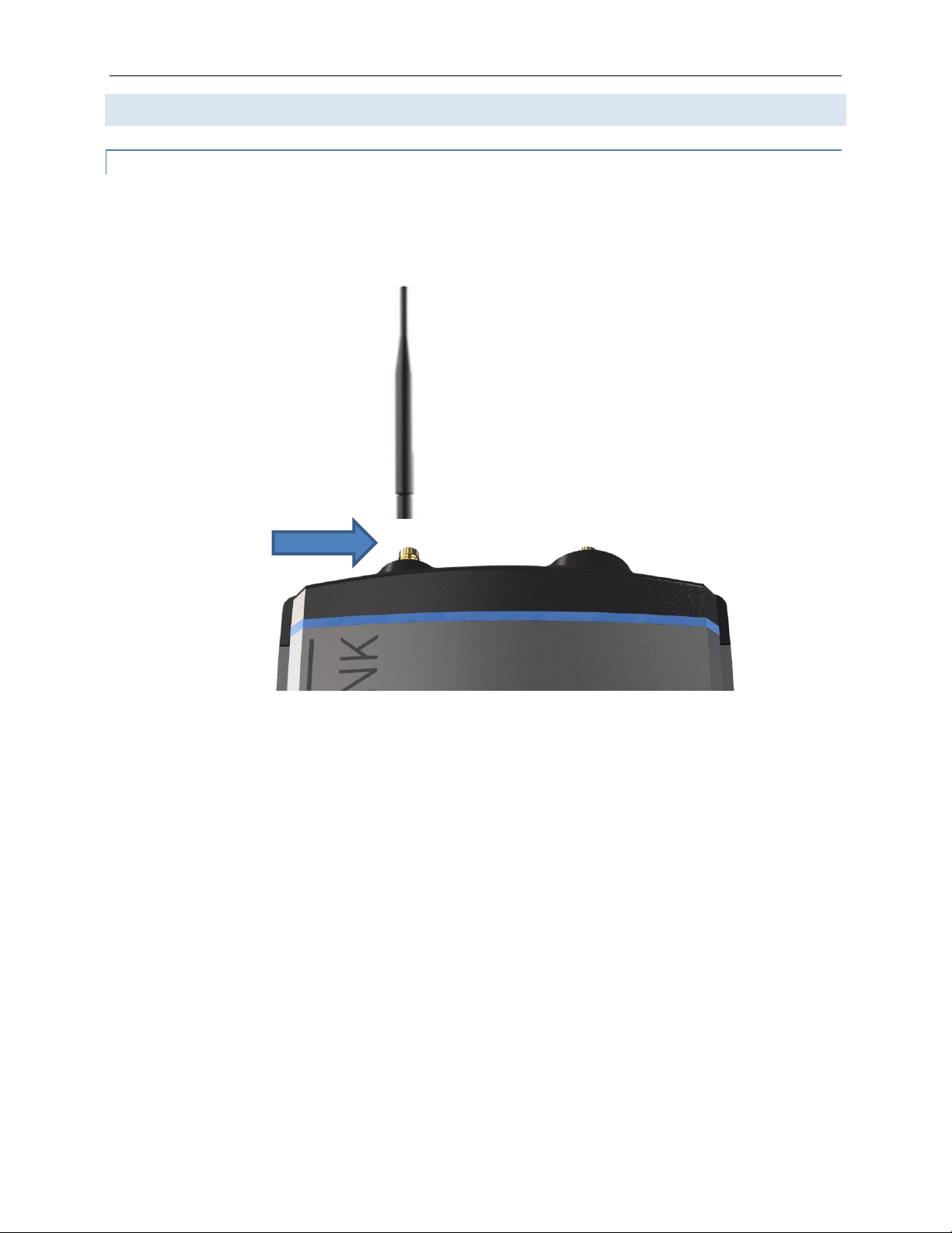
Step 2 –Attach Cellular & Iridium Antennas......................................................................................20
Cellular Antenna..................................................................................................................................20
Iridium Antennas .................................................................................................................................21

Any operation. Any asset. Anywhere. SkyLink Installation Guide v1.10
Page 6of 29 © 2021 Blue Sky Network, All Rights Reserved
Antenna Requirements .......................................................................................................................23
Step 3 –Attach Power ..........................................................................................................................24
Confirm Unit Status ..............................................................................................................................24
Power Off Unit .......................................................................................................................................24
Step 4 –Attach Adapters......................................................................................................................25
Step 5 –Complete Setup......................................................................................................................25
Appendix A - Troubleshooting....................................................................................... 26
Appendix B –Cable Diagrams......................................................................................27
Support.......................................................................................................................... 29

SkyLink Installation Guide v1.10
Page 7of 29 © 2021 Blue Sky Network, All Rights Reserved
INTRODUCTION
This installation guide demonstrates the process of mounting SkyLink to multiple fixed and non-fixed
assets, including a vehicle, ship, and/or building, among other rigid objects.
About SkyLink
SkyLink Cloud Services is a performance-driven, cloud-based analytics platform for remote, mobile, and
global operations. Leveraging Iridium’s satellite technology and local GSM/LTE networks, SkyLink is a
powerful dual-mode data management solution unlike any other.
This small-form, multi-stack hardware is designed for any fixed-mount, portable, or mobile application and
offers a range of service configurations for mission-focused safety, efficiency, versatility, and affordability.
The device can also be utilized with a variety of adapters and accessories to provide the preferred
configuration for each user. It is both IP65 Certified and FCC Part 15 & 25 Certified.
Installation Components
Installation components are based on the desired configuration for each unit; the list below describes
some of the most common components available in a kit or purchased. All adapter assemblies come with
a length of cable that is acceptable for typical installations. If a longer length is needed, you can purchase
an extender offered in multiple lengths.
•Dual Mode Data Gateway
•One of the following Iridium-approved Antennas:
oMARUWA –MHL-1621C
oHigh-Profile Maxtena –M1621HCT-HP
oLow-Profile Maxtena –M1621HCT-LP-SM; M1621HCT-LP-MM
oSensor Systems –S67-1575-414
oSCAN –65020-000
•SkyLink Mounting Bracket
oSelf-assembly kit
oPole Mount (optional)
•One of the following Power Adapters:
o12V Cigarette Lighter Adapter
o12V DC Power Adapter with Ignition Sense
oPOE Injector (self-assembly kit)
oAC/DC Power Supply (self-assembly kit)
•1’ Pigtail Ethernet Adapter
•6’ Ethernet Cable (longer length options available)
Please contact us for more information about available accessories and installation kits.

Any operation. Any asset. Anywhere. SkyLink Installation Guide v1.10
Page 8of 29 © 2021 Blue Sky Network, All Rights Reserved
Top Panel Description
The top panel contains a power LED indicator and 2 connectors for an Iridium and cellular antenna. The
descriptions below reference the photo above in accordance with the numerical value.
1. Iridium Antenna Connector
•Furthest connector from power LED indicator
•“IRI” etched into connector recess
2. Power LED Light
•Green = Initial Power On
•Red = Unit in Bootloader Mode
•Blue Blink = OS is Booting
•Blue Steady = Device is Ready
•Red Blink = Iridium Firmware Upgrade
•Blue Blink = SkyLink Firmware Upgrade
3. Cellular Antenna Connector
•Closest connector to power LED indicator
1
6
1
1
1
4
7
3

SkyLink Installation Guide v1.10
Page 9of 29 © 2021 Blue Sky Network, All Rights Reserved
Bottom Panel Description
The bottom panel contains a power port and a connectivity port that connects to multiple adapters. The
descriptions below reference the photo above in accordance with the numerical value.
NOTE: See Appendix B –Cable Diagrams for information regarding cable construction requirements.
SkyLink DC Pigtail Harness
This is the cable you receive if you request the currently labeled ‘SL100-IS, SkyLink 10’ Power Interface
Cable with QuickPosition (QPos).’ Below are the specs.
OPERATING PARAMETERS
Electrical
•External power:
o10-34 VDC (12V nominal power)
oPOE
•Power consumption
Function
Color
+Vin
Brown
GND
Green
SOS
White
1. Power Port
•Connects to the following adapters: 12V Cigarette
Lighter, 12V DC Power Supply, POE Injector, or AC/DC
Power Adapter
•Remove connector cap before attaching cable
2. Connectivity Port
•Connects to USB and RS232 adapters
•Remove connector cap before attaching adapter

Any operation. Any asset. Anywhere. SkyLink Installation Guide v1.10
Page 10 of 29 © 2021 Blue Sky Network, All Rights Reserved
Back Panel Description
The back panel of the unit contains a label with the following information:
•Model series number
•Part number
•Product serial number
•Iridium IMEI
•WiFi SSID and password
•Required certification notifications
•Power and mechanical specifications
•Scannable QR code to access device WiFi

SkyLink Installation Guide v1.10
Page 11 of 29 © 2021 Blue Sky Network, All Rights Reserved
MOUNTING & INSTALLATION
Mounting
The SkyLink device should be securely fastened to a rigid object to ensure optimal functionality. There
are three recommended methods for securing the terminal:
MOUNTING THE UNIT
All four corners of the device contain holes that can be used to affix the unit via straps, ties, or bolts.
MOUNTING WITH ADHESIVE
An adhesive (e.g., Velcro) can be placed on the back panel of the unit and attached to a rigid object.

Any operation. Any asset. Anywhere. SkyLink Installation Guide v1.10
Page 12 of 29 © 2021 Blue Sky Network, All Rights Reserved
MOUNTING WITH SKYLINK MOUNTING BRACKET
A universal mounting bracket with vibration dampening is included with your purchase of SkyLink,
allowing for the unit to be securely anchored to a fixed structure such as a wall. An optional pole mount
can also be purchased with the kit.
•For installation on wall,
panel, boat, truck
•Use wall anchors (4) in
2” x 2” pattern
Optional Pole Mount
SkyLink Mounting Bracket
•For vertical pole mount
installation (shown). Use
V-bolts (4) horizontally in
2” x 2” pattern
•For horizontal pole
mount installation (not
shown). Use V-bolts (4)
vertically in 2” x 2”
pattern

SkyLink Installation Guide v1.10
Page 13 of 29 © 2021 Blue Sky Network, All Rights Reserved
Other Installation Equipment
In addition to the equipment described above, the following may be useful to have during installation:
•Screwdriver & Socket Set

Any operation. Any asset. Anywhere. SkyLink Installation Guide v1.10
Page 14 of 29 © 2021 Blue Sky Network, All Rights Reserved
Location Requirements
The following must be observed when installing the SkyLink terminal and antennas:
ANTENNAS
NOTE: Certus-certified antennas for SkyLink are required. See the Antenna Requirements section for a
list of approved antennas.
The Iridium Certus Maxtena HP, SCAN, and MARUWA antennas are designed to be ground‐plane
independent and are certified for use 1m above the ground plane and should be mounted as such. Other
antennas such as Maxtena LP and Sensor Systems are designed to be ground-plane mounted, but their
certification is pending the antenna test data approval.
NOTE: To avoid exposure to antenna radiation, personnel should maintain a safe distance of 30 cm.
(11.8 in.) minimum from the antenna while the unit is operating.
•The antenna should be mounted in an area that prevents close exposure to its radiation.
•The antennas should be mounted with an unobstructed, clear view of the sky to avoid connection
and/or data speed issues.
•When possible, distance antennas from large metallic objects in the field of view.
•Place antennas as far away from other antennas (e.g., radar, magnetic compasses, HF
antennas) as possible to avoid interference.
SKYLINK TERMINAL
•The terminal should be securely fastened to the rigid object to ensure proper antenna and device
functioning.
•The terminal should not be placed in a location where it may become a hazard to the asset during
operation (e.g., placing the unit in a location that prevents free operation of gear selector, steering
wheel, or airbags in a vehicle) or in the event of a crash.
•Care should be taken to route cabling and wires through locations where they will not be
damaged by operator use of the asset (e.g., routing cables through driver footwell in a vehicle).

SkyLink Installation Guide v1.10
Page 15 of 29 © 2021 Blue Sky Network, All Rights Reserved
Antenna
•On roof of vehicle
NOTE: No ground plane is
required for Maxtena
antennas per antenna
manufacturer.
Location Suggestions
For the following diagrams, location suggestions for SkyLink are in RED and for the antenna in BLUE.
Each section also includes a brief description of the location suggestions.
VEHICLE
SkyLink
•Under driver or
passenger seat
•In trunk of vehicle

Any operation. Any asset. Anywhere. SkyLink Installation Guide v1.10
Page 16 of 29 © 2021 Blue Sky Network, All Rights Reserved
SHIP
SkyLink
•In bridge of ship
•On pole mount attached to mast
Antenna
•On mast
NOTE: The following must be observed
when mounting the antenna on a ship:
oAntennas should be placed as far away
from other antennas (e.g., radar,
magnetic compasses) as possible.
oIf mounting to a metal mast, the antenna
should be placed above it; otherwise, it
should be mounted to a wood or RF
transparent fiberglass mast.
oA clear view of +/-22⁰below the
horizontal plan is needed to provide full
functionality under extreme roll
conditions.
oA clear view of +/-2⁰below the horizontal
plan is needed to provide full
functionality under extreme pitch
conditions.

SkyLink Installation Guide v1.10
Page 17 of 29 © 2021 Blue Sky Network, All Rights Reserved
BUILDING
SkyLink
•On roof
NOTE: The terminal
should not be placed in
a room when using the
MARUWA antenna while
it is directly connected to
the terminal.
Antenna
•On roof
NOTE: Ensure that the
antenna is placed in an
unobstructed, full view of the
sky to mitigate connectivity
and/or data speed issues.

Any operation. Any asset. Anywhere. SkyLink Installation Guide v1.10
Page 18 of 29 © 2021 Blue Sky Network, All Rights Reserved
AIRCRAFT/UAV
NOTE: For more detailed information, please see the SkyLink 7100 Installation Guide.
SkyLink
•Installed internally
Antenna
•On fuselage

SkyLink Installation Guide v1.10
Page 19 of 29 © 2021 Blue Sky Network, All Rights Reserved
EQUIPMENT SETUP
Step 1 –Install Cellular & Iridium SIM Cards
NOTE: If you purchased your SkyLink device through Blue Sky Network, the unit will come with cellular
and Iridium SIM cards already installed.
To install your cellular and Iridium SIM cards:
1. Carefully remove the entire bottom panel of the unit by unscrewing the Phillips screw on each
side of the panel.
2. Insert SIM cards located behind connectivity port, taking care to ensure wires remain tucked in.
NOTE: A micro SD slot is also present behind the connectivity port. Ensure that the SIM
cards are placed into the correct holders and not the micro SD slot. If the device does not
work after installing the SIM cards, they may be in the wrong slots.
3. Re-attach bottom panel by re-screwing Phillips screws.

Any operation. Any asset. Anywhere. SkyLink Installation Guide v1.10
Page 20 of 29 © 2021 Blue Sky Network, All Rights Reserved
Step 2 –Attach Cellular & Iridium Antennas
CELLULAR ANTENNA
The SkyLink device uses an LTE extender antenna that connects directly to the cellular antenna
connector located on the top panel of the unit.
Other manuals for SKYLINK
5
Table of contents
Other Blue Sky Network Automobile Accessories manuals
Popular Automobile Accessories manuals by other brands

Whelen Engineering Company
Whelen Engineering Company LINZ6 installation guide

Kargo Master
Kargo Master 30070 installation guide

ULTIMATE SPEED
ULTIMATE SPEED UASB 12 A1 operating instructions

Jaeger
Jaeger 21270525J Fitting instructions

Mister EV
Mister EV MAXICHARGER User manual and safety instruction

Parrot
Parrot CK 3000 Evolution user guide

Mont Blanc
Mont Blanc FK 45 Fitting instructions

AMP Research
AMP Research PowerStep 77126-01A installation guide

TrailFX
TrailFX FX3018 manual

Fiamma
Fiamma CARRY-BIKE Installation and usage instructions

Whelen Engineering Company
Whelen Engineering Company 600 Series installation guide

DVB
DVB CMBR-01 installation manual