Blue Sky Network HawkEye 5500 User manual

HawkEye 5500
Install Guide
Version 3.4
BSN-300503

HawkEye 5500 Installation Guide - 6/23/2020 Notice
Page 2 of 37 © 2020 Blue Sky Network, All Right Reserved.

HawkEye 5500 Installation Guide - 6/23/2020 Notice
Page 3 of 37 © 2020 Blue Sky Network, All Right Reserved.
NOTICE
This guide is published and copyrighted by Blue Sky Network (BSN). All information and specifications in
this document are subject to change without notice. Nothing in this document is intended to create addi-
tional or separate warranties or guarantees.
Blue Sky Network, 5333 Mission Center Rd. #220, San Diego, CA 92108
Phone: +1 858-551-3894 | Fax: +1 858-225-0794
E: support@blueskynetwork.com | W: www.blueskynetwork.com
© 2020 Blue Sky Network, All Right Reserved.

HawkEye 5500 Installation Guide - 6/23/2020 Revision History
Page 4 of 37 © 2020 Blue Sky Network, All Right Reserved.
REVISION HISTORY
Date Rev. By Description
28-Jan-2020 1 CR Initial Release
15-Feb-2020 1.1 CR Update diagnostic section to match new commands
17-Feb-2020 3.0 CR Added wiring diagrams to appendix C
18-Feb-2020 3.1 CR Added photos and expanded installation requirements
15-Jun-2020 3.2 CR Updated wiring diagrams
16-Jun-2020 3.3 CR Changed behavior of waypoint LED
23-Jun-2020 3.4 CR Grammar corrections, added note about SOS pins, led behavior

HawkEye 5500 Installation Guide - 6/23/2020 Revision History
Page 5 of 37 © 2020 Blue Sky Network, All Right Reserved.
TABLE OF CONTENTS
Notice .............................................................................................................................. 3
Revision History .............................................................................................................. 4
Introduction ..................................................................................................................... 8
HawkEye 5500 .......................................................................................................................................... 8
Installation components ............................................................................................................................ 8
Extending Wiring Assemblies ................................................................................................................ 9
Rear Panel Description ........................................................................................................................... 10
Control Panel Description ....................................................................................................................... 11
Powering unit on via front pannel ........................................................................................................ 11
Sending a waypoint ............................................................................................................................. 11
Activating / Deactivating Emergency via front pannel ......................................................................... 11
Bottom Panel Description ........................................................................................................................ 12
Mounting & Installation .................................................................................................. 13
Installation Equipment ............................................................................................................................. 13
Location Requirements ........................................................................................................................... 14
Location Suggestions .............................................................................................................................. 14
Mounting.................................................................................................................................................. 14
Mounting with Just Unit ....................................................................................................................... 15
Mounting with Bracket ......................................................................................................................... 15
Installation Procedure .................................................................................................... 16
Step 1 - Install Battery & SIM .................................................................................................................. 16
Step 2 – Attach Power ............................................................................................................................ 17
PIN 1 ................................................................................................................................................... 17
PIN 2 ................................................................................................................................................... 17
PIN 3 ................................................................................................................................................... 17
Step 3 – Attach Antennas ....................................................................................................................... 18

HawkEye 5500 Installation Guide - 6/23/2020 Revision History
Page 6 of 37 © 2020 Blue Sky Network, All Right Reserved.
Tamper Indicator ................................................................................................................................. 18
External Antenna requirements........................................................................................................... 18
Iridium & GPS Antenna ....................................................................................................................... 19
Cellular Antenna .................................................................................................................................. 19
Step 4 – OBD Vehicle BUS Integration ................................................................................................... 20
Passenger vehicles ............................................................................................................................. 20
Commercial Vehicles .......................................................................................................................... 20
Step 5 – Install The Emergency Switch .................................................................................................. 21
Step 6 – Digitial & Analog Input/OUTPUT & 1-Wire & RS-232 ............................................................... 21
Step 7 – Attach Speaker Output ............................................................................................................. 21
First Power On Procedure ............................................................................................. 22
Activate Unit ............................................................................................................................................ 22
Power On Unit ......................................................................................................................................... 22
Configure Unit ......................................................................................................................................... 23
Confirm Unit Status ................................................................................................................................. 23
Power OFF Unit ...................................................................................................................................... 23
Replacing the SIM ......................................................................................................... 24
Configure cellular settings ....................................................................................................................... 24
Replacing or Removing the Battery ............................................................................... 25
Appendix A - FAQ ......................................................................................................... 26
Appendix B – Troubleshooting ...................................................................................... 27
DIAGNOSTIC TESTS ............................................................................................................................. 27
Perform a Full system test .................................................................................................................. 27
READ DIAGNOSTIC SYSTEM INFORMATION..................................................................................... 27
Connecting to BT command server .................................................................................................... 27
Sending SMS commands .................................................................................................................... 27
Issuing commands .............................................................................................................................. 27

HawkEye 5500 Installation Guide - 6/23/2020 Revision History
Page 7 of 37 © 2020 Blue Sky Network, All Right Reserved.
Appendix C – Cable Diagrams ...................................................................................... 29
Support .......................................................................................................................... 36

HawkEye 5500 Installation Guide - 6/23/2020 Introduction
Page 8 of 37 © 2020 Blue Sky Network, All Right Reserved.
INTRODUCTION
This installation guide covers the process to installing the HawkEye 5500 on a vehicle.
HAWKEYE 5500
The HawkEye 5500 is a dual-mode tracking, telemetry, and communication system designed to be installed
in vehicles. The dual-mode tracking capability enables the unit to switch back and forth between 2G/3G/LTE
cellular and Iridium satellite networks for uninterrupted tracking coverage. By utilizing the OBDII port on the
vehicle, the unit can also collect telemetry for transmission to the SkyRouter platform. The unit can also be
utilized with a variety of accessories and antenna kits in order to provide the preferred configuration for
each user.
INSTALLATION COMPONENTS
The list of components for installation are based on the desired configuration for each unit. Parts may be
purchased separately, and custom cable lengths can be specified during ordering. Please contact us for
more information about available accessories and installation kits.
The list below describes some of the most common options available in the kit or purchased.
Power cable assembly
o Pigtail (2 foot length)
Audio cable assembly - Optional
o Pre-assembled 6 foot length
o Self-assembly kit
Emergency/IO cable assembly – Optional
o Pre-assembled 6ft length
o Self-assembly kit
o Splitter kit (2/4-way split)
Vehicle cable assembly (standard OBD connector) – Optional
o Pre-assembled 1ft length
o Extension Kit
o Commercial / heavy duty adapter
Driver identification RFID reader - Optional
o Pre-assembled 3ft length
o Self-assembly kit
Dual-Band antenna (GPS – Iridium)
o Dash mount patch antenna
o Roof mount installed antenna (multiple options available)
Tri-Band antenna (GPS – Iridium – 2G/3G/LTE)
o Dash mount patch antenna
o Roof mount installed antenna (multiple options available)

HawkEye 5500 Installation Guide - 6/23/2020 Introduction
Page 9 of 37 © 2020 Blue Sky Network, All Right Reserved.
EXTENDING WIRING ASSEMBLIES
All wiring assemblies come with a length of cable that is acceptable for typically installations. If a longer
length is needed, you can order the cables made to the appropriate length (additional charge may apply)
or extend the cables by cutting the middle of the cable harness and applying soldered or solderless (e.g.
crimped) extensions. Please ensure that extension wire is the same or thicker gauge wire to prevent
possible issues with wire overheating.
HawkEye 5500 Installation Guide - 6/23/2020 Introduction
Page 10 of 37 © 2020 Blue Sky Network, All Right Reserved.
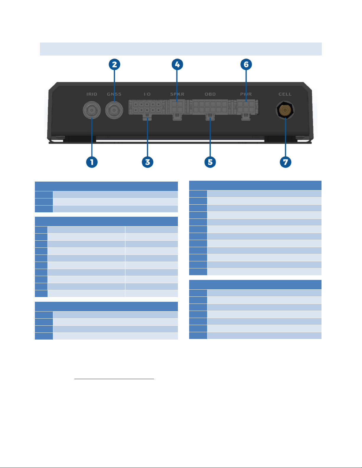
REAR PANEL DESCRIPTION
#1, 2, 7
Antennas
1
Cellular (Optional External Antenna)
2
Iridium
3
GPS (Active)
#3
Emergency Switch
& IO
1
Emergency Switch +
2
Analog IN
3
Emergency Switch IN
4
Digital IN #1 2.5VDC = Active
5
Emergency Switch LED
6
Digital IN #2 2.5VDC = Active
7
Emergency Switch Ground
8
1-Wire RFID Interface
9
RS-232 OUT
10
RS-232 IN
#4 Audio Out
1
+10-32 VDC Power
2
Speaker -
3
Speaker +
4
Ground
#5 OBD (Vehicle Interface)
1
Single Wire CAN (GMW 3089)
2
SAE J1850 Bus +
3
MS CAN High
4
Chassis Ground
5
Signal Ground
6
CAN (J-2234) High
7
ISO 9141-2 (K-Line)
8
SAE J1850 Bus -
9
MS CAN Low
10
CAN (J-2243) Low
11
ISO 9141-2 (L-Line)
12
Battery Power
#6
Power & Ignition
1
+10 – 32 VDC IN
2
Power Ground
3
10 – 32 VDC Ignition IN
4
Digital OUT #1
5
Spare
6
Digital OUT #2
NOTE: See Appendix C – Cable Diagrams for information regarding cable construction requirements.
1
6
1 1 1
4 7
3
1
6
1
3
1
7
1
4

HawkEye 5500 Installation Guide - 6/23/2020 Introduction
Page 11 of 37 © 2020 Blue Sky Network, All Right Reserved.
CONTROL PANEL DESCRIPTION
The control panel contains several LED indicators for various purposes, and several buttons to control the
device’s operations. The descriptions below reference the photo above in accordance with the numerical
value.
POWERING UNIT ON VIA FRONT PANNEL
To power the unit on via the front panel, press and hold the power button unit the power light ceases to
blink and becomes solid.
NOTE: The button for too short of a period will cause the unit to power off immediately.
SENDING A WAYPOINT
To send a waypoint, simply press the yellow waypoint button until you hear the beep. The transmit pending
light will then light up and the unit will immediately attempt to transmit a waypoint message.
ACTIVATING / DEACTIVATING EMERGENCY VIA FRONT PANNEL
1. Power / Charging Button / LED
Green = Power On & Good
Yellow = Battery < 50%
Red = Battery < 15%
Red Blink = Battery too Low to Run
Pink Blink = Unit in Bootloader Mode
Blinking = Charging
2. Signal Status LED
Green = Unit in Cellular Mode
Purple = Unit in Iridium Mode
Yellow = Poor Signal
Red = Bad Signal
Red Blink = No Network Route
3. Message Waiting LED
Green = Unread Message
4. Action Button & Transmit LED
Green = Message Pending Transmit
Blinking = Message Transmitting
5. Emergency Button / LED
Red Blink = Emergency Requested
Red Solid = Emergency Active

HawkEye 5500 Installation Guide - 6/23/2020 Introduction
Page 12 of 37 © 2020 Blue Sky Network, All Right Reserved.
To activate emergency via the front panel, press and hold the emergency button until you hear the beep.
The emergency light will illuminate and begin flashing. The light will turn solid once the emergency message
has been registered as received by SkyRouter. To deactivate emergency, press and hold the button until
you hear the beep.
NOTE: It may take up to 5 seconds of holding the emergency button to deactivate the emergency.
NOTE: Once the emergency has been activated, transmission of the initial emergency message cannot
be canceled.
BOTTOM PANEL DESCRIPTION
The bottom panel of the unit contains the following information:
Product name
Iridium IMEI
Product serial number
Required certification notifications

HawkEye 5500 Installation Guide - 6/23/2020 Mounting & Installation
Page 13 of 37 © 2020 Blue Sky Network, All Right Reserved.
MOUNTING & INSTALLATION
The HawkEye 5500 has mounting holes that allow for straps and ties to be used to secure the unit to the
vehicle. Optionally, a mounting plate can be purchased that provides easy access to attach and detach the
unit. The mounting plate provides strap guides as well as screw locations for complete secure installation.
INSTALLATION EQUIPMENT
The following equipment will be useful to have on hand during installation, but may not all be necessary to
complete installation.
Wire ties (i.e. zip ties)
Wire crimper tool
18 gauge wire of various
colors
Crimp wire splices
T-tap wire splices
Plastic trim prybar
Screwdriver & socket set
Self-taping plastic
screws
Electrical tape
Tamper indication liquid
Voltmeter
Mini fuse circuit tap
HawkEye 5500 Installation Guide - 6/23/2020 Mounting & Installation
Page 14 of 37 © 2020 Blue Sky Network, All Right Reserved.
LOCATION REQUIREMENTS
The following must be observed when mounting / installing the HE5500.
The unit should not be placed in a location where it may become a hazard to the operation of the
vehicle or in the event of a crash. (i.e. placing the unit in a location that prevents free operation of
the gear selector or steering wheel or airbags).
The unit should be securely fastened to the vehicle to ensure that accelerometer features function
properly. Failing to do so could cause stress on the wiring harness and cause accidental reports
Care should be taken to prevent the unit from moisture and excessive heat.
Care should be taken to locate the unit where the front panel buttons may not accidentally be
triggered.
Care should be taken to locate the unit where the rear connectors are not in contact with any
other object that may put stress on the connectors or the wires directly coming out of them.
Care should be taken to locate the unit where the antennas cables do not exceed their bend
radius limit.
Care should be taken to route cabling and wires through locations where they will not be
damaged by operator use of the vehicle. (i.e. routing cables through the driver footwell)
To ensure proper operation of crash and rollover feature the unit should not be mounted
vertically.
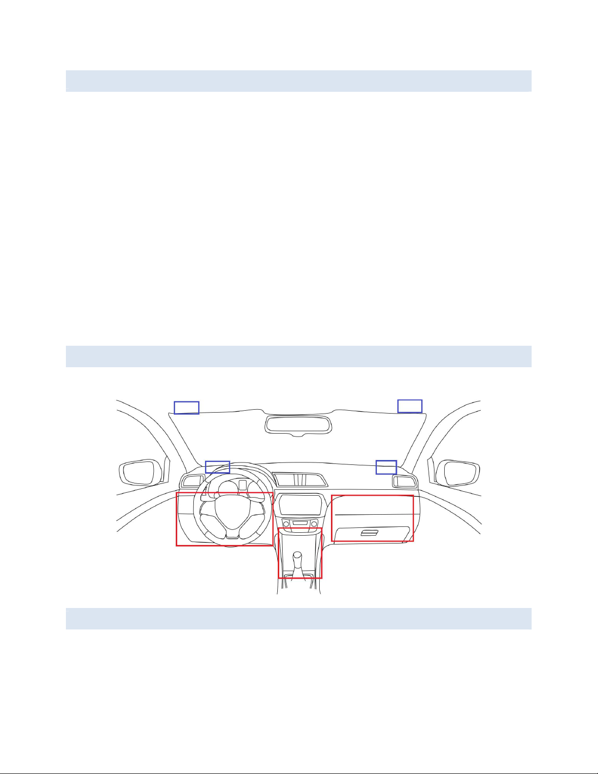
LOCATION SUGGESTIONS
Unit location suggestions are in RED. Antenna location suggestions are in BLUE.
MOUNTING
The HawkEye 5500 should be securely fastened to the vehicle in order to ensure features like crash and
rollover detection operate properly. Failure to do so may cause these features to become unstable and
unusable. There are two methods of fastening the unit to the vehicle:
HawkEye 5500 Installation Guide - 6/23/2020 Mounting & Installation
Page 15 of 37 © 2020 Blue Sky Network, All Right Reserved.
MOUNTING WITH JUST UNIT
The sides of the unit contain holes that can be used to affix the unit utilizing tie straps.
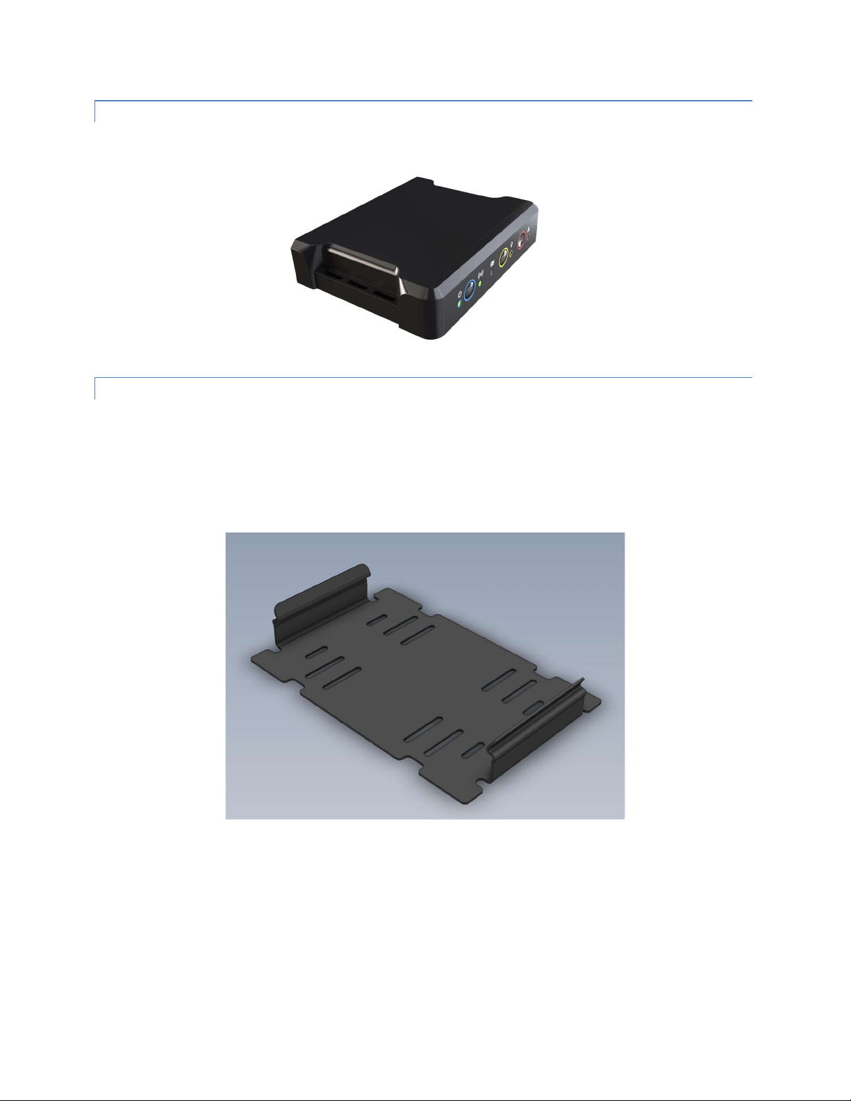
MOUNTING WITH BRACKET
The HawkEye 5500 has an optional mounting bracket that allows for the bracket to be secured to the vehicle
using screws or tie straps. The unit then clips into the bracket for easy installation and removal. The bottom
plate also provides a good surface to utilize other adhesives like Velcro.
NOTE: There is limited room between the bottom of the bracket and the bottom of the unit. Ensure that you
utilize low profile screws and thin ties before proceeding with installation.
HawkEye 5500 Installation Guide - 6/23/2020 Installation Procedure
Page 16 of 37 © 2020 Blue Sky Network, All Right Reserved.
INSTALLATION PROCEDURE
NOTE: Blue Sky Network can make cables too! If you would like, we can produce cables based on your
installation needs. Please contact us for more details.
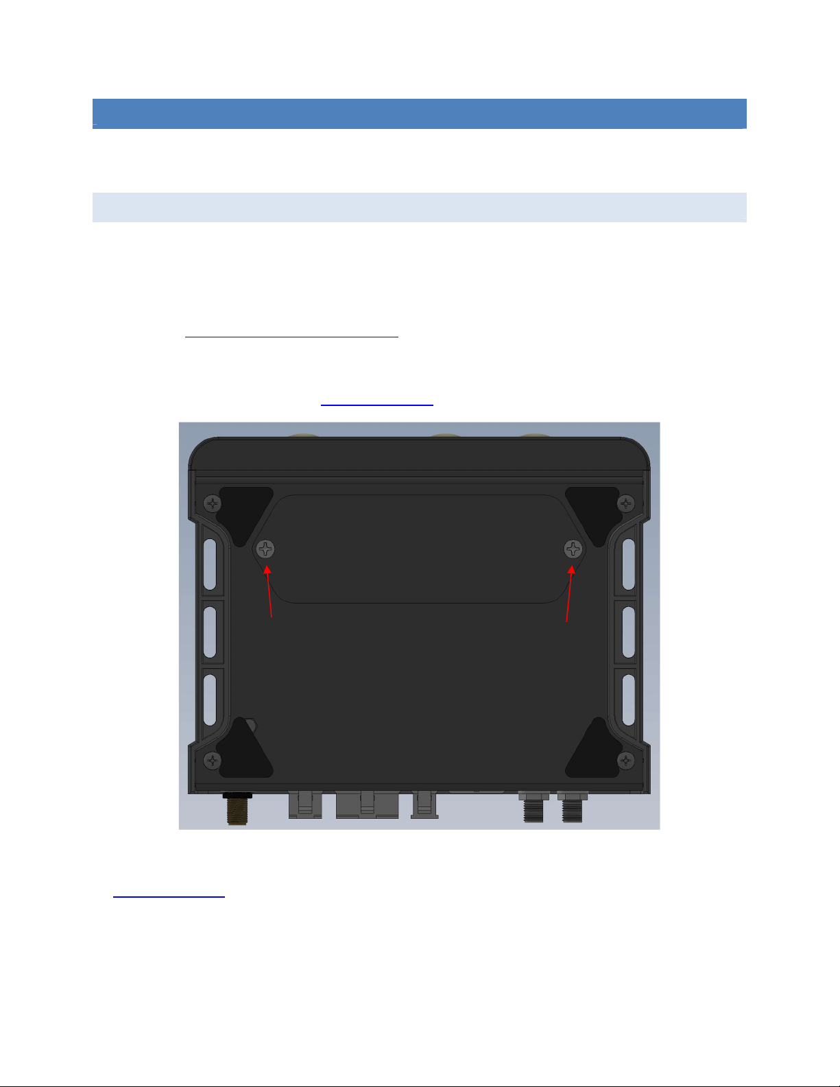
STEP 1 - INSTALL BATTERY & SIM
Due to shipping limitations on lithium powered electronics, the battery of the HE5500 may be shipped not
installed into the unit. To install the battery in the unit, remove the two screws holding the battery plate on
the bottom of the unit and insert the battery with orientation described on the battery carrier.
The unit will briefly power on to indicate proper installation of the battery. For more information about battery
operation see Replacing or Removing the Battery.
While the battery door is removed, install the SIM if necessary. Unless otherwise specified in your order,
the HE5500 will come with a global SIM already installed and configured in the unit. For information about
using your own cellular provider see Replacing the SIM.
Complete battery & SIM installation by reinstalling the screws on the bottom of the unit. If you are installing
a SIM not provided by Blue Sky Network, you may need to perform additional configuration steps described
in Replacing the SIM.

HawkEye 5500 Installation Guide - 6/23/2020 Installation Procedure
Page 17 of 37 © 2020 Blue Sky Network, All Right Reserved.
STEP 2 – ATTACH POWER
In order to avoid potential discharge of static damaging the unit, confirm that the unit is off prior to beginning
installation sequence.
NOTE: To prevent issues with power supply we suggest that these connections be soldered and not
installed using connectors. Fluctuating power supply will cause the unit to behave erratically.
PIN 1
PIN 1 should be connected to constant vehicle power as close to the battery as possible. It should also be
fused with a 3-amp inline fuse. The HawkEye 5500 can be attached behind a master battery cutoff switch
if necessary, as the internal unit will run on backup battery if required. This pin is used for running the unit
and charging the battery.
PIN 2
PIN2 should be connected to a good and safe ground point, ideally as close to the negative terminal of the
battery as possible.
PIN 3
PIN3 should be attached to ignition switched power. No current is pulled through this line as it is used for
powering off and on the unit with the vehicle. This PIN must be powered in order for the unit to remain on.
As soon as power is lost, the unit will begin its shutdown timer.
There are typically two types of switched power in a vehicle, each with their own benefits and drawbacks.
Ignition Power: Power that is only turned on when the engine is running. Use this type if you want the unit
to only report when the engine is on. This is the preferred method of powering the unit.
Accessory Power: Power that comes on when the key is turned to the accessory position, but the engine
is not necessarily started. This is what systems like the radio run off and may be easier to locate. Use this
type if you want to report or utilize the Bluetooth functionalities before the vehicle is started.
WARNING: Using this mode will prevent the ‘idle’ event from properly functioning.
A vehicle electronics installation technician can help locate the best source of switched power available.
Typically, there are two locations power can come from.
1) The ignition switch itself
2) The interior fuse panel which is usually located in the driver side footwell

HawkEye 5500 Installation Guide - 6/23/2020 Installation Procedure
Page 18 of 37 © 2020 Blue Sky Network, All Right Reserved.
STEP 3 – ATTACH ANTENNAS
The HawkEye 5500 requires the use of external GPS and Iridium antennas. In its default configuration, the
unit contains the cellular and Bluetooth antenna internally in the unit. Blue Sky Network does offer an
external cellular antenna configuration if cellular reception is not possible inside the vehicle due to armor
plating or other blocking material. Please contact us if you think you need to utilize an external cellular
antenna.
NOTE: Care must be taken to prevent damage to the antennas and cables. Do not route cables near
sources of heat and do not route cables where they may be damaged by vehicle occupants or cargo.
WARNING: Antenna cables have specific limits to how much they can be bent before experiencing
severe signal quality loss. Consult the specification sheet for your cabling to learn more about this
requirement.
TAMPER INDICATOR
For secure installation, we suggest that you apply a tamper indicator to the tightened antenna connections
to not only prevent accidental loosing but also as an indicator of tampering. Tamper indicator comes in all
forms, but we suggest a highly visible orange color like Cross Check Tamper Proof Torque Mark.
EXTERNAL ANTENNA REQUIREMENTS
Listed below are the external antenna requirements for the HawkEye 5500. Blue Sky Network can provide
antenna kits for most scenarios. Please contact us if you have any questions or need an antenna.
Iridium Antenna
Passive antenna
Frequency: 1616 – 1626.5 MHz
Impedance: 50 ohms
Polarization: RHCP
Operating temperature: -40 to +85°C
SMA male connector
Cellular Antenna
GSM (2G) Bands:
o 850,900,1800,1900 (quad band)
UMTS (3G) Bands: (3G variant)
o 800,850,900,1900,2100
LTE Cat M1/NB1 Bands: (LTE variant)
o 2, 3, 4, 5, 8, 12, 13, 20, 26, 28
SMA male connector
GNSS Antenna
Active antenna: 3V-5V
Frequency: 1575-1609MHz
Impedance: 50 ohms
Polarization: RHCP
Operating temperature: -40 to +85°C
SMA male connector
NOTE: Blue Sky Network recommends that the maximum attenuation requirements for the coax cable and
connectors that link the antenna to the HawkEye 5500 device are observed. The signal loss budget,
including the antenna cable and all connectors, from the antenna to the HE5500 unit, is < 2dB @1626MHz.
Blue Sky Network Installation Kits include a low loss coax antenna cable sized to meet this requirement.

HawkEye 5500 Installation Guide - 6/23/2020 Installation Procedure
Page 19 of 37 © 2020 Blue Sky Network, All Right Reserved.
IRIDIUM & GPS ANTENNA
The HawkEye 5500 Iridium and GPS antennas are external to the unit. Both antennas are recommended
to be positioned in a location where they have clear visibility of the sky and should not be angled at a degree
greater that 8° in reference to the horizon.
Iridium antennas have strict limits on cable loss and often require thick or specially shielded cables that
may have limits on the types of cable bends necessary for vehicle installation. If you have any questions,
regarding cable selection, bend limits or cable length limits please call us for more information.
The Iridium satellite constellation is comprised of 66 low-earth orbit (LEO) satellites that traverse the sky
every 8 to 10 minutes. At any given time, there may be from 1 to 3 satellites in view with varying locations
in the sky, at times as low as the horizon.
NOTE: Transmission from the antenna may be affected by and can affect the operation of other systems.
It is the operator’s responsibility to evaluate the location for any possible RF interference. The antennas
should be positioned at least 12 inches (0.30 meter) from any L-band antennas, particularly GPS, TCAS,
and Transponder antennas.
CELLULAR ANTENNA
The HawkEye 5500 comes in two configurations, internal wide band cellular antenna and external antenna
connection. The default configuration is with the internal wideband antenna.
If using the internal antenna, please ensure the unit is installed in a location where the it is not surrounded
by thick or heavy metal as it may affect antenna performance. If you are installing in a scenario where heavy
shielding may be employed around the unit (e.g. armored vehicle) it may be beneficial to use external
antenna.
Please contact us if you have questions regarding retrofitting units to use external antenna.
HawkEye 5500 Installation Guide - 6/23/2020 Installation Procedure
Page 20 of 37 © 2020 Blue Sky Network, All Right Reserved.
STEP 4 – OBD VEHICLE BUS INTEGRATION
The HawkEye 5500 supports tight vehicle installation using a connection to the standard On Board
Diagnostics (OBD) interface. This interface is different from passenger vehicles to commercial vehicles so
please be sure you know your installation scenario before ordering the cable.
If you find that you have purchased the wrong connector type for your installation, please contact us so we
can provide a replacement cable or direct you to an appropriate adapter cable.
PASSENGER VEHICLES
To install into passenger vehicles, locate the OBD port near the driver footwell (typically). Firmly press the
cable into the receptacle. Connect the other end of the cable into the appropriate port on the HE5500.
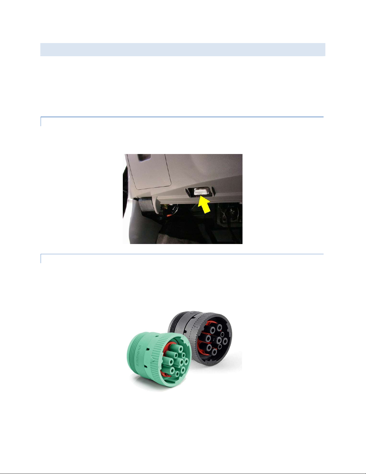
COMMERCIAL VEHICLES
To install into commercial vehicles, locate the J1939 port in the vehicle and connect the cable. Connect
the other end of the cable into the appropriate port on the HE5500. This port can be located anywhere
within the vehicle, consult your vehicle manual to find the location of the connector.
Other manuals for HawkEye 5500
1
This manual suits for next models
1
Table of contents
Other Blue Sky Network Automobile Accessories manuals


Popular Automobile Accessories manuals by other brands


ULTIMATE SPEED
ULTIMATE SPEED 279746 Assembly and Safety Advice

SSV Works
SSV Works DF-F65 manual

ULTIMATE SPEED
ULTIMATE SPEED CARBON Assembly and Safety Advice

Witter
Witter F174 Fitting instructions

WeatherTech
WeatherTech No-Drill installation instructions

TAUBENREUTHER
TAUBENREUTHER 1-336050 Installation instruction