Blue Sky Network SKYLINK 7100 User manual


Any operation. Any asset. Anywhere. SkyLink 7100 Installation Guide v1.0
Page 2of 28 © 2023 Blue Sky Network, All Rights Reserved
SkyLink 7100
Installation Guide
Version 1.0
Part Number: SL7100

SkyLink 7100 Installation Guide v1.0
Page 3of 28 © 2023 Blue Sky Network, All Rights Reserved
NOTICE
This guide is published and copyrighted by Blue Sky Network (BSN). All information and
specifications in this document are subject to change without notice. Nothing in this document is
intended to create additional or separate warranties or guarantees.
Blue Sky Network, 5353 Mission Center Rd. #222, San Diego, CA 92108
Phone: +1 858-551-3894 | Fax: +1 858-225-0794
Email: support@blueskynetwork.com | Website: www.blueskynetwork.com
© 2023 Blue Sky Network, All Rights Reserved

Any operation. Any asset. Anywhere. SkyLink 7100 Installation Guide v1.0
Page 4of 28 © 2023 Blue Sky Network, All Rights Reserved
REVISION HISTORY
Date
Ver.
By
Description
30 Aug 2021
0.0
MZ
Initial Draft
15 Oct 2021
0.1
MZ
Edited/added information based on feedback
15 Nov 2021
0.2
MZ
Revised information; updated Sensor System antenna data
23 Nov 2021
0.3
MZ
Added cable loss data for Sensor Systems
29 Nov 2021
0.4
MZ
Added min cable loss for Sensor Systems
3 Feb 2023
1.0
MZ
Updated antenna information, diagrams, & location
suggestions

SkyLink 7100 Installation Guide v1.0
Page 5of 28 © 2023 Blue Sky Network, All Rights Reserved
TABLE OF CONTENTS
Notice..................................................................................................................................... 3
Revision History.................................................................................................................... 4
Introduction .......................................................................................................................... 8
About SkyLink...............................................................................................................................................8
Installation Components ...........................................................................................................................8
Top Panel Description.................................................................................................................................9
Bottom Panel Description........................................................................................................................10
Back Panel Description.............................................................................................................................11
FAA/JAA Approval ............................................................................................................... 12
General .........................................................................................................................................................12
Installation & Operational Approval Procedures .................................................................12
Instructions for Continued Airworthiness ...............................................................................12
Environmental Qualification ...........................................................................................................12
Mounting & Installation..................................................................................................... 13
General Information .................................................................................................................................13
License Requirements .........................................................................................................................13
Cooling Air Requirements .................................................................................................................13
Aircraft Interfaces ................................................................................................................................13
PIN Assignments ....................................................................................................................................13
Power Input ..............................................................................................................................................14
Power Wiring ...........................................................................................................................................14
Ground Bonding .........................................................................................................................................14
Cable (including Antenna) & Wire Harness Routing Considerations ..........................14
Mounting.....................................................................................................................................................15

Any operation. Any asset. Anywhere. SkyLink 7100 Installation Guide v1.0
Page 6of 28 © 2023 Blue Sky Network, All Rights Reserved
Location Requirements ............................................................................................................................15
Single-Channel Iridium Antenna ............................................................................................................16
SKYLINK TERMINAL .............................................................................................................................19
Location Suggestions ................................................................................................................................19
EQUIPMENT SETUP ....................................................................................................... 20
Step 1 –Install Cellular & Iridium SIM Cards ..........................................................................20
Step 2 –Attach Cellular & Iridium Antennas.......................................................................................21
CELLULAR ANTENNA ...........................................................................................................................21
IRIDIUM ANTENNA ...............................................................................................................................21
Step 3 –Connect Power ............................................................................................................................22
Confirm Unit Status...................................................................................................................................22
Power Off Unit ............................................................................................................................................22
Step 4 –Connect Adapters.......................................................................................................................23
Step 5 –Complete Setup...........................................................................................................................23
Ground Test & Operational Flight Check Procedure ..................................................... 24
Maintenance Considerations............................................................................................ 24
Inspection ....................................................................................................................................................24
PRODUCT WARRANTY.................................................................................................. 25
Product Terms and Conditions .......................................................................................................25
Warranty Disclaimer/Limitation of Liability ...........................................................................25
Appendix A - Troubleshooting.......................................................................................... 27
Support................................................................................................................................ 28

SkyLink 7100 Installation Guide v1.0
Page 7of 28 © 2023 Blue Sky Network, All Rights Reserved
PAGE INTENTIONALLY LEFT BLANK

Any operation. Any asset. Anywhere. SkyLink 7100 Installation Guide v1.0
Page 8of 28 © 2023 Blue Sky Network, All Rights Reserved
INTRODUCTION
This installation guide demonstrates the process of installing SkyLink in an aircraft.
About SkyLink
SkyLink 7100 delivers next-generation global satellite connectivity for autonomous communications
and data monitoring beyond visual line of sight (BVLOS). Its slim design allows for easy UAV
integration and installation, enabling low latency data streaming from onboard sensors, photo
transferring, and real-time command & control. It is IP65 Certified and FCC Part 15 & 25 Certified.
SkyLink Cloud Services is a performance-driven, cloud-based analytics platform for remote, mobile,
and global operations. With SkyLink 7100 and SkyLink Cloud Services, achieve total connectivity for
all assets, in every location, across the globe.
Installation Components
Installation components are based on the desired configuration for each unit; the list below
describes some of the most common components available in the 7100 kit or purchased. All adapter
assemblies come with a length of cable that is acceptable for typical installations.
•SkyLink Dual-Mode Data Gateway
•An Iridium-approved, single channel antenna
•DC pigtail harness with Ethernet kit
•RS232 adapter
•Coaxial cable with TNC male connector on one side and SMA male on other. Allowed cable
loss for this SKU shall be 0.6dB.
NOTE: If a longer length is needed, you can purchase an extender offered in multiple lengths.
Additionally, cable diagrams can be created for specific installations upon request. Please contact us
for more information about available accessories, installation kits, and diagrams.

SkyLink 7100 Installation Guide v1.0
Page 9of 28 © 2023 Blue Sky Network, All Rights Reserved
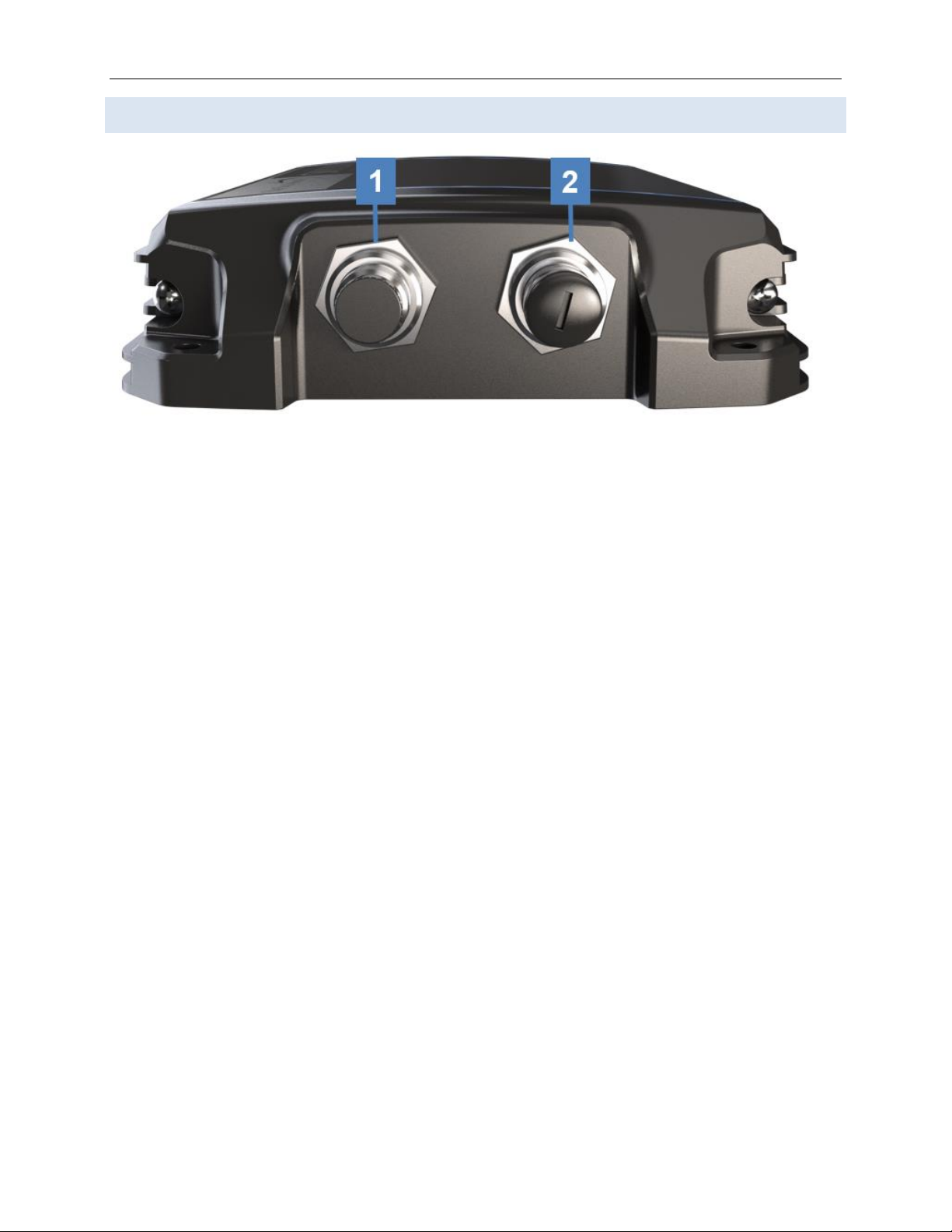
Top Panel Description
The top panel contains a power LED indicator and 2 SMA connectors for an Iridium and cellular
antenna. The descriptions below reference the photo above in accordance with the numerical value.
1. Iridium Antenna Connector
•Furthest connector from power LED indicator
•“IRI” etched into connector recess
2. Power LED Light
•Green = Initial Power On
•Red = Unit in Bootloader Mode
•Blue Blink = OS is Booting
•Blue Steady = Device is Ready
•Red Blink = Iridium Firmware Upgrade
•Blue Blink = SkyLink Firmware Upgrade
3. Cellular Antenna Connector
•Closest connector to power LED indicator
1
6
1
1
1
4
7
3
Any operation. Any asset. Anywhere. SkyLink 7100 Installation Guide v1.0
Page 10 of 28 © 2023 Blue Sky Network, All Rights Reserved
Bottom Panel Description
The bottom panel contains a power port and a connectivity port that connects to multiple adapters.
The descriptions below reference the photo above in accordance with the numerical value.
1. Power Port
•Connects to DC Power, Ethernet
•Remove connector cap before attaching the mating connector
2. Connectivity Port
•Connects to 2 wire voice (USB-POTS), and RS232
•Remove connector cap before attaching the mating connector

SkyLink 7100 Installation Guide v1.0
Page 11 of 28 © 2023 Blue Sky Network, All Rights Reserved
Back Panel Description
The back panel of the unit contains a label with the following information:
•Model series number
•Part number
•Product serial number
•Iridium IMEI
•WiFi SSID and password
•Required certification notifications
•Power and mechanical specifications
•Scannable QR code to access device WiFi
An additional label with this information can also be found in the device’s box.

Any operation. Any asset. Anywhere. SkyLink 7100 Installation Guide v1.0
Page 12 of 28 © 2023 Blue Sky Network, All Rights Reserved
FAA/JAA APPROVAL
General
Acceptance for SkyLink 7100 installation and use must be sought through the appropriate offices of
the Federal Aviation Administration (FAA), Joint Aviation Authorities (JAA), or other certifying agency.
Installation & Operational Approval Procedures
A functional ground test procedure and operational flight check procedure should be used to verify
proper installation, functional performance, and electromagnetic compatibility with existing aircraft
systems.
Instructions for Continued Airworthiness
The SkyLink 7100 components require no routine servicing or maintenance. The installation has no
additional overhaul time limitations.
Environmental Qualification
The SkyLink 7100 terminal is tested and qualified to D0160G sections 4-12, 15-21, and 25. The
Iridium-approved, single channel antenna is tested and qualified to DO160G sections 4-8, 10-14, 23,
24, and 26. It is also TSO’d to TSO C159d.
SkyLink 7100 Installation Guide v1.0
Page 13 of 28 © 2023 Blue Sky Network, All Rights Reserved
MOUNTING & INSTALLATION
General Information
Generally, aircraft modification consists of installing a dedicated single Iridium antenna with
connections for the SkyLink 7100.
NOTE: ALL aircraft antennas require professional installation.
License Requirements
The SkyLink 7100 has no licensing requirements.
Cooling Air Requirements
The SkyLink 7100 has very low power usage, so forced air cooling is not required for any of the
components. However, terminals should be kept away from heat sources.
Aircraft Interfaces
The SkyLink 7100 operates independent of aircraft navigation systems. Therefore, no aircraft
interface is required other than 10 –34 VDC power input, power return, and chassis ground.
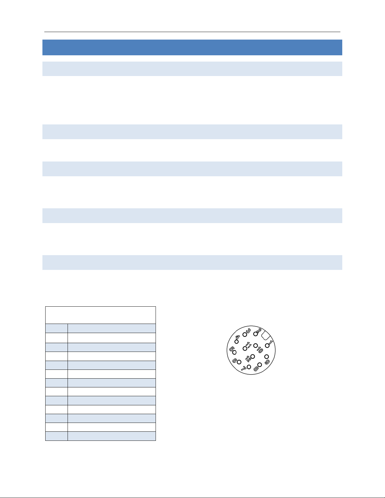
PIN Assignments
The SkyLink power port is a male M12 (P1) that accepts Amphenol M12A-12BFFA-SL7001. The
connectivity port is a female M12 (P2) that accepts Amphenol M12A-12BMMA-SL7001.
P1 (Gateway Left Side)
PIN
Description
1
ETH Green/White
2
ETH Green
3
ETH Orange/White
4
ETH Orange
5
ETH Blue/White
6
ETH Blue
7
ETH Brown/White
8
ETH Brown
9
VDC IN +
10
VDC IN –(GND)
11
SOS (Active High)
12
N/C
P1: Amphenol M12A-12PMMS-SF8001
Any operation. Any asset. Anywhere. SkyLink 7100 Installation Guide v1.0
Page 14 of 28 © 2023 Blue Sky Network, All Rights Reserved
Power Input
The only component of the SkyLink 7100 requiring aircraft power is the terminal. The SkyLink 7100
power interface supports wide voltage input in the range of 10 –34 VDC. The following input
connections are the most commonly used:
•28 VDC nominal, typically less than 0.5A
•12 VDC nominal, typically less than 1A
A single 3-amp circuit breaker is recommended to protect the aircraft power distribution system.
Power Wiring
To ensure the SkyLink 7100 will operate properly down to its rated minimum input voltage, verify
that power wires are shielded, 2 conductor, 24 AWG. It is recommended that power and ground
wires are a twisted pair to reduce signal noise.
Ground Bonding
To ensure installation characteristics match the DO-160 RF and lightning test conditions, verify that
ground wires of at least the recommended size are installed, and these wires are connected to a
bonded aircraft ground.
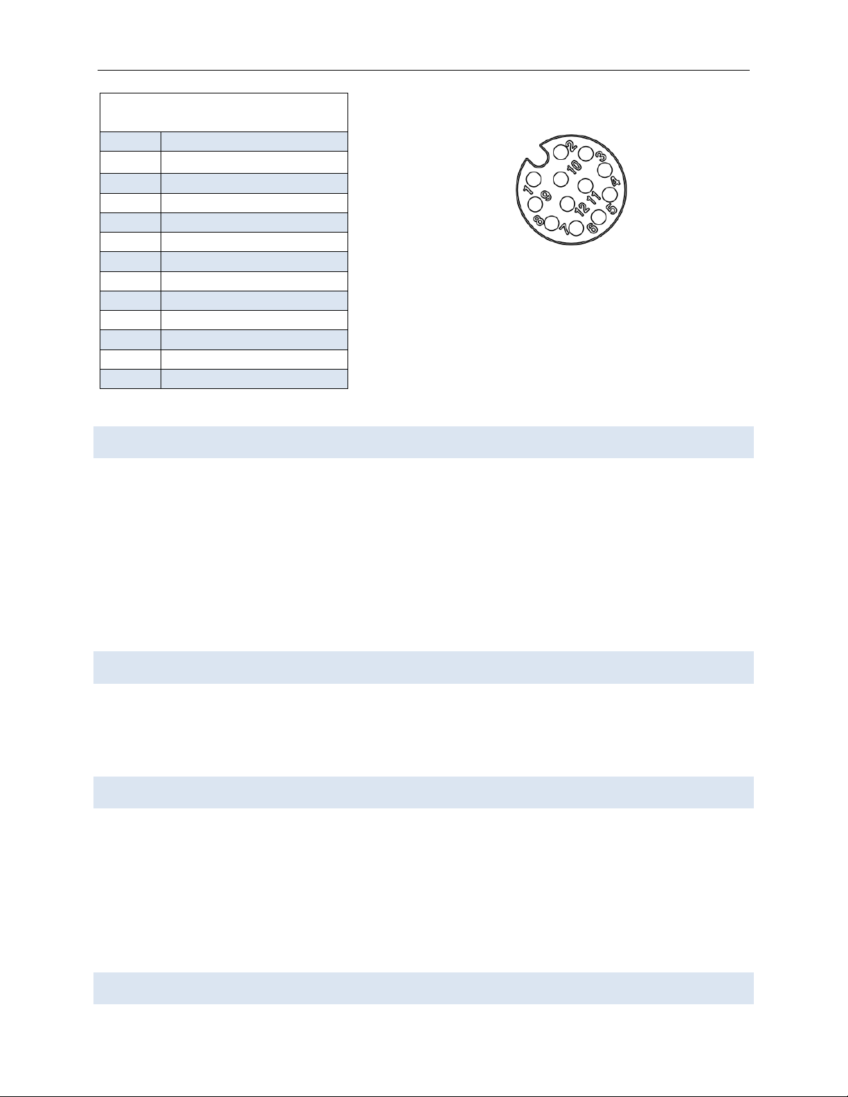
Cable (including Antenna) & Wire Harness Routing Considerations
P2 (Gateway Right Side)
PIN
Description
1
USB
2
USB
3
USB
4
USB OTG –N/C
5
USB
6
RS232 - TX
7
RS232 –RX
8
RS232 –GND
9
RS232 - CTS
10
RS232 –RTS
11
N/C
12
N/C
P2: Amphenol M12A-12PFFS-SF8001
SkyLink 7100 Installation Guide v1.0
Page 15 of 28 © 2023 Blue Sky Network, All Rights Reserved
•Cable length and routing must be carefully planned before starting the installation.
•Avoid sharp bends in the cable. Exceeding the minimum bend radius of the antenna coax cable
may result in permanent degradation of the cable loss.
•Do not locate the cable near aircraft controls.
•Observe all appropriate sections of FAR Parts 23, 25, 27, and 29 as well as AC43.13-1B and
AC43.13-2A. Damage caused by improper installation will void product warranty.
•To ensure optimal performance, the SkyLink 7100 and associated wiring should be kept a
minimum of 3 ft. from high noise sources and not routed with cables from high power sources.
•Total RF loss (including any connectors, adapters, etc.) shall be 0.6dB, which is 3m (10ft) in case
of LMR-400.
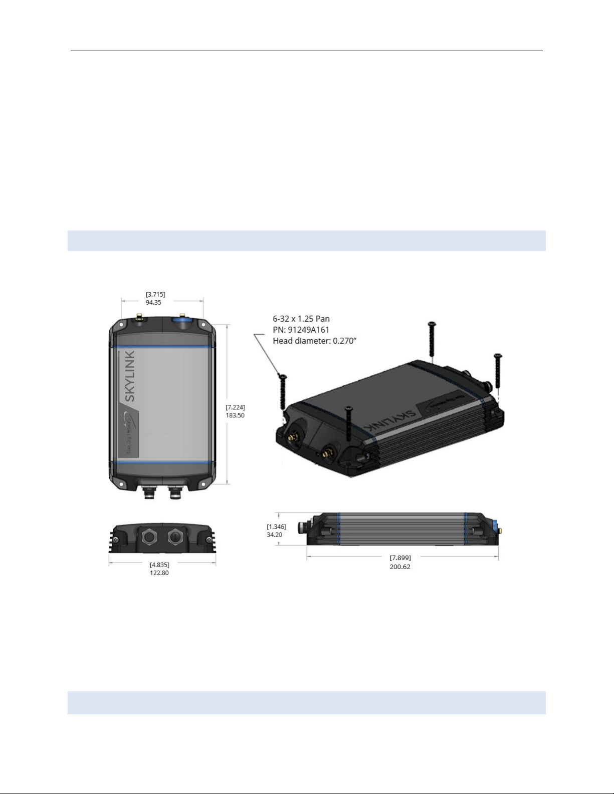
Mounting
To ensure optimal functionality, install the SkyLink device with bolts to a flat metallic surface.
Location Requirements
The following must be observed when installing the SkyLink terminal and antennas:
Any operation. Any asset. Anywhere. SkyLink 7100 Installation Guide v1.0
Page 16 of 28 © 2023 Blue Sky Network, All Rights Reserved
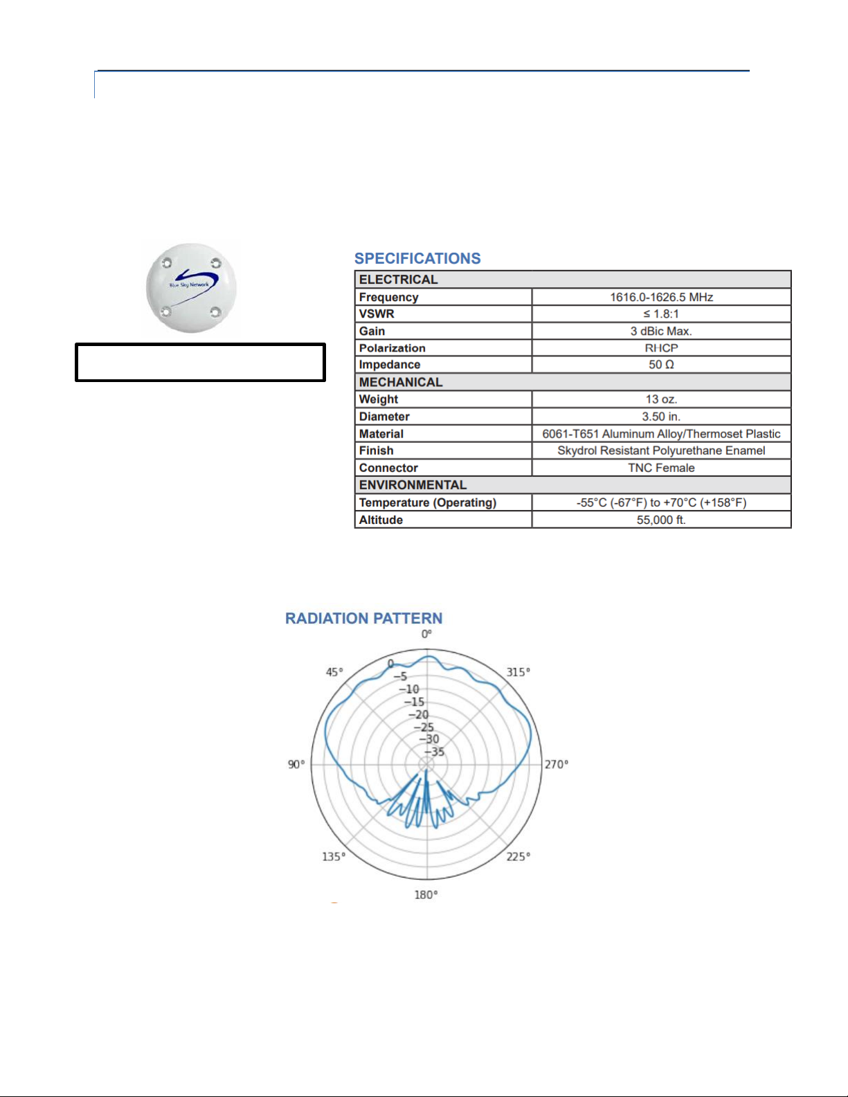
SINGLE-CHANNEL IRIDIUM ANTENNA
NOTE: A Certus-certified antenna for SkyLink is required.
Antenna installation should be completed prior to installing the SkyLink 7100. The antenna must be
installed on top of the aircraft fuselage, away from the vertical stabilizer and with an unrestricted
view of the sky down to 8 degrees above the horizon (similar to a GNSS antenna).
To prevent radiation exposure, personnel should maintain a safe distance of 30 cm. (11.8 in.)
minimum from the antenna while the unit is operating.
NOTE: Transmission from the antenna may be affected by, and can affect, the operation of
other systems; it is the operator’s responsibility to evaluate the location for any possible RF
interference. In particular, the Iridium frequency is near the allocated GNSS band. The device
Maximum cable loss: 0.6dB

SkyLink 7100 Installation Guide v1.0
Page 17 of 28 © 2023 Blue Sky Network, All Rights Reserved
should be positioned at least 39 in. (1 meter) from any L-band antennas, particularly GNSS,
TCAS, and transponder antennas.

Any operation. Any asset. Anywhere. SkyLink 7100 Installation Guide v1.0
Page 18 of 28 © 2023 Blue Sky Network, All Rights Reserved
Antenna Diagram

SkyLink 7100 Installation Guide v1.0
Page 19 of 28 © 2023 Blue Sky Network, All Rights Reserved
SKYLINK TERMINAL
On an aircraft, the terminal must be installed in a location with total RF loss (including any
connectors, adapters, etc.) of no more than 0.6dB, which is 3m (10ft) in case of LMR-400, from the
topside fuselage-mounted antenna.
Location Suggestions
For the diagram below, placement suggestions for SkyLink are in RED and for the antenna in BLUE.
There is also a brief description of each location.
SkyLink
•In the cabin, or above
headliner, within proximity
of the fuselage-mounted
antenna
Antenna
•Atop fuselage

Any operation. Any asset. Anywhere. SkyLink 7100 Installation Guide v1.0
Page 20 of 28 © 2023 Blue Sky Network, All Rights Reserved
EQUIPMENT SETUP
Step 1 –Install Cellular & Iridium SIM Cards
NOTE: If you purchased your SkyLink device through Blue Sky Network, the unit will come with
cellular and Iridium SIM cards already installed.
To install your cellular and Iridium SIM cards:
1. Carefully remove the entire bottom panel of the unit by unscrewing the Phillips screw on
each side of the panel.
2. Insert SIM cards located behind connectivity port, ensuring wires remain tucked in.
NOTE: A micro SD slot is also present behind the connectivity port. Confirm that the
SIM cards are placed into the correct holders and not the micro SD slot. If the device
does not work after installing the SIM cards, they may be in the wrong slots.
3. Re-attach bottom panel by re-screwing Phillips screws.
Table of contents
Other Blue Sky Network Automobile Accessories manuals


Popular Automobile Accessories manuals by other brands


ULTIMATE SPEED
ULTIMATE SPEED 279746 Assembly and Safety Advice

SSV Works
SSV Works DF-F65 manual

ULTIMATE SPEED
ULTIMATE SPEED CARBON Assembly and Safety Advice

Witter
Witter F174 Fitting instructions

WeatherTech
WeatherTech No-Drill installation instructions

TAUBENREUTHER
TAUBENREUTHER 1-336050 Installation instruction