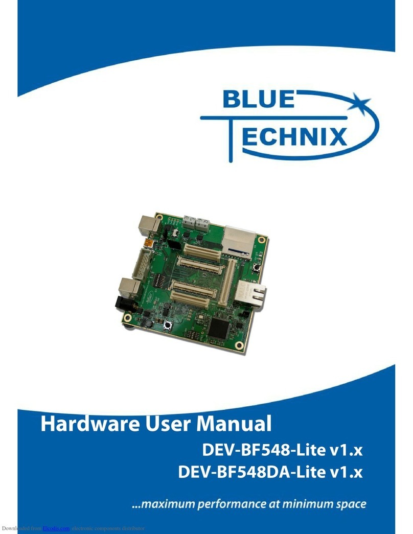
Blue Technix DEV-BF548-Lite Instructions for use

Tinyboards from Bluetechnix
www.bluetechnix.com
Hardware User Manual
DEV-BF548-Lite
DEV-BF548DA-Lite
Board V1.1

BlackfinDEV‐BF548‐Lite&DEV‐BF548DA‐LiteHardwareUserManual
Contact
Bluetechnix Mechatronische Systeme GmbH
Waidhausenstr. 3/19
A-1140 Vienna
AUSTRIA/EUROPE
http://www.bluetechnix.com
Document No.: 100-2246-1.0
Document Revision 11
2009-02-04

BlackfinDEV‐BF548‐Lite&DEV‐BF548DA‐LiteHardwareUserManual
Table of Contents
1Introduction ......................................................................................................................... 1
1.1Overview....................................................................................................................... 1
2Functional Specification...................................................................................................... 4
3PCB Placement and Mechanical Outline............................................................................. 5
3.1PCB Placement ............................................................................................................. 5
3.2Mechanical Outline....................................................................................................... 6
3.3Extension Board Footprint............................................................................................ 6
4Connector Description......................................................................................................... 8
4.1X4 –RJ45 Ethernet Connector...................................................................................... 8
4.2X9 –SD-Card Connector (bottom Mount).................................................................... 8
4.3X6 – JTAG Bypass Connector...................................................................................... 8
4.4X11 – USB-UART Connectors .................................................................................... 8
4.5X12 UART Expansion Pads ......................................................................................... 9
4.6X1, X2, X3 Expansion Connectors............................................................................... 9
4.7X8, X10 – CAN1, CAN0 Connector............................................................................ 9
4.8X5 – Power Connector.................................................................................................. 9
4.9Expansion Connectors ................................................................................................ 10
4.9.1X2 – Expansion Connector 2 ............................................................................... 10
4.9.2X1 – Expansion Connector 1 ............................................................................... 12
4.9.3X3 – Expansion Connector 3 ............................................................................... 13
5Switches, Jumper and LED Description............................................................................ 16
5.1S1 – Reset switch........................................................................................................ 16
5.2S2 – Ethernet Control Signals / SDCARD CS............................................................ 16
S3 – UART Switch ............................................................................................................... 16
5.3S4 – Boot Configuration............................................................................................. 16
5.4JP1 – Ethernet Speed Selection................................................................................... 16
5.5JP2 -– Power Supply Jumper...................................................................................... 16
5.6JP3 – RTC Power Jumper........................................................................................... 17
5.7JP4 – USB ID.............................................................................................................. 17
5.8S5 - Button.................................................................................................................. 17
5.9General Purpose LEDs................................................................................................ 17
5.10Ethernet LEDs ......................................................................................................... 17
5.11LEDs of the Debug Agent....................................................................................... 17
6Boot Mode Description ..................................................................................................... 18

BlackfinDEV‐BF548‐Lite&DEV‐BF548DA‐LiteHardwareUserManual
7Installation......................................................................................................................... 19
7.1Initial Board Setup...................................................................................................... 19
7.2Debug Agent Setup (DEV-BF548DA-Lite only)....................................................... 22
8Using the VDSP Flash Programming Tool....................................................................... 27
8.1Developing an Application......................................................................................... 27
8.2Overwriting BLACKSheep Code............................................................................... 27
9Extender Board Compatibility List.................................................................................... 28
9.1Without Extender Board............................................................................................. 28
9.2EXT-BF5xx-EXP........................................................................................................ 28
9.3EXT-BF5xx-Video ..................................................................................................... 28
9.4Audio Extender Board ................................................................................................ 29
9.5Camera Extender Board.............................................................................................. 29
9.6Analog-Digital / Digital-Analog Converter Extender Board...................................... 29
9.7USB-ETH Extender Board ......................................................................................... 29
9.8Video and Audio Extender Board............................................................................... 29
9.9Camera and Audio Extender Board............................................................................ 30
10Anomalies....................................................................................................................... 31
11Product Changes............................................................................................................. 32
12Document Revision History........................................................................................... 33
AList of Figures and Tables................................................................................................. 34

BlackfinDEV‐BF548‐Lite&DEV‐BF548DA‐LiteHardwareUserManual
Packing List
The DEV-BF548DA-Lite and the DEV-BF548-Lite Board Package contain the following
items:
1. DEV-BF548DA-Lite or DEV-BF548-Lite Board
2. 1x USB Cable (USB A/B)
3. 1x USB Cable (USB A/B) (DEV-BF548DA-Lite only)
4. 1x USB Cable (USB A/Mini USB)
5. 1x Ethernet Cable
6. 1x Power Supply.
7. Support CD
Note: The Core Modules are not shipped with the board, so you must order them separately.

BlackfinDEV‐BF548‐Lite&DEV‐BF548DA‐LiteHardwareUserManual
Edition 2007-02
© Bluetechnix Mechatronische Systeme GmbH 2007
All Rights Reserved.
The information herein is given to describe certain components and shall not be considered as
a guarantee of characteristics.
Terms of delivery and rights of technical change reserved.
We hereby disclaim any warranties, including but not limited to warranties of non-
infringement, regarding circuits, descriptions and charts stated herein.
Bluetechnix makes and you receive no warranties or conditions, express, implied, statutory or
in any communication with you. Bluetechnix specifically disclaims any implied warranty of
merchantability or fitness for a particular purpose.
Bluetechnix takes no liability for any damages and errors causing of the usage of this board.
The user of this board is responsible by himself for the functionality of his application. He is
allowed to use the board only if he has the qualification. More information is found in the
General Terms and Conditions (AGB).
Information
For further information on technology, delivery terms and conditions and prices please
contact Bluetechnix (http://www.bluetechnix.com).
Warnings
Due to technical requirements components may contain dangerous substances.
The Core Modules and development
systems contain ESD (electrostatic
discharge) sensitive devices. Electro-
static charges readily accumulate on
the human body and equipment and
can discharge without detection.
Permanent damage may occur on
devices subjected to high-energy
discharges. Proper ESD precautions
are recommended to avoid
performance degradation or loss of
functionality. Unused Core Modules
and Development Boards should be
stored in the protective shipping
package.

BlackfinDEV‐BF548‐Lite&DEV‐BF548DA‐LiteHardwareUserManual
BLACKFIN Products
Core Modules:
CM-BF533: Blackfin Processor Module powered by Analog Devices single core
ADSP-BF533 processor; up to 600MHz, 32MB RAM, 2MB Flash,
120 pin expansion connector and a size of 36.5x31.5mm
CM-BF537E: Blackfin Processor Module powered by Analog Devices single core
ADSP-BF537 processor; up to 600MHz, 32MB RAM, 4MB Flash,
integrated TP10/100 Ethernet physical transceiver, 120 pin expansion
connector and a size of 36.5x31.5mm
CM-BF537U: Blackfin Processor Module powered by Analog Devices single core
ADSP-BF537 processor; up to 600MHz, 32MB RAM, 4MB Flash,
integrated USB 2.0 Device, 120 pin expansion connector and a size
of 36.5x31.5mm (will be replaced by CM-BF527).
TCM-BF537: Blackfin Processor Module powered by Analog Devices single core
ADSP-BF537 processor; up to 500MHz, 32MB RAM, 8MB Flash,
28x28mm, 120 pin expansion connector, Ball Grid Array or Border
Pads for reflow soldering, industrial temperature range -40°C to
+85°C.
CM-BF561: Blackfin Processor Module powered by Analog Devices dual core
ADSP-BF561 processor; up to 2x 600MHz, 64MB RAM, 8MB
Flash, 120 pin expansion connector and a size of 36.5x31.5mm.
CM-BF527: The new Blackfin Processor Module is powered by Analog Devices
single core ADSP-BF527 processor; key features are USB OTG 2.0
and Ethernet. The 2x60 pin expansion connectors are backwards
compatible with other Core Modules.
CM-BF548: The new Blackfin Processor Module is powered by Analog Devices
single core ADSP-BF548 processor; key features are 64MB DDR
SD-RAM 2x100 pin expansion connectors.
Development Boards:
EVAL-BF5xx: Low cost Blackfin processor Evaluation Board with one socket for
any Bluetechnix Blackfin Core Module. Additional peripherals are
available, such as an SD-Card.
DEV-BF5xxDA-Lite: Get ready to program and debug Bluetechnix Core Modules with this
tiny development platform including a USB Based Debug Agent. The
DEV-BF5xxDA-Lite is a low cost starter development system
including VDSP++ Evaluation Software License.

BlackfinDEV‐BF548‐Lite&DEV‐BF548DA‐LiteHardwareUserManual
DEV-BF5xx-FPGA: Blackfin Development Board with two sockets for any combination
of Blackfin Core Modules. Additional peripherals are available, such
as SD-Card, Ethernet, USB host, multi-port JTAG including a USB
based Debug Agent, connector for an LCD-TFT Display and
connector for a digital camera system. A large on-board SPARTAN-3
FPGA and Soft IPs make this board the most flexible Blackfin
development platforms ever developed.
DEV-BF548DA-Lite: Get ready to program and debug Bluetechnix CM-BF548 Core
Module with this tiny development platform including a USB Based
Debug Agent. The DEV-BF548DA-Lite is a low cost starter
development system including VDSP++ Evaluation Software
License.
EXT-Boards: The following Extender Boards are available: EXT-BF5xx-Audio,
EXT-BF5xx-Video, EXT-BF5xx-Camera, EXT-BF5xx-Exp, EXT-
BF5xx-ETH-USB, EXT-BF5xx-AD/DA. Additional boards based on
customer request are also available.
Software Support:
BLACKSheep: The BLACKSheep VDK is a multithreaded framework for the
Blackfin processor family from Analog Devices that includes driver
support for a variety of hardware extensions. It is based on the real-
time VDK kernel included within the VDSP++ development
environment.
LabVIEW: LabVIEW embedded support for the CM-BF537E, CM-BF537U and
TCM-BF537 Core Modules is based upon the BLACKSheep VDK
driver Framework.
uClinux: All the Core Modules are fully supported by uClinux. The required
boot loader and uClinux can be downloaded from:
http://blackfin.uClinux.org.
Upcoming Products and Software Releases:
Keep up-to-date with all the changes to the Bluetechnix product line and software updates at:
www.bluetechnix.com
BLACKFIN Design Service
Based on more than five years of experience with Blackfin, Bluetechnix offers development
assistance as well as custom design services and software development.

Tinyboards
maximumperformanceatminimumsize
BlackfinDEV‐BF548‐Lite&DEV‐BF548DA‐LiteHardwareUserManualPage1
1 Introduction
NOTE: The DEV-BF548DA-Lite has an on-board Debug Agent, which is not available on the
DEV-BF548-Lite Board. All other features are identical! In this document, when describing
both boards, the name DEV-BF548-Lite is used.
The DEV-BF548-Lite Development Board with integrated Debug Agent is designed as a
development and application board for the high performance ADSP-BF548 based CM-BF548
Core Module. Special feature of the board is the 10/100Mbit industrial Ethernet controller.
The integrated Debug Agent is a USB based debug interface which enables programming and
debugging of the Blackfin Core Modules. It is fully compatible with the Visual DSP++
development environment. The development board provides all interfaces on dedicated
connectors or expansion connectors. Extender boards can be plugged on top of the
Development Board in order to enable additional interfaces.
1.1 Overview
The DEV-BF548-Lite Board includes the following components:
60 Pin Expansion Connector 2
USB to
UART
CM-BF548
64MB DDR SD RAM
8MB Flash
SD-Card
60 Pin Expansion Connector 1
CAN
DEBUG
AGENT USB-OTG
10/100Mbit
(Ethernet
Controller)
DC/DC
Power Supply
(5V and 3V3)
Figure 1-1: Overview of the DEV-BF548-Lite Board
DC/DC Converters
o5V@2A
o[email protected] (draws its power from the 5V output of the DC/DC)
1 Core Module Slot
oSupports the CM-BF548 Core Module
USB-to-UART Port

Tinyboards
maximumperformanceatminimumsize
BlackfinDEV‐BF548‐Lite&DEV‐BF548DA‐LiteHardwareUserManualPage2
oSupports up to 915kbps UART-USB conversion.
oEmulates a standard COM port on the computer.
oDrivers for Windows and Linux available
JTAG
oJTAG-Plug that supports all analog Devices JTAG Emulators.
Expansion Connector 1 (X1)
oData Bus
oAddress Bus
oMemory Control
oRESET
oPPI0 (Parallel Port Interface 0)
oGPIO (Programmable )
oPower Supply
Expansion Connector 2 (X2)
oPPI1 (Parallel Port Interface 1), SPORT1
oPower Supply (Main Supply Connector)
oGPIO (Programmable )
oUART0
oSPI2
Expansion Connector 3 (X3)
oATAPI Interface
oSPI0, SPI1
oSPORT2, SPORT3
oCAN 0, CAN1
oUART2, UART3
oPPI0 (Sync, D16,D17))
oSDIO Interface
oGPIO (Programmable )

Tinyboards
maximumperformanceatminimumsize
BlackfinDEV‐BF548‐Lite&DEV‐BF548DA‐LiteHardwareUserManualPage3
USB2.0 OTG Connector
oUses the On-Board USB-OTG transceiver
RJ-45 Ethernet Plug
oConnected to the On-Board SMSC LAN9218 Ethernet Controller
External Power Supply
oThe board is shipped with a 12V, 2A external DC/DC Power Supply

Tinyboards
maximumperformanceatminimumsize
BlackfinDEV‐BF548‐Lite&DEV‐BF548DA‐LiteHardwareUserManualPage4
2 Functional Specification
Figure 2-1: Functional Block Diagram
Power connector and Power supply:
The supplied power supply should be used. It can deliver up to 2A at 12V.
The input voltage range of an alternative power supply must be between 6-16V!
The on-board DC/DC power supply generates 5V and 3.3V which are made available at the
expansion connectors.
The maximum current that can be drawn from the 5V is 2A, but take care this includes the
current going into the 3.3V regulator also, because this regulator is powered by the 5V. The
maximum current that can be drawn from the 3.3V is 1.5A but note that this means at least 1A
additional load on the 5V connector.
The serial Port 0 (UART0, default Console IO) or Port1 (UART1) of the Core Module can be
routed directly to the USB Port (USB/UART Switch (S3).
An Ethernet controller (SMSC LAN9218) is connected to the data and address bus on the
baseboard providing a high speed 10/100MBit LAN Interface
An SD-Card connector is mounted on the board and is connected to the processors SD-IO
Interface. With the SD-Card one can make use of file IO Functions delivered with the
BLACKSheep Software. BLACKSheep supports SD-Cards and includes a FAT file system as
well as the most relevant File IO Functions. The complete BLACKSheep software package
can be purchased from Bluetechnix.
The USB2.0 OTG connector interfaces with the processors on-chip (ADSP-BF548) USB
Transceiver.

Tinyboards
maximumperformanceatminimumsize
BlackfinDEV‐BF548‐Lite&DEV‐BF548DA‐LiteHardwareUserManualPage5
3 PCB Placement and Mechanical Outline
3.1 PCB Placement
Figure 3-1: Connector PCB Placement
ATTENTION: Please mind the direction while inserting the Core Module!
S3
1
X8 CAN0
X5
Powe
r
1
1
80
X11
USB-UART
X7
USB JTAG X6
Ext. JTAG
01
S2
J
P
1
S4
X9
SD-CARD
X12
1 … 8
1 …4
3131
41
30
60
30
60
40
X10 CAN1
J
P
2
J
P
3
X2X1
X3
X4 Ethernet JACK
X13
USB-OTG
S5
S1
ON
Corner holes on Core Module indicating insertion Rotation
1
0
0
1
1
1
JP4

Tinyboards
maximumperformanceatminimumsize
BlackfinDEV‐BF548‐Lite&DEV‐BF548DA‐LiteHardwareUserManualPage6
3.2 Mechanical Outline
Figure 3-2: Mechanical Outline – Expansion Connector Placement
3.3 Extension Board Footprint
If you want to design your own Extension Board for the DEV-BF548, you can use the
following Board dimensions. The mating Connectors in Figure 3-3 are mounted on top.

Tinyboards
maximumperformanceatminimumsize
BlackfinDEV‐BF548‐Lite&DEV‐BF548DA‐LiteHardwareUserManualPage7
Figure 3-3: Recommended Footprint for Extension Boards – top view

Tinyboards
maximumperformanceatminimumsize
BlackfinDEV‐BF548‐Lite&DEV‐BF548DA‐LiteHardwareUserManualPage8
4 Connector Description
4.1 X4 –RJ45 Ethernet Connector
PinNo.Signal(CoreModule)IO‐Type
1TX+O
2TX‐ O
3RX+I
4NC‐
5NC‐
6RX‐ I
7NC‐
8NC‐
Table 4-1: Ethernet Connector
4.2 X9 –SD-Card Connector (bottom Mount)
PinNo.Signal(CoreModule)Description(SDCard)
0SD_D2DAT2
1SD_D3CD/DAT3
2SD_CMDCMD
3GNDVSS1
43,3VVDD
5SD_CLKCLK
6GNDVSS2
7SD_D0DAT0
8SD_D1DAT1
9‐ CD
10‐ WP
Table 4-2: SD-Card Connector
4.3 X6 – JTAG Bypass Connector
The JTAG connector is compliant with any Blackfin JTAG Emulator from Analog Devices.
When an external JTAG emulator is attached the on-board JTAG is bypassed and the external
one is automatically used.
4.4 X11 – USB-UART Connectors
Connects either UART0 (when S3 is in Pos 1) or UART1 (when S3 is in Pos 0) to the USB
Interface enabling a COM Port on the PC. UART0 is standard console IO for the
BLACKSheep Software.

Tinyboards
maximumperformanceatminimumsize
BlackfinDEV‐BF548‐Lite&DEV‐BF548DA‐LiteHardwareUserManualPage9
4.5 X12 UART Expansion Pads
When S3 is in position 1 the UART1 on PortH (TX, RX) is available on the expansion pins
and disconnected from the USB-UART Chip.
PinNo.SignalSignalType
1TxDBlackfinInputCoreModule
2RxDBlackfinOutputCoreModule
3GND
43V3RegulatedPower
Table 4-3: UART1 additional Header
4.6 X1, X2, X3 Expansion Connectors
The Expansion Connectors on the DEV-BF548-Lite for a Stacked Height of 16mm are of the
following type:
PartManufacturerManufacturerPartNr.
X1,X2AMP(StackedHeight=16mm)5‐5179010‐2
MatchingconnectorAMP5179031‐2
X3AMP(StackedHeight=16mm)5‐5179010‐3
MatchingconnectorAMP5179031‐3
Table 4-4: DEV-board connector types
The matching connector, which is used for building an extender board, can be ordered from
Bluetechnix.
4.7 X8, X10 – CAN1, CAN0 Connector
PinNo.Signal(CoreModule)IO‐Type
1CAN+I/O
2CAN‐ I/O
Table 4-5: CAN Connector
4.8 X5 – Power Connector
The board is shipped with a 12V, 2A external DC/DC Power Supply which should be used.
PinNo.SignalDescription
1Vin(+6Vto+16VDC)InputSupplyPreferable12VDC(2A)
2NC
3GND
Table 4-6: Power Supply

Tinyboards
maximumperformanceatminimumsize
BlackfinDEV‐BF548‐Lite&DEV‐BF548DA‐LiteHardwareUserManualPage10
Figure 4-1: Power connector
To connect to X141 use a “DCPP1” e.g. from Cliff Electronic Components (2.1mm * 5.5mm
* 9.5mm) plug to the power supply. Outer contact is GND, inner contact is VCC.
4.9 Expansion Connectors
The interface to the extender boards is grouped into three different connectors (X1, X2, X3).
The three tables below shows the pin out of these three connectors. The column “Pin No.
(Connector)” shows the pin number of each connector, while the column “Pin No. (Symbol)
shows the pin number of the extension connector schematic symbol, where the pins are
numbered from 1 to 200. The column “Pin No. CM” represents the pin number of the
corresponding signal on the Core Module.
4.9.1 X2 – Expansion Connector 2
PinNo.
(Symbol)
PinNo.
(Connector)
SignalSignaltypePinNoCM
11PC7I/O93
22PC6I/O94
33PC3I/O97
44PC2I/O98
55CLKOUTO70
66PE15I/O185
77PA13I/O114
88PA5I/O106
993.3VPWR
10103.3VPWR
1111PD0I/O135
1212PD2I/O137
1313PD4I/O139
1414PD6I/O141
1515PD8I/O143
1616PD10I/O145
1717PD12I/O147
1818PD14I/O149
1919PH0I/O22
2020PE12I/O188
2121PB11I/O130
2222PB9I/O128
2323PE8I/O192
2424PB13I/O132
2525PB12I/O131
2626PH1I/O23

Tinyboards
maximumperformanceatminimumsize
BlackfinDEV‐BF548‐Lite&DEV‐BF548DA‐LiteHardwareUserManualPage11
2727nARDYI21
2828PH4I/O26
29295.0V*)PWR
30305.0V2)PWR
3131Vin3)PWR
3232Vin3)PWR
3333PH7I/O29
3434nAMS3O32
3535nABE1O17
3636nABE0O16
3737PB14I/O133
3838PE7I/O193
3939PB8I/O127
4040PB10I/O129
4141PE11I/O189
4242PE13I/O187
4343PD15I/O150
4444PD13I/O148
4545PD11I/O146
4646PD9I/O144
4747PD7I/O142
4848PD5I/O140
4949PD3I/O138
5050PD1I/O136
5151GNDPWR
5252GNDPWR
5353PA1I/O102
5454PA9I/O110
5555PH3I/O25
5656PE14I/O186
5757PC1I/O99
5858PC0I/O100
5959PC5I/O95
6060PC4I/O96
4-7 Expansion Connector X2
1) Maximum current carrying capacity: 1A.
2) Pin 29 and 30 of the X8 connector are +5V stabilized from the DC/DC that can be used for
custom add-on boards or the extender boards. Maximum current carrying capacity:
900mA.(Attention: If Core Modules with USB in host mode are used, the current must be
shared with the connected USB device.
3) Pin 31 and 32 of the X7 are Vin of the external power supply minus the input protection
diode voltage. These pins can be used for custom add-on board power supplies. Maximum
current carrying capacity: 1A.

Tinyboards
maximumperformanceatminimumsize
BlackfinDEV‐BF548‐Lite&DEV‐BF548DA‐LiteHardwareUserManualPage12
4.9.2 X1 – Expansion Connector 1
PinNo.
(Symbol)
PinNo.
(Connector)
SignalSignaltypePinNoCM
611A1O1
622A3O3
633A5O5
644A7O7
655A9O9
666A11O11
677A13O13
688A15O15
699PG1I/O165
7010PG2I/O164
7111PF1I/O181
7212PF3I/O179
7313PF5I/O177
7414PF7I/O175
7515PF9I/O173
7616PF11I/O171
7717PF13I/O169
7818PF15I/O167
7919GNDPWR
8020nAMS1O30
8121nAWEO20
8222nNMII34
8323D0I/O35
8424D2I/O37
8525D4I/O39
8626D6I/O41
8727D8I/O43
8828D10I/O45
8929D12I/O47
9030D14I/O49
9131D15I/O50
9232D13I/O48
9333D11I/O46
9434D9I/O44
9535D7I/O42
9636D5I/O40
9737D3I/O38
9838D1I/O36
9939nRESETI/O67
10040nAOEO18
10141nAREO19
10242nAMS2O31
103433.3VPWR
10444PF14I/O168
10545PF12I/O170
This manual suits for next models
1
Table of contents
Other Blue Technix Computer Hardware manuals
