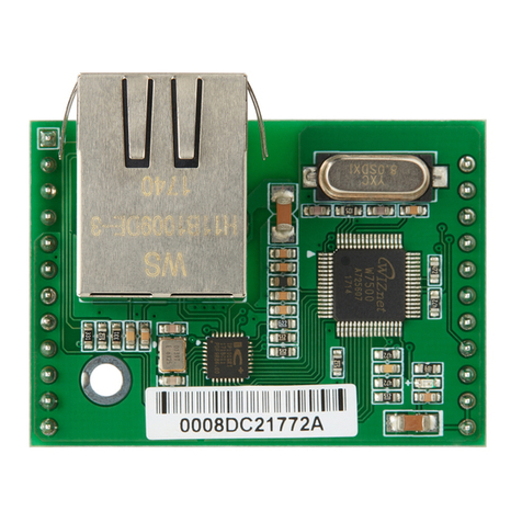
Blue Technix TIM-UP-19k-S3-Spartan 6 User manual

TIM-UP – 19k-S3-Spartan 6
V2.0.0
Software User Manual
Version 5

Contact
Bluetechnix
Waidhausenstraße 3/19
A-1140 Vienna
AUSTRIA
office@bluetechnix.com
http://www.bluetechnix.com
Date: 2014-08-19
Template No.: 900-306 / A

Table of Contents
1General Information.......................................................................................................................... 5
1.1 Symbols Used........................................................................................................................... 5
2Overview........................................................................................................................................... 6
3Interfacing......................................................................................................................................... 7
3.1 General Data Format................................................................................................................. 7
3.2 USB Interface............................................................................................................................ 8
3.3 ISM / I2C Interface..................................................................................................................... 8
3.3.1 I2C Configuration Interface ................................................................................................ 8
3.3.2 ISM Data Interface ............................................................................................................. 9
4Hardware Connector...................................................................................................................... 10
5Register Description....................................................................................................................... 13
5.1 General Registers.................................................................................................................... 13
5.2 Sequence Registers ................................................................................................................ 15
6Support........................................................................................................................................... 16
6.1 General Support...................................................................................................................... 16
6.2 Software Packages ................................................................................................................. 16
6.2.1 Related Products ............................................................................................................. 16
7Product History .............................................................................................................................. 17
7.1 Version Information ................................................................................................................. 17
7.1.1 TIMuP – 19k-S3-Spartan6-USB ........................................................................................ 17
7.1.2 TIMuP – 19k-S3-Spartan6................................................................................................. 17
7.2 Anomalies................................................................................................................................ 17
7.3 Document Revision History .................................................................................................... 17
8List of Abbreviations....................................................................................................................... 18
AList of Figures and Tables .............................................................................................................. 19
Template No.: 900-306 / A

© Bluetechnix 2014
All Rights Reserved.
The information herein is given to describe certain components and shall not be considered as a guarantee
of characteristics.
Terms of delivery and rights of technical change reserved.
We hereby disclaim any warranties, including but not limited to warranties of non-infringement, regarding
circuits, descriptions and charts stated herein.
Bluetechnix makes and you receive no warranties or conditions, express, implied, statutory or in any
communication with you. Bluetechnix specifically disclaims any implied warranty of merchantability or fitness
for a particular purpose.
Bluetechnix takes no liability for any damages and errors causing of the usage of this board. The user of this
board is responsible by himself for the functionality of his application. He is allowed to use the board only if
he has the qualification. More information is found in the General Terms and Conditions (AGB).
Information
For further information on technology, delivery terms and conditions and prices please contact Bluetechnix
(http://www.bluetechnix.com).
Warning
Due to technical requirements components may contain dangerous substances.
Template No.: 900-306 / A

Software User Manual - TIM-UP – 19k-S3-Spartan 6 Last change: 19 August 2014
Version 5
1General Information
This guide applies to the TIMuP - 19k-S3-Spartan6 module from Bluetechnix GmbH. Follow this guide chapter
by chapter to set up and understand your product. If a section of this document only applies to certain
camera parts, this is indicated at the beginning of the respective section.
1.1 Symbols Used
This guide makes use of a few symbols and conventions:
Warning
Indicates a situation which, if not avoided, could result in minor or moderate injury and/or
property damage or damage to the device.
Caution
Indicates a situation which, if not avoided, may result in minor damage to the device, in
malfunction of the device or in data loss.
Note
Notes provide information on special issues related to the device or provide information that
will make operation of the device easier.
Procedures
A procedure always starts with a headline
1. The number indicates the step number of a certain procedure you are expected to
follow. Steps are numbered sequentially.
This sign indicates an expected result of your action.
References
This symbol indicates a cross reference to a different chapter of this manual or to an
external document.
Template No.: 900-306 / A Page 5 | 19

Software User Manual - TIM-UP – 19k-S3-Spartan 6 Last change: 19 August 2014
Version 5
2Overview
The document describes the necessary steps and settings to work with the TIMuP - 19k-S3-Spartan6 module
and describes the firmware dependent interfaces.
This document applies to firmware version v2.0.0 (0x19082014)
For a hardware compatibility list please refer to our support site.
Software and documentation
https://support.bluetechnix.at/wiki/TIM-UP-19k-S3-Spartan6
Template No.: 900-306 / A Page 6 | 19

Software User Manual - TIM-UP – 19k-S3-Spartan 6 Last change: 19 August 2014
Version 5
3Interfacing
The TIMuP - 19k-S3-Spartan6 firmware provides a USB data and control interface, an ISM parallel sensor
interface and I2C control interface. All interfaces are exposed on the 100pin board to board connector.
The interfaces are split into a control and data interface. The control interface is used to set and read the
configuration of the TIMuP - 19k-S3-Spartan6 module using a set of registers. For a complete register
description refer to:
5 Register Description
3.1 General Data Format
The data output format on both, the USB and the ISM interface, is divided into four containers where each
container has its own header. The content of the four containers can be configured using the calculation
mode register.
For a complete register description refer to:
5 Register Description
Figure 3-1 Data Containers
Each header consists of 128 32bit double words of data stored in high byte first order, whereas
the data container comes in low byte first order. For a complete description of the header data
refer to our support site.
https://support.bluetechnix.at/wiki/PMDSDK_/_PMDMDK_User_Manual
#Source_Data_Container_Header
The data containers hold the pixel information configured in the calculation mode register. By default, three
data containers are configured.
-Data container 0: phase values [0..0xffff equal to a phase of 0..2π]
-Data container 1: amplitudes [0..0xffff]
-Data container 2: plausibility flags
Note
To calculate the distance you must multiply the phase value with ( c / ( 2 x f )) / 0xffff.
c…speed of light
f…modulation frequency
Template No.: 900-306 / A Page 7 | 19

Software User Manual - TIM-UP – 19k-S3-Spartan 6 Last change: 19 August 2014
Version 5
If the resulting value is greater than the ambiguity range subtract the ambiguity range. If the
value is less than 0, add the ambiguity range.
3.2 USB Interface
For interfacing the TIMuP - 19k-S3-Spartan6 module over USB, a powerful Software Development Kit is
provided. The SDK runs under Linux and Windows. Refer to our support site for downloading the SDK and
for additional information and documentation.
Software and documentation
https://support.bluetechnix.at/wiki/TIM-UP-19k-S3-Spartan6
3.3 ISM / I2C Interface
3.3.1 I2C Configuration Interface
The TIMuP - 19k-S3-Spartan6 module can be configured using an I²C connection. The I²C control interface of
the TIMuP - 19k-S3-Spartan6 module is listening on the following I2C slave address:
•I2C Address: 0x5D
•SCL Frequency: up to 400kHz
The TIMuP - 19k-S3-Spartan6 module has a set of 32bit registers and is addressed by a 16bit address
pointer. Following two figures show the timing diagrams of the I2C read and write.
Figure 3-2 I2C register read timing diagram
Figure 3-3 I2C register write timing diagram
For a complete register description refer to:
Template No.: 900-306 / A Page 8 | 19

Software User Manual - TIM-UP – 19k-S3-Spartan 6 Last change: 19 August 2014
Version 5
5 Register Description
3.3.2 ISM Data Interface
When configured to stream data over ISM in free run mode, the TIMuP - 19k-S3-Spartan6 module starts
transferring frames automatically and can only be interrupted by switching to manual trigger mode.
Each frame starts with a rising edge on the VSYNC signal followed by a rising edge of the HSYNC signal.
With the first HSYNC signal, the first data block is transmitted as shown in Figure 3-4 Timing diagram of the
ISM data interface. Every data block contains 512bytes and starts with a HSYNC.
Figure 3-4 Timing diagram of the ISM data interface
Data comes low byte first and has to be captured on every rising edge starting with the rising edge of the
HSYNC signal.
Figure 3-5 Byte order of the ISM data interface
The data stream during one frame is continuous, there is no horizontal blanking before the next
HSYNC. The vertical blanking period varies depending on frame rate. Once ISM.nDE is low, the
pixel clock never stops. ISM.PCLK stays constant at 48MHz.
Template No.: 900-306 / A Page 9 | 19

Software User Manual - TIM-UP – 19k-S3-Spartan 6 Last change: 19 August 2014
Version 5
4Hardware Connector
The following table shows the pin-out of the 100-pin TIM connector:
Pin #
Type
Signal name
Description
1
I
ISM.nDE
ISM Output enable: 0: ISM bus enabled, 1: ISM bus high Z
2
NC
3
NC
4
NC
5
NC
6
PWR
GND
Power ground
7
O
ISM.D7
ISM Data Bit 7 (MSB)
8
O
ISM.D6
ISM Data Bit 6
9
O
ISM.D5
ISM Data Bit 5
10
O
ISM.D4
ISM Data Bit 4
11
PWR
GND
Power ground
12
NC
13
O
ISM.D3
ISM Data Bit 3
14
O
ISM.D2
ISM Data Bit 2
15
O
ISM.D1
ISM Data Bit 1
16
O
ISM.D0
ISM Data Bit 0 (LSB)
17
O
ISM.STROBE
ISM Strobe signal: high during LED modulation
18
I
ISM.TRIGGER
ISM Trigger signal: trigger on rising edge
19
O
ISM.HSYNC
ISM Line Sync (HSYNC)
20
O
ISM.VSYNC
ISM Frame Sync (VSYNC)
21
O
ISM.PCLK
ISM Pixel clock
22
PWR
GND
Power ground
23
NC
24
I/O
ISM.SDA
ISM Configuration bus data signal
25
I
ISM.SCL
ISM Configuration bus clock signal
26
I
nRESET
Reset signal: hardware reset on low
27
NC
28
I
ISM.SADDR
ISM Slave address (currently not supported)
29
PWR
GND
Power ground
30
NC
31
NC
32
PWR
GND
Power ground
33
NC
34
NC
35
PWR
GND
Power ground
36
NC
37
NC
38
PWR
GND
Power ground
39
NC
40
NC
41
PWR
GND
Power ground
42
NC
43
NC
44
NC
45
NC
46
I
UART.RX
UART Receive
Template No.: 900-306 / A Page 10 | 19
Software User Manual - TIM-UP – 19k-S3-Spartan 6 Last change: 19 August 2014
Version 5
Pin #
Type
Signal name
Description
47
O
UART.TX
UART Transmit
48
NC
49
NC
50
NC
51
O
LED.SMOD
LIM Single ended mod signal
52
I/O
LED.IO
LIM one-wire communication bus (currently not supported)
53
PWR
GND
Power ground
54
O
LED.MOD_N
LIM Differential pair mod signal – negative
55
O
LED.MOD_P
LIM Differential pair mod signal – positive
56
PWR
GND
Power ground
57
O
GPIO.3
GPIO 3: status signal (toggle on every frame capture)
58
I
GPIO.2
Factory Default Reset: 4sec on low while reboot to delete
register map from flash and boot default configuration
59
I
GPIO.1
GPIO 1: not used – internal pull up
60
NC
61
NC
62
NC
63
PWR
GND
Power ground
64
NC
65
NC
66
NC
67
NC
68
PWR
GND
Power ground
69
NC
70
NC
71
PWR
GND
Power ground
72
NC
73
NC
74
I
PEN
Module power enable
75
NC
76
O
SPI.SCLK
Not used – high Z
77
I/O
SPI.SIO0
Not used – high Z
78
I/O
SPI.SIO1
Not used – high Z
79
O
SPI.nCS
Not used – high Z
80
NC
81
NC
82
NC
83
PWR
GND
Power ground
84
NC
85
NC
86
NC
87
NC
88
PWR
GND
Power ground
89
I/O
USB.D_N
USB D- Signal: high Z on reset
90
I/O
USB.D_P
USB D+ Signal: high Z on reset
91
NC
92
NC
93
O
I2CM.SCL
I2C Master Clock signal: connect I2C bus from LIM
94
O
I2CM.SDA
I2C Master Data signal: connect I2C bus from LIM
95
PWR
GND
Power ground
Template No.: 900-306 / A Page 11 | 19
Software User Manual - TIM-UP – 19k-S3-Spartan 6 Last change: 19 August 2014
Version 5
Pin #
Type
Signal name
Description
96
PWR
GND
Power ground
97
PWR
VIN
5V Power supply
98
PWR
VIN
5V Power supply
99
PWR
VIN
5V Power supply
100
PWR
VIN
5V Power supply
101
PWR
GND
Power ground
102
PWR
GND
Power ground
103
PWR
GND
Power ground
104
PWR
GND
Power ground
105
PWR
GND
Power ground
106
PWR
GND
Power ground
107
PWR
GND
Power ground
108
PWR
GND
Power ground
109
PWR
GND
Power ground
110
PWR
GND
Power ground
Table 4-1 Pin-out of the TIMuP – 19k-S3-Spartan6 connector
Template No.: 900-306 / A Page 12 | 19
Software User Manual - TIM-UP – 19k-S3-Spartan 6 Last change: 19 August 2014
Version 5
5Register Description
Note
Some critical registers are password protected. To enable the functionality, a specific value
must be written to the FlashMagic register (0x0014) prior to enabling the functionality. This
should prevent from unattended enabling of certain functions.
5.1 General Registers
Addr
(hex)
Register Name
Default
Value
(hex)
R/W
Description
01
SerialNumber1)
-
R
Bit[0:19]: Serial Number
Bit[20:31]: Device Type
02
ReleaseDate
-
R
Release date, hex value interpreted as date
03
FrameSize
1C800
R
Frame size in bytes
04
NumRows
78
R
Number of vertical pixels
05
NumColumns
A0
R
Number of horizontal pixels
0B
SequenceLength
1
R/W
Number of sequences to be calculated
0F
CalculationMode3)
22E9F7DF
R/W
Bit[21:22]: Content of container 0
0.. Intensities
1.. corr phase
2.. Amplitudes
3.. Raw phase 0
Bit[23:24]: Content of container 1
0.. Distances
1.. Distances plaus
2.. Plausibility flags
3.. Raw phase 1
Bit[25:26]: Content of container 2
0.. Amplitudes
1.. Amplitudes plaus
2.. Phase Frequency 1
3.. Raw phase 2
Bit[27:28]: Content of container 3
0.. Plausibility flags
1.. Distances
2.. Phase Frequency 2
3.. Raw phase 3
10
TempMainboard
-
R
Temperature of Mainboard in fixedpoint 9.4 [°C]
11
TempIllumination
-
R
Temperature of Illumination in fixedpoint 9.4 [°C]
16
ChipsizeColumns
A0
R
Horizontal count of pixels
17
ChipsizeRows
78
R
Vertical count of pixels
19
TriggerMode
0
R/W
Bit[0]: 0.. free run mode
1.. hardware trigger mode
2.. software trigger mode
1B
TempIlluminationGain1
0
R/W
Coefficient c3 for cubic temperature compensation of
the illumination module temperature
x/10000
1C
TempIlluminationGain2
0
R/W
Coefficient c2 for cubic temperature compensation of
the illumination module temperature
x/10000
Template No.: 900-306 / A Page 13 | 19
Software User Manual - TIM-UP – 19k-S3-Spartan 6 Last change: 19 August 2014
Version 5
Addr
(hex)
Register Name
Default
Value
(hex)
R/W
Description
1D
TempIlluminationGain3
0
R/W
Coefficient c1 for cubic temperature compensation of
the illumination module temperature
x/1000
1E
TempMainboardGain1
0
R/W
Coefficient c3 for cubic temperature compensation of
the mainboard temperature
x/10000
1F
TempMainboardGain2
0
R/W
Coefficient c2 for cubic temperature compensation of
the mainboard temperature
x/10000
20
TempMainboardGain3
0
R/W
Coefficient c1 for cubic temperature compensation of
the mainboard temperature
x/1000
21
TempLimit
46
R/W
Temperature limit for over temperature protection of the
illumination module
22
SoftwareTrigger
0
R/W
Set 1 to trigger a frame capture when in software
trigger mode (Register 0x19)
30
ModLedEnable2)
1B
R/W
Bit[0]: reserved - high
Bit[1]: enable differential LED mod signal
Bit[2]: enable single ended LED mod signal
Bit[3]: reserved - low
Bit[4]: enable ISM.STROBE signal during modulation
31
StatusLedEnable2)
0
R/W
Bit[0]: 0.. Status LED disabled
1.. Status LED enabled
37
DataInterfaceType
0
R/W
Bit[0]: 0.. USB interface
1.. ISM interface
38
FirmwareInfo
-
R
Bit[6:10]: Firmware minor version
Bit[11:15]: Firmware major version
76
ModulationFrequency0
1312D00
R/W
First possible modulation frequency [Hz]
77
ModulationFrequency1
989680
R/W
Second possible modulation frequency [Hz]
78
5MHz_Offset
0
R/W
Offset for 5MHz modulation frequency [mm]
79
7.5MHz_Offset
0
R/W
Offset for 7.5MHz modulation frequency [mm]
7A
10MHz_Offset
0
R/W
Offset for 10MHz modulation frequency [mm]
7B
15MHz_Offset
0
R/W
Offset for 15MHz modulation frequency [mm]
7C
20MHz_Offset
0
R/W
Offset for 20MHz modulation frequency [mm]
7D
25MHz_Offset
0
R/W
Offset for 25MHz modulation frequency [mm]
7E
30MHz_Offset
0
R/W
Offset for 30MHz modulation frequency [mm]
7F
FramesPerSecond
5
R/W
FPS considering the configured sequence length and
the corresponding integration times
Table 5-1 General registers description of the TIMuP – 19k-S3-Spartan6
1) The Serial Number field contains the device type code and the serial number. For a list of all device type
codes refer to:
https://support.bluetechnix.at/wiki/PMDSDK_/_PMDMDK_User_Manual#No._Serial.2FCustomer
2) For detailed information on hardware pins refer to:
4 Hardware Connector_Hardware_Connectors
3) For a detailed description of the calculation mode register refer to:
https://support.bluetechnix.at/wiki/PMDSDK_/_PMDMDK_User_Manual#Camera_Registers
Template No.: 900-306 / A Page 14 | 19
Software User Manual - TIM-UP – 19k-S3-Spartan 6 Last change: 19 August 2014
Version 5
5.2 Sequence Registers
Addr
(hex)
Register Name
Default
Value
(hex)
R/W
Description
80
Seq0PLLSelect
0
R/W
PLL config of the correct modulation frequency
Modulation frequency 0 and 1 are configured in register
76 and 77
81
Seq0IntegrationTime
1F4
R/W
Integration time of sequence 0 in µs
82
Seq0ModFreq
1312D00
R/W
Modulation frequency to use for this sequence
Only modulation frequencies set in register 76 and 77 are
valid for this register
87
Seq0AmpMin
12C
R/W
Sets the minimal amplitude for valid pixels. Pixels with an
amplitude below this value will be tagged by the
amplitude low flag
8A
Seq1PLLSelect
1
R/W
PLL config of the correct modulation frequency
Modulation frequency 0 and 1 are configured in register
76 and 77
8B
Seq1IntegrationTime
1F4
R/W
Integration time of sequence 1 in µs
8C
Seq1ModFreq
989680
R/W
Modulation frequency to use for this sequence
Only modulation frequencies set in register 76 and 77 are
valid for this register
91
Seq1AmpMin
12C
R/W
Sets the minimal amplitude for valid pixels. Pixels with an
amplitude below this value will be tagged by the
amplitude low flag
Table 5-2 Sequence registers description of the TIMuP – 19k-S3-Spartan6
Template No.: 900-306 / A Page 15 | 19
Software User Manual - TIM-UP – 19k-S3-Spartan 6 Last change: 19 August 2014
Version 5
6Support
6.1 General Support
General support for products can be found at Bluetechnix’ support site
Support Link
https://support.bluetechnix.at/wiki/TIM-UP-19k-S3-Spartan6
6.2 Software Packages
Software packages and software downloads are for registered customers only
Support Link
https://support.bluetechnix.at/wiki/TIM-UP-19k-S3-Spartan6
6.2.1 Related Products
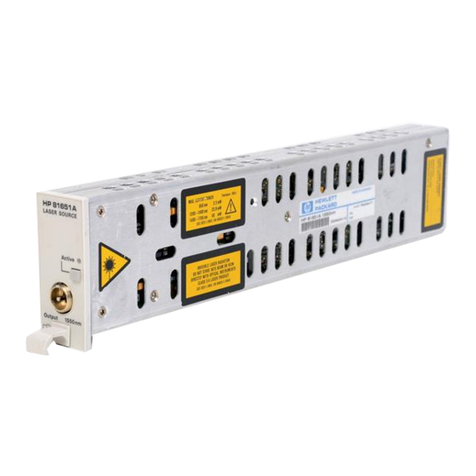
•LIM-U-LED-850
Template No.: 900-306 / A Page 16 | 19
Software User Manual - TIM-UP – 19k-S3-Spartan 6 Last change: 19 August 2014
Version 5
7Product History
7.1 Version Information
7.1.1 TIMuP – 19k-S3-Spartan6-USB
Version
Release date
Changes
0x28042014
April 2014
First preliminary version
Table 7-1: Overview TIMuP – 19k-S3-Spartan6-USB firmware changes
7.1.2 TIMuP – 19k-S3-Spartan6
Version
Release
date
Changes
2.0.0
(0x19082014)
2014 08 19
See release notes of v2.0.0
Table 7-2: Overview TIMuP – 19k-S3-Spartan6-ISM firmware changes
7.2 Anomalies
Version
Date
Description
V1.0
2014 04 28
No anomalies reported yet.
V2.0.0
2014 08 19
Compatibility to PMDSDK v0.3.0:
To get correct distance values when setting a new modulation frequency a
disconnect and reconnect has to be performed!
Table 7-3 – Product anomalies
7.3 Document Revision History
Version
Date
Document Revision
1
2014 04 28
First release V1.0 of the Document
2
2014 05 16
Unused Pins changed from pulldown to high-Z
3
2014 08 01
Description of phase values added
4
2014 08 07
USB and ISM interfaces merged, register description updated
5
2014 08 19
Added new Modulation Frequency description and finalized SUM for v2.0.0
update
Table 7-4: Revision history
Template No.: 900-306 / A Page 17 | 19

Software User Manual - TIM-UP – 19k-S3-Spartan 6 Last change: 19 August 2014
Version 5
8List of Abbreviations
Abbreviation
Description
DC
Direct Current
EBI
External Bus Interface
ESD
Electrostatic Discharge
FPN
Fixed Pattern Noise
FPPN
Fixed Phase Pattern Noise
GPIO
General Purpose Input Output
I
Input
I²C
Inter-Integrated Circuit
I/O
Input/Output
ISM
Image Sensor Module
NC
Not Connected
O
Output
OS
Operating System
PPI
Parallel Peripheral Interface
PWR
Power
ROI
Region Of Interest
SPI
Serial Peripheral Interface
SPORT
Serial Port
UART
Universal Asynchronous Receiver Transmitter
USB
Universal Serial Bus
Table 8-1: List of abbreviations
Template No.: 900-306 / A Page 18 | 19
Software User Manual - TIM-UP – 19k-S3-Spartan 6 Last change: 19 August 2014
Version 5
A List of Figures and Tables
Figures
Figure 3-1 Data Containers ................................................................................................................................. 7
Figure 3-2 I2C register read timing diagram ........................................................................................................ 8
Figure 3-3 I2C register write timing diagram ....................................................................................................... 8
Figure 3-4 Timing diagram of the ISM data interface ......................................................................................... 9
Figure 3-5 Byte order of the ISM data interface ................................................................................................. 9
Tables
Table 4-1 Pin-out of the TIMuP – 19k-S3-Spartan6 connector.......................................................................... 12
Table 5-1 General registers description of the TIMuP – 19k-S3-Spartan6 ........................................................ 14
Table 5-2 Sequence registers description of the TIMuP – 19k-S3-Spartan6 .................................................... 15
Table 7-1: Overview TIMuP – 19k-S3-Spartan6-USB firmware changes .......................................................... 17
Table 7-2: Overview TIMuP – 19k-S3-Spartan6-ISM firmware changes ........................................................... 17
Table 7-3 – Product anomalies ......................................................................................................................... 17
Table 7-4: Revision history ................................................................................................................................ 17
Table 8-1: List of abbreviations......................................................................................................................... 18
Template No.: 900-306 / A Page 19 | 19
Table of contents
Other Blue Technix Control Unit manuals

Blue Technix
Blue Technix ADEV-BF52xC V1.1 Instructions for use

Blue Technix
Blue Technix Sentis3D-M530 Instructions for use

Blue Technix
Blue Technix CM-BF537E Instructions for use

Blue Technix
Blue Technix CM-BF527 Instructions for use

Blue Technix
Blue Technix Argos3D-P320 Instructions for use

Blue Technix
Blue Technix Sentis ToF-P510 Instructions for use