Blue Wave Flow Xtreme NE4486 User manual

NE4486
Above Gound Pool Filter & Pump Manual
VER.0418

A. Safety Warnings
Read all Warnings and Cautions noted below. Failure to do so could result in serious or fatal
injury.
Prior to installation of this unit, carefully read and adhere to all CAUTION, ATTENTION, and
ADVICE notices located throughout this manual. Failure to comply with these instructions
can cause serious injury, death, or damage to the unit.
RISK OF SUCTION ENTRAPMENT HAZARD, WHICH, IF NOT AVOIDED CAN RESULT
IN SERIOUS INJURY OR DEATH. Do not block pump suction at the pump or in the pool as
this can cause severe injury or death.
Electrical wiring MUST be installed by trained professional and adhere to local code and
regulations.
Avoid electric shock. DO NOT USE power extension cords.
Connect ONLY to a Ground-Fault Circuit Interrupter (GFCI) power outlet. Consult a
qualified professional electrician for safe and proper installation of a qualified electrical
outlet.
Incorrectly installed equipment may fail, causing severe injuries or damage to the
pump-filter system.
Never submerge the filter and/or pump in water.
Never place the pump or filter in your pool.
Trapped air in the pump-filter system may cause the TANK COVER to be blown off which
can result in death, serious injury, or damage to the pump-filter system. Ensure all air is out
of system before operating.
Never change the 7 Position Multi-Port Valve while the system is operating.
ALWAYS unplug the system before changing the control valve.
Install this product with sufficient safety margin from the pool to prevent children from using
the system to access the pool.
Never PLUG or UNPLUG this unit from an electrical source while standing in water.
NEVER service this unit with electrical power cord connected.
DO NOT operate the system while the pool is being used.
KEEP CHILDREN AWAY from all electrical equipment.
NEVER ALLOW CHILDREN TO OPERATE THIS EQUIPMENT.
The Pool Owner should always exercise caution and common sense when utilizing their
swimming pool and operating equipment.
B. General Information
This manual provides information relating to the installation, utilization and maintenance of our
filtration system. We recommend that you read this manual in its entirety and keep it for future
reference.
The pump included with the filtration system is a horizontal, self-priming centrifugal pump. For
the pump to function correctly, the water temperature must not exceed 35℃/95℉. The materials
used in the pump have undergone stringent hydraulic testing and electrical inspections.
The filter tank included in the filtration system consists of high-grade polypropylene (PP). It is
manufactured as a single unit (absolutely corrosion resistant and resistant to commercially avail-
able swimming pool chemicals). (Prerequisite: Compliance with the standard recommended
Page 2

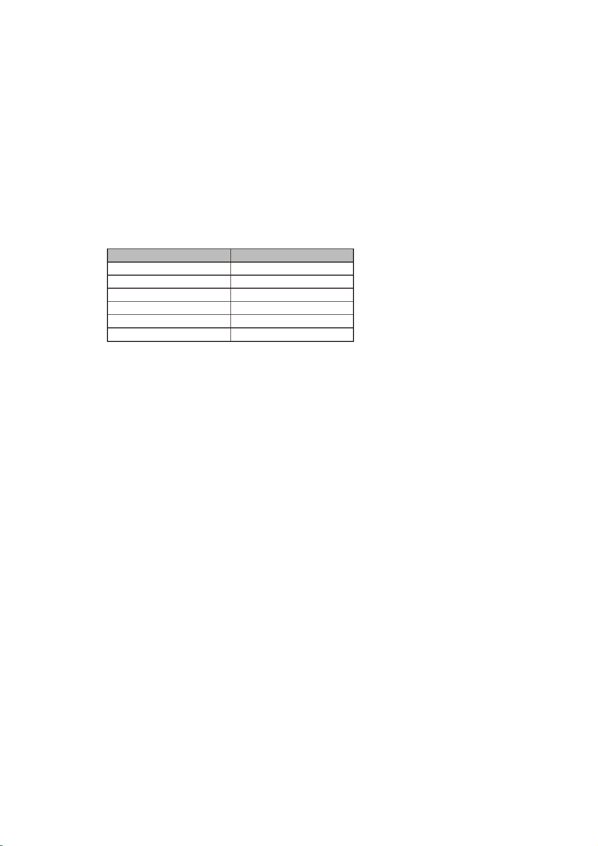
specifications for the pH- and chlorine value). It is equipped with a tank drainage system, pres-
sure gauge, built-in container components, e.g. riser pipe and under drain assembly. The filter
tank comes ready to attach and is supplied with a user-friendly 7 Position Multi-Port Valve
attached to the tank cover, an approved filter pump with hair and lint basket, and a plastic base
for ready on- site mounting.
Read this manual carefully before installation. The filtration system and pump must be installed
in accordance with all federal and local codes and standards in effect for the area of installation.
We decline all responsibility for the consequences of failure to comply with the installation
instructions. We recommend that you comply with the power source instructions to avoid over-
loading the pump motor and/or electric shock.
This filtration system is not intended for use by persons with reduced physical, sensory or mental
capabilities, or lack of experience and knowledge.
Safety notes and information boxes should always be observed.
C. Safety Notes
Your filter pump was constructed and tested and left the manufacturing plant in technically oper-
ational condition. In order to maintain this condition and ensure safe operation, the user should
observe the notes and product information contained in this technical manual. If there is any
indication that safe operation is no longer possible, the device is to be disconnected from the
power supply and secured against accidental use.
This is the case when:
The device has visible damage.
The device no longer appears functional.
After long periods of storage in poor conditions.
If the power cord or other parts of this equipment are damaged, they have to be replaced by
manufacturer or its service agent or a similarly qualified person in order to avoid danger.
D. Damage during delivery
Your filter system has been carefully and professionally packed for delivery. Please check to
ensure that the package is undamaged and that all parts are in the box. If you purchased this
product on order and the product was shipped to you, ensure that delivery is complete. Damage
to product as a result of shipping is not the responsibility of the supplier and must be immediately
reported to the shipper. The shipper assumes the liability for damages during delivery, the
supplier is not responsible for it.
E. Implied Warranty
The manufacturer warranties safe operation and reliability only under the following conditions:
The filter system is installed and operated according to the assembly and operating
instructions.
Only original replacement parts are used for repairs or replacements (consumable &
expendable parts do no fall under the warranty).
Expendable parts that do not fall under the warranty include:
All O-rings
Pressure gauge
Mechanical seal, complete
Hoses and metal hose clamps
Page 3

F. Resultant Damages
We cannot be responsible for damages to the product if the product is not used in accordance
with the instructions provided.
G. Technical Data and Specifications
The recommended filter run time is twice a day for 4 to 5 hours; regular backwashing time
is 2-3 minutes at least once a week, and floor vacuum cleaning as needed are the basic
pump requirement for maintaining clean swimming pool water!
The major components for all models are: (Confirm you have all these components before
starting installation)
The 7-way valve, filter pump, filter tank, 1 1/4’’-1 1/2’’ hose connectors and base plate.
H. Unpacking your filter system
Carefully remove the product and all component parts from the box. Cross reference all parts in
the box with the parts list reference chart to make certain all parts are present before beginning
assembly.
NOTE: Some parts may be located within the filter tank. To access these parts, you must remove
the tank cover.
Refer to *page 11 for complete EXPLODED VIEW PARTS DIAGRAMS.
I. Power source instructions
1. The Above Ground filter pump system you have purchased is equipped with a standard
electrical cord and plug which should only be connected to a power outlet protected by a 30
Amp Ground-Fault-Circuit-Interrupter (GFCI) that has been installed by a professional
electrician and adheres to local codes and regulations.
2. To avoid electric shock, power cord extensions should not be used.
3. Electrical installations for In Ground Systems should be carried out by a licensed local
electrician and follow all the applicable national and local specifications and codes for
swimming pool construction.
J. Positioning your filter system
For the operation of this filter system with Above Ground pools, you need a skimmer
installed in your pool. Either an integrated skimmer (built into the pool wall) or a suspended
skimmer (attachment to the pool wall).
The installation area must allow an adequate safety margin to the pool wall.
We recommend putting the filter system on a concrete slab or similar. Be sure the
installation is level.
Additional installation accessories such as hoses, hoses clamps, and filter sand
(not included) are available from your pool dealer.
Page 4
Flow rate
MAX Operating Pressure
Rated Voltage
Power
Amount of Sand
Pool size
NE4486Model
1850 GPH
22 psi
110V 60Hz
1/3 HP
Max. 22Ibs
Max.5000 US Gal

K. Filter-Pump Assembly (Figure 1)
1. Filter pump & Base Plate assembly
Secure filter pump to the base plate with the provided pump mounting hardware. Orient as shown.
2. The filter pump consists of the following components:
a. Pump body
b. 7 position valve
c. Internal Seal (O-Ring) seal
d. Valve plate clamping ring with bolt & nut
e. Filter Tank
f. Riser pipe and under drain assembly
g. Filter under drain assembly
h. Drain plug assembly
i. Centering plate & Sand guard
j. Base plate
k. Pressure hose or Pre-assembled PVC pipe
3. Filter Tank assembly
a. The riser pipe with conical under drain assembly is inserted into the tank (Figure 2 & 3)
b. Install the tank drain assembly as shown in figure 1, key h.
c. Make sure that the riser pipe and under drain assembly are seated on the bottom of the tank.
d. Put the centering plate sand guard on the tank opening, while centering the riser pipe.
(Figure 4)
e. Fill the filter tank to about 1/8 depth with water then up to 3/4 full with #20 Pool Filter Grade silica
sand.
NOTE: Installation of sand other than #20 Pool Filter Grade silica sand will NOT function
properly, and may void your warranty.
Cotton Tails filter media can be substituted for #20 Pool Filter Grade silica sand.
f. Attach the 7 position valve to the Tank opening using the thick O-ring and the clamping ring
(Figure 1, 5&6). Before you do this, clean tank opening to wash off any sand or accumulated
debris. The clamping ring is connected with the clamping ring bolt and nut (Figures 5 & 6).
g. The pressure gauge (if included) is screwed to the side of the 7 position valve.
Seal with Teflon tape. The pre-installed vent plug must be removed first (Figure 9).
h. Attach the pump fittings to the 7 position valve. Seal the pump fittings sufficiently with
“Teflon” tape, available at any plumbing or hardware store.
4. Pump Hose Connections (Figure 7)
a. Skimmers: Connect hose from pool skimmer to the intake fitting on the filter pump.
b. Pressure line: Connect the pre-assembled hard PVC pipe from the upper discharge point on the
top of the filter pump to the connector with designation “PUMP” on the 7-way valve.
c. Return line: Connect flexible hose from the 7-way valve port with the designation “RETURN” to
the connection for the pool location. Secure all connections with hose clamps or glue PVC pipe
connections.
d. Backwash: Connect to “WASTE” using backwash hoses and clamps. Backwash hose, clamps
are available from your local swimming pool retail professional.
Page 5

L. Filter system start up
Once the filter system has been properly assembled, the tank filled with #20 Pool Filter Grade
silica sand or Cotton Tails and the hoses connected as described, you may begin filtration. How-
ever, we recommend that you first clean and prepare the new sand. Cleaning the sand prior to
filtering your pool will remove most of the dust and tiny sand particles that may exist in the sand.
If you move straight to filtering, these particles will end up in your pool. To clean the sand, please
follow the instructions below.
Note : Do not back wash on initial installation if filter media is Cotton Tails. Follow the use instruc-
tions provided with Cotton Tails.
1. Cleaning the sand for Above Ground Pools
The swimming pool must be filled with water, according to the instructions of your pool
dealer. The water must flow towards the filter pump. Slightly open the pre-filter lid until water
flows from the pre-filter top (transparent cover with screw connection on the top of the filter
pump).
Release the shut off valve at the intake port (Skimmer) in the pool. If you plugged the intake
port (Skimmer), remove the plug to allow the water to flow into the intake hose.
With the filter-pump system installed in a level location lower than your pool’s water level
water will automatically flow into the pump-filter system. Allow the filter tank to fill with water.
Check for leaks and make any necessary adjustments to stop any leaks found.
It may be necessary to use “Teflon” tape, available at any plumbing or hardware store,
wrapped around the hose fittings threads, in order to stop leaks.
2. Start with the multi-position valve in position #5, Closed.
3. Follow the backwash process described below:
Turn off the Motor/Pump at the Power Source.
Attach backwash hose (not included) to backwash port.
Place the Multi-Port Valve in the “4 – Backwash” position.
Turn on the Pump
Run filter in BACKWASH mode until discharge water is clear.
Turn off the Motor/Pump at the Power Source.
Place the Multi-Port Valve in the “2 – RINSE” position.
Turn on the Pump.
Allow filter to run for 60 seconds to remove any remaining sand or debris residue from
pump and valve.
Turn off the Pump at the Power Source.
Place the Multi-Port Valve in the “1 – Filtration” position.
Turn on the Pump.
Your filtration system is running and ready for further operation.
Page 6

M. Filter Valve Position Operation
Page 7
Setting Complete water flow/function
Function: Regular pool filter action & vacuuming. This is the
setting the filter will be set to most of the time. In this position,
water is directed through the top of the filter where it com-
presses and flattens down the sand. Contaminations are
trapped by the sand as water makes it way to the bottom
strainer, out of the filter and back to the pool.
Filter
Position 1
Function: Use after backwashing to clean the filter bed. This
should always be done immediately after backwashing, new
sand addition or filter start-up. In this position, water is direct-
ed to the top of the tank where it flushes the valve while
sending water out the waste line.
Rinse
Position 2
Function: Circulate water after chemical treatment. This posi-
tion is used during certain pool cleanups and chemical treat-
ments when you don’t want the water contaminating the
sand. In this position, water is only directed through the valve
back to the pool and does not filter through the sand.
Circulation
Position 3
Function: Clean filter of captured debris. This is the position
needed to clean the filter & the sand. You’ll know it is time to
backwash when the pressure gauge shows more than 10
PSI above what it normally reads when the filter is clean. In
this position, water is directed through the bottom strainer,
reversing the flow through the tank. This causes the sand to
separate and lift while releasing trapped debris out the waste
port and backwash hose.
Backwash
Position 4
Function: Cleaning the hair and lint strainer. This position
stops the flow of water into the pump and filter.
CAUTION: Do not run pump with valve in this position.
Closed
Position 5
Function: Bypass the filter. This position is ideal for vacuum-
ing pools with large amounts of debris or after an algae treat-
ment. In this position, water bypassed the filter and sends all
the water and contaminates out the waste line.
Purge/Drain
Position 6
Function: Winterizing and storage. In this position, the valve
lever is between positions which removes pressure from
internal valve components for winter (off-season) storage.
CAUTION: Do not run pump with valve in this position.
Winterize
Position 7

N. Manual Vacuuming the Pool
1. For Above Ground Pools
Vacuuming is done in valve position #1, Filter, on the valve. The pool vacuum is connected by
use of a pool vacuum hose and vacuum plate directly into the skimmer. Do not turn on the
pump until the pool vacuum is connected and ready for operation.
Important: The pool vacuum hose must be fully filled with water so that the pump does not
lose prime and fill the tank with air.
P. Winterize the system in cold weather climates
1. For Above Ground Pools
Unplug the pump from the power source.
Close the shut off valves or block the flow of water at the pool inlet and return ports.
Disconnect the filtration system from the pool, drain the tank and hoses.
Place the handle on the central valve in position 7- ‘Winterize’ to relieve the tension on the
spring and internal valve components.
Store the filter system in a location protected from frost and severely cold temperatures. In
a garage or insulated storage shed is recommended.
Q. Important Do’s & Don’ts
DO’S:
Be aware and make note of the filter pressure when the sand is clean. Backwash when you
see an increase of 10 PSI on the pressure gauge.
Backwash long enough to clean the sand bed. Let the system backwash until the water
leaving the waste line is clear. Note that backwashing can remove 50 – 300 gal of water
from your pool so pay attention. Also, be aware of local codes regarding pool water dispos
al as some communities have rules or codes regarding pool water drainage.
Protect bottom strainer while replacing or adding sand. Fill the tank with 8” – 12” (about 1/8
of tank height) of water. Cover the water chamber to avoid getting sand inside the riser pipe
and under drain assembly.
Start filter in Backwash mode for about 3 minutes and then for about 1 minute in the rinse
mode before initial startup or after adding new sand. By doing this you can avoid blowing
small particles and impurities from the new sand into your pool. If some debris from new
sand does go into your pool, vacuum it with the system in purge mode, otherwise you may
send it back to the pool.
DON’TS:
Move valve handle while the pump is running. It will damage the valve and possibly other
equipment as well.
Backwash excessively. Sand filters operate more efficiently during mid-cycle. Some level of
debris in the sand bed actually helps filtration and makes the filter more effective. Too much
backwashing will reduce efficiency.
Vacuum the pool in backwash mode. You can plug up the strainer at the bottom of the filter
which will result in inefficient operation. Plus you may have to remove all of the sand to get
it unclogged.
Let filtration system run dry (without water)! If your pump runs dry too long non-warranty
damage to the pump may occur. Damage to the pump caused by dry running is NOT
covered by the warranty.
Page 8

R. Trouble Shooting
Page 9
Malfunction SolutionCause
Dirty filter bed Backwash the filter (position 4)Pressure gauge
has reading more
than 25 PSI over
the normal filtering
pressure
Clean the hair and lint strainer;
check the suction line and the water
level in pool
Hair and lint strainer
basket is dirty; Pump gets
too little water
Tighten hose clamps and connecting
fittings
Poor seal on the intake
side of pump
Replace the pumpSeal is worn out or
damaged
Check the socket and power cord/
Clean pump body
Not plugged in/
Debris blocking the
impeller
Switch on the breaker (if it is immedi-
ately tripped again, there is a defect
in pump or controls)
G.F.C.I./ or main circuit
breaker tripped
Pressure is too low
Air in the pump
Leaking filter
Replace motor or entire pumpPump motor defective
Backwash several times until the
backwash water is clear (position 4)
If the sand is newly
replaced, the undersized
grains are still present
Purge into drainpipe for 30 seconds
(position 6)
Sand in Central Valve
(from backwash)
Replace the filter bottom strainer
Loosen, but do not re-move, the air
relief valve plug on the multi-position
valve to allow any trapped air to
escape. Tighten the valve plug once
all of the air has escaped.
Filter bottom strainer or
laterals are damaged
Pump does not run
Sand in Pool
Air in system

S. Installation and Operation Illustration Figures
Page 10
1
2 3
45
7
8
9
a
a
d
d
b
i
k
e
f
c
h
g
j
6
5
3
1
2
4

Page 11
T.FlowXtreme NE4486 WITH 1/3HP PUMP PARTS BREAKDOWN
Key
1
2
3
4
5
6
7
8
9
10
11
12
13
14
Qty
1
1
1
1
1
1
1
1
1
1
1
1
1
1
1
1
2
1
1
2
2
2
2
Manf.No.
2001
2002
2003
3013
3014
3015
3016
3017
3018
2004
2005
2006
2007
3021
2009
2010
3012
3010
SPS1A250
P00175
P00176
P00177
P00178
B.W..No.
NEP4051
NEP4052
NEP4053
NEP4070
NEP4071
NEP4072
NEP4073
NEP4074
NEP4075
NEP4054
NEP4055
NEP4056
NEP4057
NEP4077
NEP4058
NEP4059
NEP4069
NEP4068
NEP4268
NEP4261
NEP4262
NEP4263
NEP4264
For Model#
NE4486
NE4486
NE4486
NE4486
NE4486
NE4486
NE4486
NE4486
NE4486
NE4486
NE4486
NE4486
NE4486
NE4486
NE4486
NE4486
NE4486
NE4486
NE4486
NE4486
NE4486
NE4486
NE4486
Part Name
7-WAY VALVE
O-RING
CAP
SCREW
NUTS & WASHER
WASHER
CLAMP PIN
RIGHT CLAMP
LEFT CLAMP
VALVE BIG O-RING
200-BLOW MOULDED TANK
SHORT PIPE
BASKET FILTER
DRAIN VALVE
BASE PLATE
SOFT HOSE
HOSE CLAMP
SAND FUNNEL
WATER PUMP
Pump Bolt Wing Nut PUMP MOUNTING HARDWARE
Pump Bolt Flat Water PUMP MOUNTING HARDWARE
Pump Bolt Lock Washer PUMP MOUNTING HARDWARE
Pump Bolt Nut PUMP MOUNTING HARDWARE
1
2
3
4
6
5
7
8
11 10
12
13
14
9
U. FX PRIME SINGLE SPEED NE4523, NEP4268, NEP4269 PUMP SERIES PARTS BREAKDOWN
Key Part Name Qty Manf. No. B.W. No. For Model#
1 Water Pump/ Motor 1 SPS1A250, 450,550
NE4523,
NEP4268-NEP4269
NE4523, NEP4268-NEP
4269
2
Transparent Hair & Lint Strainer
Cover
1
P00131
NEP4245
All
3 41 11/4"- 1 1/2" Hose Connector 2 P00132 NEP4246 All
4 42 O-ring "A"- 2 1/4" 1 P00182 NEP4265 All
5 43 O-ring "B"- 3" 1 P00183 NEP4266 All
6 44 O-ring "C"- 1.5" 1 P00184 NEP4267 All
7 45 Strainer Collar 1 P00133 NEP4247 All
8 46 Strainer Basket 1 P00134 NEP4248 All
9 47 Pump Drain Cap 1 P00135 NEP4249 All
10 48 Drain Valve O-ring 1 P00136 NEP4250 All
11 51 Motor Pump Seal 1 P00137 NEP4251 NE4523
11 51 Motor Pump Seal 1 P00138 NEP4252 NEP4268
11 51 Motor Pump Seal 1 P00138 NEP4252 NEP4269
12 52 Impeller Assembly 1 P00139 NEP4253 NE4523
12 52 Impeller Assembly 1 P00140 NEP4254 NEP4268
12 52 Impeller Assembly 1 P00140 NEP4254 NEP4269
13 53 Shaft Seal & Spring Assbly
Shaft Seal & Spring Assbly
1 P00141 NEP4255 NE4523
13 53 1 P00142 NEP4256 NEP4268
13 53 1 P00142 NEP4257 NEP4269
1
10
9
7
8
6
5
4
2
3
13
12
11
Other Blue Wave Water Filtration System manuals

Blue Wave
Blue Wave FlowXtreme Plus User manual

Blue Wave
Blue Wave FLOWXTREME COTTON TAILS NBP6058 User manual

Blue Wave
Blue Wave HYDRO NE635 User manual

Blue Wave
Blue Wave FlowXtreme Pro Series User manual

Blue Wave
Blue Wave EASY CLEAN 100 User manual

Blue Wave
Blue Wave EASY CLEAN 200 User manual

Blue Wave
Blue Wave EASY CLEAN 30 User manual
Popular Water Filtration System manuals by other brands

GENERAL ECOLOGY
GENERAL ECOLOGY Seagull IV X-1KF Installation and product use guide

HydroLogic
HydroLogic stealthro300 user manual

Cascade
Cascade 2622022 instruction manual

Aquasana
Aquasana AQ-PWFS-RB1 Setup instructions

AZZTECH
AZZTECH KMI HF-100M2UV manual

Hayward
Hayward VL Series Sand Filter Systems owner's manual