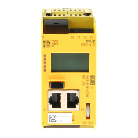
Bluebell BC780 User manual

Operations Guide
BC780, BC785T and BC785R
Control data interfaces
Ref: BC780 Operations Guide v1
BC780
SFP
S/L
ETHERNET DATA I/O
BC785T
SFP GENLOCK
S/L
ETHERNET DATA I/O
BC785R
SFP
S/L
ETHERNET DATA I/O
GENLOCK

Ref: BC780 Operations Guide v1 2
Bluebell Opticom Ltd.
Unit 2, The Quadrant
Howarth Road
Maidenhead
Berkshire
SL6 1AP
United Kingdom
Tel: +44 (0) 1628 510055
Fax: +44 (0) 1628 510057
Email: [email protected]
Web: www.bluebell.tv
Please note that all documentation herein is of a condential nature and may not be reproduced without
written conrmation from Bluebell Opticom Ltd. Any technical descriptions and schematics are to aid
service and repair only. Dissemination to a third party or parties will constitute breach of copyright.
Information in this document is subject to change without notice and does not represent a commitment
on the part of Bluebell Opticom Ltd.
Bluebell Opticom Ltd. has taken all possible steps to ensure that the information given here is both
correct and complete. In no event can Bluebell Opticom Ltd. accept any liability or responsibility for any
loss or damage to the owner of the equipment, any third party, or any equipment which may result from
use of this manual or the equipment which it describes.
Declaration of Conformities
Bluebell Opticom Ltd. hereby declares that the BC780, BC785T and BC785R Fibre Optic Transmission
Equipment is in compliance with the essential requirements and other relevant provisions of the following
EU directives: 89/336/EEC and has been assessed to EN55022B (European limits and methods of
measurement of radio disturbance characteristics); EN61000-4-2, EN61000-4-4 (Level 2), EN61000-
4-4FTB, EN61000-4-5 and EN61000-4-11 (EMC); EN61000-6-1, EN61000-6-2, EC61000-6-3 and
EC61000-6-4 (Immunity to electrical emissions).
Class 1 Laser Safety compliant: additional conformities are dependent on SFP cartridges tted.
RoSH and WEEE declaration
Bluebell Opticom Limited manages its business and collaborates with its suppliers to comply with the
European Union restriction of the use of certain hazardous substances in electrical and electronic
equipment, RoSH Directive (2002/95/EC), that came into force on 1st July 2006, and similar restrictions
in other jurisdictions.
The “crossed out wheelie bin” symbol on the product and represented above is there to remind
users of the obligation of selective collection of waste. This label is applied to various products
to indicate that the product is not to be thrown away as unsorted municipal waste. At the end of
life, dispose of this product by returning it to the point of sale or to your local municipal collection
point for recycling of electric and electronic devices.
Customer participation is important to minimize the potential effects on the environment and human
health that can result from hazardous substances that may be contained in this product.
Pleasedisposeofthisproductanditspackaginginaccordancewithlocalandnationaldisposalregulations,
including those governing the recovery and recycling of waste electrical and electronic equipment.
Contact your local waste administration, waste collection company or dealer.

Ref: BC780 Operations Guide v1 3
Table of Contents
Overview..........................................................................................................................................................4
Introduction..............................................................................................................................................4
Physical format.......................................................................................................................................5
Power requirements.............................................................................................................................5
BC780, BC785T and BC785R connections and indicators...............................................6
Signal routing ..........................................................................................................................................8
Control data I/O...................................................................................................................................10
Ethernet........................................................................................................................................10
RS-232 ..........................................................................................................................................10
RS-422 and RS-485...............................................................................................................10
GPIO...............................................................................................................................................12
Other setup options ..........................................................................................................................12
External monitoring................................................................................................................................13
Frame monitoring...............................................................................................................................13
BC100i/160i Home page or BC100/160 Frame LEDs......................................13
BC100i Card Info page.........................................................................................................13
BC160i Card Info page.........................................................................................................14
Monitoring via webpages...............................................................................................................15
Remote monitoring via SNMP....................................................................................................15
Appendix......................................................................................................................................................16
Specications – BC780, BC785T and BC785R..............................................................16
SFP Options..........................................................................................................................................16

Ref: BC780 Operations Guide v1 4
Overview
Thank you for purchasing this Bluebell Opticom professional broadcast video product. If you are
new to Bluebell products, or to the subject of transmitting video and/or other types of signal over
bre links, please take the time to read through this document before putting the card to use.
Introduction
The BC780, BC785T and BC785R plug-in cards belong to the range of the Bluebell Opticom
BC Series modular bre interfaces, designed primarily for Outside Broadcast (OB) and studio
applications. The cards have been designed for the transport of control commands or similar
data over a bre-optic link: a typical use would be to control and synchronise video cameras
installed at remote locations, as may be the case at large-scale sporting events, music festivals
and similar OB situations.
All three card types cater for control data in the following formats:
• 10/100base-T Ethernet
• RS-232
• RS-422
• RS-485
Cards will normally be used in pairs, one being installed at the control centre end (base station)
and the other at the remote end (camera station). The cards are bidirectional, so that control
response data such as command conrmations or status reports may be received by the
controlling equipment at the base station.
A general purpose input (GPI) and general purpose output (GPO) are also provided, to allow a
contact closure-generated command to be transmitted in both directions.
Card types BC785T and BC785R have the additional capability of handling a video genlock
signal as well as the control data formats listed above. The BC785T has a BNC genlock input
and the BC785R a BNC genlock output: again these two card types are intended to be used in
pairs, with the BC785T at the base station end and the BC785R adjacent to the camera.
All card types are equipped with a dual SFP carrier: this will generally be tted with a bre-optic
transceiver cartridge of the user’s choice, pre-installed by Bluebell Opticom according to the
user’s requirements (specied at time of order). An alternative option is for the carrier to be
supplied empty, so that it can be retrotted with a cartridge by the user.
Singlemode operation will normally be at 1310 nm or 1550 nm; alternative CWDM grid
wavelengths are also possible. The optical option is generally specied at the time of order. The
optical receiver will be wideband.

Ref: BC780 Operations Guide v1 5
Physical format
BC780, BC785T and BC785R cards t the Bluebell BC100i and BC160i 19” modular frames.
These frames can house fteen (BC100i) or six (BC160i) interface cards, and are tted with
dual internal AC power supplies. The cards are also compatible with earlier Bluebell 19” modular
frame types BC100 and BC160.
Alternatively, cards may be tted into smaller aluminium chassis: the BC101 and BC102 hold
one and two cards respectively and require an external DC power source, while the BC120 holds
three cards and has an integral mains PSU.
Power requirements
Power supply requirements are dictated by the enclosure type used.
BC100i modular frame:
This is normally tted with two identical AC mains PSU modules. Each module has sufcient
capacity to power a fully-loaded frame. The AC connection is via standard IEC cables, DC power
distribution inside the frame is via the motherboard. See the Operation Guide supplied with the
frame for more details.
BC160i modular frame:
This is tted as standard with dual internal AC mains power supplies, each of sufcient capacity
to power a fully-loaded frame. The AC connection is via standard IEC cables, DC power
distribution inside the frame is via the motherboard. See the Operation Guide supplied with the
frame for more details.
BC101 and BC102 single- and dual-slot chassis:
These are supplied with an external Universal AC adaptor which connects to the chassis via a
flying lead terminated in a 4-pin locking XLR connector. Mains connection is via an IEC connector.
BC120 triple-slot chassis:
This housing for three plug-in modules is tted with an internal AC mains supply; mains
connection is via a rear IEC connector.ts.

Ref: BC780 Operations Guide v1 6
BC780, BC785T and BC785R connections and indicators
BC780
SFP
S/L
ETHERNET DATA I/O
BC785T
SFP GENLOCK
S/L
ETHERNET DATA I/O
BC785R
SFP
S/L
ETHERNET DATA I/O
GENLOCK
1
222
11
33
65
3
444
1. SFP – SFP carrier for optical input and output. User’s choice of transceiver cartridge may
be tted. The lower optical connector is “receive”, that is, an input to the module, while the
upper connector is “transmit”, an output from the module.
2. S/L – bi-colour LED shows received data status. The LED illuminates green to indicate that
valid data is detected at the SFP Rx port, and red when no valid signal is detected. “Data” in
this context includes both Ethernet data and serial control commands/responses.
3. ETHERNET – Standard RJ45 Ethernet network port for transmission/reception of control
data in Ethernet format. Auto-switches between 10base-T and 100base-T data rates.
4. DATA I/O – 15-pin female Dsub connector for serial control data to RS-232, RS-422 or RS-
485 standards. Also provides GPIO connectivity. The pinout of this connector is as follows:

Ref: BC780 Operations Guide v1 7
Pin Use
1RS-232 input (Tx)
2RS-232 input GND
3RS-422/485 input (Tx) ‘-‘
4RS-422/485 input (Tx) ‘+‘
5GND
6RS-232 output (Rx) GND
7RS-232 output (Rx)
8RS-422/485 input GND
9RS-422/485 output (Tx) ‘-‘
10 RS-422/485 output (Tx) ‘+‘
11 GPI GND
12 GPI
13 GPO GND
14 GPO
15 RS-422/485 output GND
BC785T only
5. GENLOCK – BNC connector (75 ohms) for connection of standard house sync signals
such as analogue composite video, black-and-burst or tri-level sync.
BC785R only
6. GENLOCK – BNC connector (75 ohms) for retrieval of a sync signal transported over a
bre link from the BC785T.

Ref: BC780 Operations Guide v1 8
Signal routing
All card versions:
SFP
TX
SFP
RX
Dual Fibre
Mux/Demux
BC780
SFP
RX
SFP
TX
Mux/Demux
BC780
10/100base-
T Ethernet
Transceiver
Transceiver
RS-232
Transceiver
RS-
422/485
Logic
GPIO
Logic
GPIO
Transceiver
RS-
422/485
Transceiver
RS-232
10/100base-
T Ethernet
Transceiver
CAMERA LOCATION
BASE STATION
Bidirectional control
data from CCU (or
other camera control
eqipment)
Bidirectional control
data to camera
For bidirectional operation, the SFP carrier must be tted with a transceiver cartridge and
dual bres used. If no return data is required from the remote location, a single bre may be
employed, with a single channel optical transmitter cartridge in the base station BC780 and
a single channel optical receiver cartridge in the remote BC780.
The control data format in use – Ethernet, RS-232, RS-422 or RS-485 – will be determined
by the camera and associated control equipment: the BC780 is capable of transporting both
Ethernet and serial data in multiple formats, together with GPIO signals if needed, over the
bre link simultaneously. (However note that it is not possible to transmit/receive RS-422 and
RS-485 data at the same time as these formats use the same pins on the Dsub connector.)
Control data applied to the BC780 in all formats is buffered and multiplexed onto the optical
carrier. With a pair of BC780 cards, a second, symmetrical signal path is available in the
opposite direction, as the diagram above shows.

Ref: BC780 Operations Guide v1 9
BC785T and BC785R:
SFP
TX
SFP
RX
Dual Fibre
Mux/Demux
BC785T
SFP
RX
SFP
TX Mux/Demux
BC785R
10/100base-
T Ethernet
Transceiver
Transceiver
RS-232
Transceiver
RS-
422/485
Logic
GPIO
Logic
GPIO
Transceiver
RS-
422/485
Transceiver
RS-232
10/100base-
T Ethernet
Transceiver
CAMERA LOCATIONBASE STATION
Bidirectional control
data from CCU (or
other camera control
eqipment)
Bidirectional control
data to camera
ADC
Master sync
source
DAC
Sync to
camera
Genlock
output
Genlock
input
The signal processing for these cards is identical to that of the BC780, with the addition of
the ability to add an analogue video genlock signal to the multiplexed control data being sent
via the bre link. The BC785T has a genlock input and the BC785R a corresponding genlock
output. Clearly, the signal path for the genlock signal is only unidirectional: base station to
camera.
Signal routing
All card versions:
SFP
TX
SFP
RX
Dual Fibre
Mux/Demux
BC780
SFP
RX
SFP
TX
Mux/Demux
BC780
10/100base-
T Ethernet
Transceiver
Transceiver
RS-232
Transceiver
RS-
422/485
Logic
GPIO
Logic
GPIO
Transceiver
RS-
422/485
Transceiver
RS-232
10/100base-
T Ethernet
Transceiver
CAMERA LOCATION
BASE STATION
Bidirectional control
data from CCU (or
other camera control
eqipment)
Bidirectional control
data to camera
For bidirectional operation, the SFP carrier must be tted with a transceiver cartridge and
dual bres used. If no return data is required from the remote location, a single bre may be
employed, with a single channel optical transmitter cartridge in the base station BC780 and
a single channel optical receiver cartridge in the remote BC780.
The control data format in use – Ethernet, RS-232, RS-422 or RS-485 – will be determined
by the camera and associated control equipment: the BC780 is capable of transporting both
Ethernet and serial data in multiple formats, together with GPIO signals if needed, over the
bre link simultaneously. (However note that it is not possible to transmit/receive RS-422 and
RS-485 data at the same time as these formats use the same pins on the Dsub connector.)
Control data applied to the BC780 in all formats is buffered and multiplexed onto the optical
carrier. With a pair of BC780 cards, a second, symmetrical signal path is available in the
opposite direction, as the diagram above shows.

Ref: BC780 Operations Guide v1 10
Control data I/O
Ethernet
The cards are tted with a standard RJ45 ETHERNET port; the pinout is standard. It is
compatible with network data rates of 10base-T or 100base-T, automatically detecting the rate
in use and auto-switching to suit. The RJ45 socket has two integral green and yellow LEDs
indicating (green) - a valid data link has been detected, and (yellow) - port activity; this will blink
in normal operation to indicate network activity.
RS-232
All card versions can handle bidirectional serial data compliant with RS-232 standards at data
rates of up to 250 kbaud. Four pins of the 15-way Dsub connector are used:
Signal Pin
Input - data transmit (Tx) 1
Tx common 2
Output – data receive (Rx) 6
Rx common 7
Note that as other pins of the Dsub connector are used for alternative data formats, ready-made,
fully-populated cables may not operate correctly.
Most RS-232-controlled equipment will generate response messages on receiving commands,
but in many cases, the controlling equipment and the camera will operate satisfactorily if the
‘return path’ (Tx at the remote location and Rx at the base station) is ignored. Check the OEM’s
own User Guides for details.
RS-422 and RS-485
RS-422 and RS-485 serial data formats differ from RS-232 in that the transmit and receive
signals are electrically balanced. RS-485 operates at a higher voltage and provides improved
noise immunity.
All card versions can handle bidirectional serial data compliant with RS-422 or RS-485 standards
at data rates of up to 250 kbaud. Six pins of the 15-way Dsub connector are used:
Signal Pin
Input - data transmit ‘hot’ (Tx+) 4
Input - data transmit ‘cold’ (Tx-) 3
Tx common 8
Output - data receive ‘hot’ (Rx+) 10
Output - data receive ‘cold’ (Rx-) 9
Rx common 15

Ref: BC780 Operations Guide v1 11
The card will be supplied pre-congured for either RS-422 or RS-485 operation, the format
having been specied at the time of order. If this serial format option needs to be changed at any
time, the PCB jumper J5 can be moved from its factory-set position to the alternative setting.
The setting should always be the same on both cards forming the bre link.
Jumper J5: RS-422/RS-485
selection
(front panel)
RS-485 RS-422
1
2
3
1
2
3
J5 settings
Note that as other pins of the Dsub connector are used for alternative data formats, ready-made,
fully-populated cables may not operate correctly.
Most RS-422/485-controlled equipment will generate response messages on receiving
commands, but in many cases, the controlling equipment and the camera will operate
satisfactorily if the ‘return path’ (Tx at the remote location and Rx at the base station) is ignored.
Check the OEM’s own User Guides for details.

Ref: BC780 Operations Guide v1 12
GPIO
All card versions include one General Purpose Input (GPI) and one General Purpose Output
(GPO). These may be used for signalisation, or any other purpose such as transporting
additional clock or other data. The logic is non-inverting, so a ‘high’ input at the GPI will
produce a ‘high’ output at the GPO of the card at the other end of the fibre link. Four pins of
the 15-way Dsub are used:
Signal Pin
GP input (GPI) 12
GPI common 11
GP output (GPO) 14
GPO Common 13
The GPI is an isolated input and will accept DC levels or signals or up to 3.3 V amplitude. Data
rates of up to 300 MBps are supported.
The GPO uses an open-drain conguration with a maximum current sink capability of 32 mA.
Other setup options
The only user-selectable option on the PCB is jumper J5, used to select either RS-422 or
RS-485 operation via the serial port. This will be factory-set to the position specied at the time
of order.
The switches SW1 and SW2 are for factory set-up use only and should not be adjusted.

Ref: BC780 Operations Guide v1 13
External monitoring
When installed in a BC100i, BC100, BC160i or BC160 frame, all cards in the Bluebell modular
range can report their status to the frame’s monitoring system. The BC100i and BC160i frames
provide visual indication of correct card operation (or otherwise) on the Home page of the frames’
LCD touchscreens: extended card data is available on other pages. Earlier BC100 and BC160
frames provide card status information using two LEDs per card slot.
On all the above frame types, remote monitoring is also available if the optional network interface
card is tted. Contact Bluebell for the relevant .mib le.
Frame monitoring
BC100i/160i Home page or BC100/160 Frame LEDs
BC780/785T/785R
LED Ch A Green Valid optical signal detected at SFP
Red No valid optical signal detected at SFP
LED Ch B Green Data locked
Red Data not locked (invalid signal)
BC100i Card Info page
When operating correctly, the BC100i Card info page for a BC785T card will appear as below
(items specic to individual cards excepted). The Card Info pages for BC780 and BC785R are
very similar.

Ref: BC780 Operations Guide v1 14
BC160i Card Info page
When operating correctly, the BC160i Card info page for a BC785T card will display a subset of
the data shown below (items specic to individual cards excepted). Use the Up and Down scroll
buttons to show data not currently displayed. The Card Info pages for BC780 and BC785R are
very similar.

Ref: BC780 Operations Guide v1 15
Monitoring via webpages
“Overview” webpage:
BC780/785T/785R
LED Ch A
LED Ch B
Green Valid optical signal detected at SFP
Red
Green
No valid optical signal detected at SFP
Data locked
Red Data not locked (invalid signal)
“Frame Information” webpage:
Signal status BC780/785T/785R
Ch A
“good” Valid optical signal detected at SFP
“fail” No valid optical signal detected at SFP
“unknown” Card not recognised
Ch B
“good” Data locked
“fail” Data not locked (invalid signal)
“unknown” Card not recognised
Remote monitoring via SNMP
Signal status BC780/785T/785R
cardsigChA
“good” Valid optical signal detected at SFP
“fail” No valid optical signal detected at SFP
“unknown” Card not recognised
cardsigChB
“good” Data locked
“fail” Data not locked (invalid signal)
“unknown” Card not recognised

Ref: BC780 Operations Guide v1 16
Appendix
Specications – BC780, BC785T and BC785R
BC780, BC785T, BC785R
Electrical Inputs and Outputs
RS-232 Rx & Tx (unbalanced), max. 250 kbaud 15-pin Dsub connector
(shared)
RS-422/RS-485 Rx & Tx (balanced), full duplex, max. 10 Mbaud
GPIO 1 x input, 1 x output
Ethernet 10/100base-T RJ45
Genlock input (BC785T only) Analogue composite video, black & burst, tri-
level sync BNC (75 ohms)
Genlock output (BC785R only)
Optical Inputs and Outputs
Most specs determined by SFP tted. Typical values given below.
Connector 2 x female LC
Wavelength 1270 – 1610 nm
Optical power output -15 dBm @1310 nm multimode
-6 dBm @ 1310 nm singlemode
Optical receiver sensitivity >-25.5 dBm @ 1.485 Gb/s
>-26.0 dBm @ 270 Mb/s
Monitoring
Front panel S/L: bi-colour LED indicating a valid and locked
signal at optical receiver
External via BC100/BC160 frame Bi-colour LED indicating lock status of optical input
External via BC100i/BC160i frame On-screen lock status indication of optical input
External via BC100/BC100i/BC160/BC160i frame with
network card tted
Bi-colour virtual LED per channel indicating lock
status of optical input
SNMP monitoring (via BC100/BC100i/BC160/BC160i
frame with network card tted) Lock status of each optical input
Conformities
EMI/RFI Complies with 89/336/EEC, EN55032B, EN61000-4-2
Electrical Complies with EN61000-4-4FTB, EN61000-6-1, EN61000-6-2, EN61000-
6-3, EN61000-6-4
Laser Safety Complies with Class 1 laser product
RoHS & WEEE Complies with Directive 2002/95/EC
General
Input Voltage 4 – 17 V
Power consumption 5 W
Depth 75 mm (60 mm excluding connectors)
Width 20 mm (4HP)
Height 129 mm (3RU)
Weight 100 g
Operating Temperature -30 to +70 °C
SFP Options
BC780, BC785T and BC785R cards require a bre-optic transceiver cartridge to be tted in the
SFP carrier. Bluebell Opticom provides suitable SFPs upon order. Customers choosing their own
SFPs do so at their own risk.
This manual suits for next models
2
Table of contents
