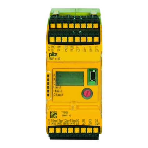
Pilz PNOZ m B1 User manual

PNOZ m B1
Operating Manual-1003790-EN-02
}Configurable, safe small controllers PNOZmulti 2

Preface
This document is the original document.
All rights to this documentation are reserved by Pilz GmbH & Co. KG. Copies may be made
for the user's internal purposes. Suggestions and comments for improving this documenta-
tion will be gratefully received.
Source code from third-party manufacturers or open source software has been used for
some components. The relevant licence information is available on the Internet on the Pilz
homepage.
Pilz®, PIT®, PMI®, PNOZ®, Primo®, PSEN®, PSS®, PVIS®, SafetyBUS p®,
SafetyEYE®, SafetyNET p®, the spirit of safety® are registered and protected trademarks
of Pilz GmbH & Co. KG in some countries.
SD means Secure Digital

Contents
Operating Manual PNOZ m B1
1003790-EN-02 | 3
1 Introduction ............................................................................................................................5
1.1 Validity of documentation.......................................................................................................... 5
1.2 Using the documentation .......................................................................................................... 5
1.3 Definition of symbols................................................................................................................. 5
2 Overview .................................................................................................................................7
2.1 Range ....................................................................................................................................... 7
2.2 Unit features ............................................................................................................................. 7
2.3 USB memory ............................................................................................................................ 7
2.4 Front view ................................................................................................................................. 8
3 Safety ...................................................................................................................................... 9
3.1 Intended use ............................................................................................................................. 9
3.2 System requirements................................................................................................................ 10
3.3 Safety regulations ..................................................................................................................... 10
3.3.1 Safety assessment ................................................................................................................... 10
3.3.2 Use of qualified personnel ........................................................................................................ 10
3.3.3 Warranty and liability ................................................................................................................ 10
3.3.4 Disposal .................................................................................................................................... 10
3.3.5 For your safety.......................................................................................................................... 11
4 Function description ............................................................................................................. 12
4.1 Integrated protection mechanisms............................................................................................ 12
4.2 Functions .................................................................................................................................. 12
4.3 System reaction time ................................................................................................................ 12
4.4 Detection of shorts across contacts.......................................................................................... 13
4.5 Block diagram ........................................................................................................................... 14
4.6 Diagnostics ............................................................................................................................... 14
4.7 Ethernet interface ..................................................................................................................... 14
5 Installation ..............................................................................................................................15
5.1 Control cabinet installation........................................................................................................ 15
5.1.1 Mounting distances................................................................................................................... 15
5.2 Dimensions in mm .................................................................................................................... 17
5.3 Connecting the base unit and expansion modules ................................................................... 17
6 Commissioning ......................................................................................................................19
6.1 General wiring guidelines ......................................................................................................... 19
6.2 Connection................................................................................................................................ 19
6.3 Ethernet interfaces.................................................................................................................... 20
6.3.1 RJ45 interfaces ("Ethernet") ..................................................................................................... 20
6.3.2 Requirements of the connection cable and connector.............................................................. 20
6.3.3 Interface configuration .............................................................................................................. 20
6.3.4 RJ45 connection cable ............................................................................................................. 21
6.4 Use USB memory ..................................................................................................................... 22
6.5 Load project from PNOZmulti Configurator .............................................................................. 22
6.6 Activate project via the display on the base unit....................................................................... 23
6.7 Display settings......................................................................................................................... 23

Contents
Operating Manual PNOZ m B1
1003790-EN-02 | 4
6.7.1 Operate menu........................................................................................................................... 23

6.7.2 Displays and settings................................................................................................................ 24
6.7.2.1 Status indicators ....................................................................................................................... 25
6.7.2.2 Project menu............................................................................................................................. 26
6.7.2.3 Device Info menu...................................................................................................................... 28
6.7.2.4 Error Stack menu...................................................................................................................... 29
6.7.2.5 Operating Info menu ................................................................................................................. 29
6.7.2.6 Connections menu.................................................................................................................... 30
6.7.2.7 Ethernet menu .......................................................................................................................... 30
6.7.2.8 Time menu................................................................................................................................ 32
6.7.2.9 System mode menu.................................................................................................................. 32
6.8 Function test during commissioning ......................................................................................... 32
7 Operation ................................................................................................................................33
7.1 LED indicators .......................................................................................................................... 33
7.2 Show error stack on the display................................................................................................ 34
8 Technical details ....................................................................................................................35
8.1 Safety characteristic data ......................................................................................................... 37
9 Order reference ......................................................................................................................38
9.1 Product ..................................................................................................................................... 38
9.2 Accessories .............................................................................................................................. 38

Introduction
Operating Manual PNOZ m B1
1003790-EN-02 | 5
1 Introduction
1.1 Validity of documentation
This documentation is valid for the product PNOZ m B1 from Version HW:01, FW:01.05.
This operating manual explains the function and operation, describes the installation and
provides guidelines on how to connect the product.
1.2 Using the documentation
This document is intended for instruction. Only install and commission the product if you
have read and understood this document. The document should be retained for future ref-
erence.
1.3 Definition of symbols
Information that is particularly important is identified as follows:
DANGER!
This warning must be heeded! It warns of a hazardous situation that poses
an immediate threat of serious injury and death and indicates preventive
measures that can be taken.
WARNING!
This warning must be heeded! It warns of a hazardous situation that could
lead to serious injury and death and indicates preventive measures that can
be taken.
CAUTION!
This refers to a hazard that can lead to a less serious or minor injury plus
material damage, and also provides information on preventive measures
that can be taken.
NOTICE
This describes a situation in which the product or devices could be dam-
aged and also provides information on preventive measures that can be
taken. It also highlights areas within the text that are of particular import-
ance.

Introduction
Operating Manual PNOZ m B1
1003790-EN-02 | 6
INFORMATION
This gives advice on applications and provides information on special fea-
tures.

Overview
Operating Manual PNOZ m B1
1003790-EN-02 | 7
2 Overview
2.1 Range
}Base unit PNOZ m B1
}Terminator
}Documentation on data medium
}USB memory
2.2 Unit features
Application of the product PNOZ m B1:
Base unit of the configurable control system PNOZmulti 2
The product has the following features:
}Can be configured in the PNOZmulti Configurator
}Support for module programs
}4 test pulse outputs to detect shorts between the inputs
}Backlit display for:
– Status information
– Device information
– Diagnostics
– Activate project
– Ethernet settings
– System's date and time
– Stop and start device
}Multifunction switch for menu control
}Ethernet interface with switch
}LED indicator for:
– Operating status
– Error messages
– Diagnostics
– Supply voltage
}Plug-in connection terminals:
Either spring-loaded terminal or screw terminal available as an accessory (see Order ref-
erences for accessories).
}Expansion modules can be connected
(please refer to the document "PNOZmulti System Expansion" for details of the type and
number that can be connected)
2.3 USB memory
To save and transfer projects you need the Pilz USB memory that is supplied with the
device (plugged into the device).

Overview
Operating Manual PNOZ m B1
1003790-EN-02 | 8
2.4 Front view
LED 1
LED 2
LED 3
LED 4
LED 5
Hardware version (HW)
Serial number
Material number
LED 1
LED 2
LED 3
LED 4
LED 5
LED 1
LED 2
LED 3
LED 4
LED 5
Firmware version (FW)
Legend
X1/X2: Ethernet interface
X3: Test pulse outputs T0 - T3
X4: Labelling clip for firmware version
LED 1: Supply voltage
LED 2 FS (Initialise/Run/Stop)
LED 3 ST (Initialise/Run/Stop)
LED 4 Diag (Project reset/Identify project)
LED 5 FAULT (IFault/OFault)
To determine the version of the device, please note:
The firmware version number is on the labelling clip. This is also the version number that
must be selected in the PNOZmulti Configurator under Version during the hardware config-
uration.

Safety
Operating Manual PNOZ m B1
1003790-EN-02 | 9
3 Safety
3.1 Intended use
The configurable system PNOZmulti 2 is used for the safety-related interruption of safety
circuits and is designed for use in:
}Emergency stop equipment
}Safety circuits in accordance with VDE0113 Part 1 and EN60204-1
CAUTION!
Inputs and outputs for standard functions must not be used for safety-re-
lated applications.
}The product PNOZ m B1 meets the requirements of the standards EN 81-20, EN 81-22
and EN 81-50, harmonised under the Lifts Directive 2014/33/EU, and the requirements of
the standard EN 115-1, harmonised under the Machinery Directive 2006/42/EC.
}The programmable safety system should be installed in a protected environment that
meets at least the requirements of pollution degree 2.
Example: Protected inside space or control cabinet with protection type IP54 and corres-
ponding air conditioning.
The product PNOZ m B1 can be used in furnaces in accordance with EN 298.
Please note:
}To protect against transient power failures (EN 61000-4-11) the AC power supply used
for the system must meet a secondary buffering for 20 ms.
}If the system is used in a DC network, sufficient overvoltage protection must be ensured.
Use external protection elements for overvoltage protection that fulfil at least the following
properties:
Installation class 4 / test level 4 in accordance with EN 61000-4-5 (4kV 1.2/50 µs)
The following is deemed improper use in particular
}Any component, technical or electrical modification to the product,
}Use of the product outside the areas described in this manual,
}Use of the product outside the technical details (see Technical details [ 35]).
NOTICE
EMC-compliant electrical installation
The product is designed for use in an industrial environment. The product
may cause interference if installed in other environments. If installed in other
environments, measures should be taken to comply with the applicable
standards and directives for the respective installation site with regard to in-
terference.

Safety
Operating Manual PNOZ m B1
1003790-EN-02 | 10
3.2 System requirements
Please refer to the "Product Modifications" document in the "Version overview" section for
details of which versions of the PNOZmulti Configurator can be used for this product.
3.3 Safety regulations
3.3.1 Safety assessment
Before using a device it is necessary to perform a safety assessment in accordance with
the Machinery Directive.
Functional safety is guaranteed for the product as a single component. However, this does
not guarantee the functional safety of the overall plant/machine. In order to achieve the re-
quired safety level for the overall plant/machine, define the safety requirements for the
plant/machine and then define how these must be implemented from a technical and organ-
isational standpoint.
3.3.2 Use of qualified personnel
The products may only be assembled, installed, programmed, commissioned, operated,
maintained and decommissioned by competent persons.
A competent person is a qualified and knowledgeable person who, because of their train-
ing, experience and current professional activity, has the specialist knowledge required. To
be able to inspect, assess and operate devices, systems and machines, the person has to
be informed of the state of the art and the applicable national, European and international
laws, directives and standards.
It is the company’s responsibility only to employ personnel who
}Are familiar with the basic regulations concerning health and safety / accident prevention,
}Have read and understood the information provided in the section entitled Safety
}Have a good knowledge of the generic and specialist standards applicable to the specific
application.
3.3.3 Warranty and liability
All claims to warranty and liability will be rendered invalid if
}The product was used contrary to the purpose for which it is intended,
}Damage can be attributed to not having followed the guidelines in the manual,
}Operating personnel are not suitably qualified,
}Any type of modification has been made (e.g. exchanging components on the PCB
boards, soldering work etc.).
3.3.4 Disposal
}In safety-related applications, please comply with the mission time TM in the safety-related
characteristic data.
}When decommissioning, please comply with local regulations regarding the disposal of
electronic devices (e.g. Electrical and Electronic Equipment Act).

Safety
Operating Manual PNOZ m B1
1003790-EN-02 | 11
3.3.5 For your safety
The unit meets all the necessary conditions for safe operation. However, you should always
ensure that the following safety requirements are met:
}This operating manual only describes the basic functions of the unit. Advanced functions
are described in the online help for the PNOZmulti Configurator, in the "PNOZmulti Com-
munication Interfaces" document and in "PNOZmulti Special Applications". Only use
these functions once you have read and understood the documentation.
}Please note the "PNOZmulti Installation Manual".
}You must note the information stated in the "PNOZmulti Safety Manual".
}Adequate protection must be provided for all inductive consumers.
}Do not open the housing or make any unauthorised modifications.
}Please make sure you shut down the supply voltage when performing maintenance work
(e.g. exchanging contactors).

Function description
Operating Manual PNOZ m B1
1003790-EN-02 | 12
4 Function description
4.1 Integrated protection mechanisms
The relay meets the following safety requirements:
}The circuit is redundant with built-in self-monitoring.
}The safety device remains effective in the case of a component failure.
4.2 Functions
The function of the inputs and outputs on the control system depends on the safety circuit
created using the PNOZmulti Configurator. A USB memory stick is used to download the
safety circuit to the base unit. The base unit has 2 microcontrollers that monitor each other.
They evaluate the input circuits on the base unit and expansion modules and switch the
outputs on the expansion modules accordingly.
The LEDs on the base unit and expansion modules indicate the status of the configurable
control system PNOZmulti.
The online help on the PNOZmulti Configurator contains descriptions of the operating
modes and all the functions of the control system, plus connection examples.
4.3 System reaction time
Calculation of the maximum reaction time between an input switching off and a linked out-
put in the system switching off is described in the document "PNOZmulti System Expan-
sion".

Function description
Operating Manual PNOZ m B1
1003790-EN-02 | 13
4.4 Detection of shorts across contacts
4 test pulse outputs that use different test pulses (test pulse0 (T0) ... test pulse3 (T3)) are
available for detecting shorts between the inputs.
Shorts between inputs are detected if the inputs are connected to different test pulses (test
pulse 0 ... test pulse 3).
Pulsing of test pulse outputs T0 ... T3 (typical times):
4 ms
T0
T1
T2
T3
4 ms
6 ms
4 ms
6 ms
4 ms
6 ms
4 ms
4 ms
6 ms
4 ms
6 ms
4 ms
6 ms
200 ms

Function description
Operating Manual PNOZ m B1
1003790-EN-02 | 14
4.5 Block diagram
T0
X2
T1 T2 T3
X1
Ethernet
4.6 Diagnostics
The status and error messages displayed by the LEDs are saved in an error stack. This er-
ror stack can be shown on the display or can be read from the PNOZmulti Configurator via
the Ethernet interface. More comprehensive diagnostics are possible via the interfaces or
via one of the fieldbus modules. For more information refer to the document PNOZmulti2
Communication Interfaces and the Online Help for the PNOZmulti Configurator.
4.7 Ethernet interface
The product PNOZ m B1 has an Ethernet interface to
}Manage and download projects
}Read the diagnostic data
}Set virtual inputs for standard functions
}Read virtual outputs for standard functions.
Information on diagnostics via the interfaces can be found in the document PNOZmulti
Communication Interfaces.
The connection to Ethernet is made via the two 8-pin RJ45 sockets.
The Ethernet interface is configured via the menu in the display (see chapter entitled Dis-
plays and settings) or in the PNOZmulti Configurator (see Online Help for the PNOZmulti
Configurator).

Installation
Operating Manual PNOZ m B1
1003790-EN-02 | 15
5 Installation
5.1 Control cabinet installation
}The unit should be installed in a control cabinet with a protection type of at least IP54.
}Install the system vertically on to a horizontal mounting rail. The venting slots must face
upward and downward. Other mounting positions could damage the safety system.
}Use the locking elements on the rear of the unit to attach it to a mounting rail.
}In environments exposed to heavy vibration, the unit should be secured using a fixing ele-
ment (e.g. retaining bracket or end angle).
}Open the locking slide before lifting the unit from the mounting rail.
}To comply with EMC requirements, the mounting rail must have a low impedance con-
nection to the control cabinet housing.
NOTICE
Damage due to electrostatic discharge!
Electrostatic discharge can damage components. Ensure against discharge
before touching the product, e.g. by touching an earthed, conductive sur-
face or by wearing an earthed armband.
5.1.1 Mounting distances
With control cabinet installation it is essential to maintain a certain distance from the top
and bottom, as well as to other heat-producing devices (see diagram). The values stated
for the mounting distances are minimum specifications.
The ambient temperature in the control cabinet must not exceed the figure stated in the
technical details. Air conditioning may otherwise be required.

Installation
Operating Manual PNOZ m B1
1003790-EN-02 | 16
Mounting distances:
Heat-producing unit
Heat-producing unit

Installation
Operating Manual PNOZ m B1
1003790-EN-02 | 17
5.2 Dimensions in mm
110
100.048
45
120.2
5.3 Connecting the base unit and expansion modules
The position of the expansion modules is defined in the PNOZmulti Configurator. The ex-
pansion modules are connected to the left or right of the base unit, depending on the type.
Please refer to the document "PNOZmulti System Expansion" for details of the number of
modules that can be connected to the base unit and the module types.
The modules are linked via jumpers.
}Remove the terminator on the side of the base unit.
}Install the base unit and expansion modules on the mounting rail in the order configured
in the PNOZmulti Configurator and connect the units using the jumper supplied.
}Fit the terminator to the unconnected interfaces on the base unit and expansion module.
Terminator Terminator
Jumper

Installation
Operating Manual PNOZ m B1
1003790-EN-02 | 18
CAUTION!
Only connect the base unit and expansion modules when the supply voltage
is switched off.

Commissioning
Operating Manual PNOZ m B1
1003790-EN-02 | 19
6 Commissioning
6.1 General wiring guidelines
The wiring is defined in the circuit diagram in the Configurator. There you can select the in-
puts that are to perform a safety function and the outputs that are to switch this safety func-
tion.
Please note:
}Information given in the Technical details [ 35] must be followed.
}Use copper wiring with a temperature stability of 75 °C.
}Sufficient fuse protection must be provided on all output contacts with inductive loads.
}The safety system and input circuits must always be supplied by a single power supply.
The power supply must meet the regulations for extra low voltages with protective separ-
ation (SELV, PELV).
}Test pulse outputs are used to detect shorts between the inputs. Shorts between inputs
are detected if the inputs are connected to different test pulses (test pulse 0 ... test pulse
3). Shorts between inputs of the same module with the same test pulses will not be de-
tected.
}Test pulse outputs must exclusively be used to activate the inputs. They must not be
used to drive loads.
Do not route the test pulse lines together with actuator cables within an unprotected mul-
ticore cable.
}The maximum permitted total current of the test pulse outputs is 640 mA.
6.2 Connection
Procedure:
}Connect the supply voltage for the control system:
– Terminal 24 V: + 24 VDC
– Terminal 0 V: 0 V,
}Protect the supply voltage as follows:
– Circuit breaker, characteristic C - 6 A
or
– Blow-out fuse, slow, 6A
CAUTION!
Do not connect or disconnect expansion modules and terminators during
operation.

Commissioning
Operating Manual PNOZ m B1
1003790-EN-02 | 20
6.3 Ethernet interfaces
6.3.1 RJ45 interfaces ("Ethernet")
Two free switch ports are provided as Ethernet interfaces via an internal autosensing
switch. The autosensing switch automatically detects whether data transfer is occurring at
10 Mbit/s or 100 Mbit/s.
INFORMATION
The connected subscribers must support the autosensing/autonegotiation
function. If not, the communication partner must be set permanently to "10
Mbit/s, half duplex".
The switch's automatic crossover function means there is no need to distinguish on the
connection cable between patch cable (uncrossed data line connection) and crossover
cable (crossover data line connection). The switch automatically creates the correct data
line connection internally. Patch cable can therefore be used as the connection cable for
end devices as well as cascading.
Both Ethernet interfaces use RJ45 technology.
6.3.2 Requirements of the connection cable and connector
The following minimum requirements must be met:
}Ethernet standards (min. Category 5) 10BaseT or 100BaseTX
}Double-shielded twisted pair cable for industrial Ethernet use
}Shielded RJ45 connectors (industrial connectors)
6.3.3 Interface configuration
RJ45 socket
8-pin
PIN Standard Crossover
8 1
1 TD+ (Transmit+) RD+ (Receive+)
2 TD- (Transmit-) RD- (Receive-)
3 RD+ (Receive+) TD+ (Transmit+)
4 n.c. n.c.
5 n.c. n.c.
6 RD- (Receive-) TD- (Transmit-)
7 n.c. n.c.
8 n.c. n.c.
Table of contents
Other Pilz Controllers manuals

Pilz
Pilz PNOZ mc5p User manual

Pilz
Pilz PNOZ mm0.2p User manual

Pilz
Pilz PNOZ m EF SafetyNET User manual

Pilz
Pilz PIT es6 Series User manual

Pilz
Pilz PMUT X1P User manual

Pilz
Pilz PMotion User manual

Pilz
Pilz PNOZ m EF 1MM User manual

Pilz
Pilz PKB-M User manual

Pilz
Pilz PNOZ m EF 8DI2DOT User manual

Pilz
Pilz PNOZ mm0p User manual

Pilz
Pilz PIT js2 User manual

Pilz
Pilz PSS Series User manual

Pilz
Pilz PSEN op67-69K Series User manual

Pilz
Pilz PNOZ m EF Multi Link User manual

Pilz
Pilz PSEN sl-1.0p 3.1 User manual

Pilz
Pilz PNOZ m B0 User manual

Pilz
Pilz PNOZ mo3p User manual

Pilz
Pilz PNOZ m3p (ETH) User manual

Pilz
Pilz PSS DIO Z User manual

Pilz
Pilz PNOZ mc1p User manual