Bluebird ALL AMERICAN User manual

Owner's Manual
ALL AMERICAN

1
Introduction ................................................................. 3
Forward ........................................................................ 4
Reporting Safety Defects ........................................... 4
Coach Identification ................................................... 4
Inspection..................................................................... 5
Operator's Compartment........................................... 7
Tilt & Telescoping Steering ........................................ 8
Instrument Panel & Controls .................................... 8
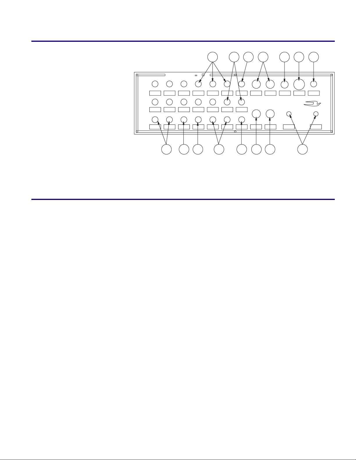
Switch Panel ................................................................ 9
Destination Signs ........................................................ 9
Seats & Seat Belts ...................................................... 10
Electrical Systems ..................................................... 13
Light Bulb Data ......................................................... 14
Doran Warning Light Monitor ................................ 15
Circuit Breakers ......................................................... 19
Mirrors & Mirror Adjustment ................................. 20
Emergency Equipment............................................. 22
Emergency Exit ......................................................... 24
Transpec Safety Vent ................................................ 24
Wheelchair Lifts ........................................................ 25
Stop Arms .................................................................. 25
Front Access ............................................................... 28
Access Doors ............................................................. 29
Body Tie Down.......................................................... 29
Towing or Pushing ................................................... 30
Doors .......................................................................... 30
Vandal Locks ............................................................. 34
Keeping Your Vehicle Looking New ...................... 35
Engine Access ............................................................ 36
Heaters ....................................................................... 38
Windows & Windshields ......................................... 45
Windshield Wipers ................................................... 49
Lower Side Panel Repair Procedure ...................... 50
Spare Tire Location & Removal .............................. 50
Tires, Wheels & Rims ............................................... 52
Jacking Instructions .................................................. 54
Engine Operating Instructions................................ 54
Noise Emissions Warranty ...................................... 56
Fuel & Lubricant Requirements ............................. 57
Compressed Natural Gas ........................................ 57
Manual Five Speed Transmission........................... 65
Allison Automatic Transmission ............................ 65
Two Speed Rear Axle Shift Control ........................ 70
Air Brakes .................................................................. 73
Hydraulic System ..................................................... 75
Hydraulic Clutch Controls &
Adjustment for Manual Transmissions ............ 77
Radiator Fans............................................................. 78
Shutters ...................................................................... 79
Cooling System ......................................................... 79
All American Pitman Arm....................................... 79
Front Axle Stop & Steering Gear
Automatic Poppet Adjustments ........................ 80
Wheelbearing Adjustments ..................................... 81
Rear Axle Vent ........................................................... 81
Ridewell Vehicle Air Suspension ............................ 82
Scheduled Maintenance ........................................... 86
Maintenance Service Keys ....................................... 89
Quick Reference Maintenance Charts.................... 90
Cummins Engine Maintenance Chart ................... 90
John Deere 8.1 CNG Engine Maint. Chart ............ 91
Suspension Maintenance Chart .............................. 92
Engine Belt Chart ...................................................... 92
Axle Maintenance Chart .......................................... 93
Brake Maintenance Chart ........................................ 94
Chassis Component Maintenance Chart ............... 95
Body Component Maintenance Chart ............. 96, 97
Wheelchair Lift Maintenance Chart ....................... 97
General Data .............................................................. 98
Index ........................................................................... 99
TABLE OF CONTENTS

2

3
INTRODUCTION
Thank you for selecting the Blue Bird All American. Your All American is the result of mass transporta-
tion developments, which have been ongoing since 1927. The design and construction of the All American
reflects Blue Bird’s concern for efficient, and above all, Safe Operation.
This manual has been prepared to acquaint you with various aspects of service, maintenance and opera-
tion. It explains the various features and controls which should be familiar to the operator before he/she
attempts to drive the unit and will help keep your Blue Bird All American in top operating condition and help
extend its service life.
Your Blue Bird All American may have all or some of the equipment described in this manual. Therefore,
you may find maintenance data for equipment not installed on your bus. Text, illustrations and specifications
in this manual are based on information available at the time of printing. We reserve the right to make
changes at any time without notice. To obtain maintenance and parts information, refer to Blue Bird Chassis
Maintenance Manual and Parts Catalog. You are encouraged to contact your Blue Bird distributor, if addi-
tional maintenance information or assistance is needed.
The complete line of Blue Bird Service Parts is available from your Blue Bird distributor. The use of origi-
nal Blue Bird replacement parts and components will help insure that the design features inherent in the All
American remain for the life of the vehicle.
Proper operation, service and maintenance is important to the safety and reliability of all motor vehicles.
The information contained herein is provided as a reference for systems and components that require peri-
odic service. The intervals given are manufacturer’s recommendations and should be considered maximum
intervals. Actual operating conditions must be considered and maintenance intervals adjusted accordingly.
Anytime a system does not perform satisfactorily, corrective service should be performed at once.
Familiarity with automobile operation and controls is not a prerequisite, but is assumed to be common
knowledge to all who will be operating this coach. Basically, control and operation of both are the same, but
some distinct differences must be recognized before operation of the coach is attempted.
Remember: The bus is 8 feet wide without outside mirrors and is 25 to 40 feet long. Therefore, it is 2 feet
wider and 2 to 3 times as long as the average automobile. The driver sits in front of the wide track front axle,
so the steering has a completely different feel. Acceleration will very likely be slower than that of an automo-
bile. The feel of the brakes may differ from that which is familiar to the new operator. This makes it very
important, from a safety standpoint, for him or her to become completely familiar with that function through
experience before attempting passenger transit. The operator will observe other differences, but after acquir-
ing basic familiarization and some practical experience, he will find the operation quickly becomes quite
natural, comfortable and far from difficult.
CAUTION: No one should attempt to operate this coach without a thorough knowledge of all instruments
and controls, without having had actual driving experience in this or a similar vehicle under supervision,
and without having the appropriate license or permit to operate it. Do not drive the coach until the space
in front, on the sides and in the rear is unobstructed. Most accidents occur because the operator did not
ensure that there was no one in the way before driving.
This manual should be read before the operator attempts to drive the unit.
This manual provides you with the most current maintenance and operation information. We welcome
your comments and suggestions regarding this manual. All correspondence should be directed to the Techni-
cal Services Department of Blue Bird Body Company, P.O. Box 937, Fort Valley, GA, 31030, Attn: TECHNICAL
SERVICES.

4
FOREWORD
This Operator’s Manual provides some general, as well as specific, information regarding safe operation
and maintenance of your Blue Bird bus. It does not address all items or situations that may arise and is not a
substitute for proper driver and mechanic training. The exercise of care, common sense and good driving and
working practices are required for safe operation.
If specific questions or concerns arise that are not adequately addressed in this manual, please contact
your Blue Bird distributor. The distributor will answer your questions or put you in contact with the proper
factory personnel.
Throughout this guide you will find CAUTIONS and WARNINGS. CAUTIONS are given to prevent
you from making an error which could damage the vehicle and possibly cause personal injury. WARNINGS
remind you to be especially careful to avoid personal injury.
Blue Bird Corporation offers many items as standard and optional equipment to meet state, federal and
local specifications and individual customer requirements. Properly selected equipment can help insure
reliable and safe transportation of passengers.
Some examples of this safety equipment are: stop arms, crossing guards, warning lights, warning light
monitors, mirrors, first aid kits, fire extinguishers, warning reflectors, fusees, directional and brake lights,
warning buzzers, vandal locks, emergency exits and seat belts.
It is the driver’s responsibility to insure that the safety items are in proper order. Equipment relating to
safety should be checked for operation on a daily basis. Safety equipment may vary due to state and federal
specifications, and individual customer requirements.
In addition, the driver/operator must insure that the loading area around the bus is clear of pedestrians
before stopping and that all unloaded passengers are a safe distance away from the bus before moving.
REPORTING SAFETY DEFECTS
If you believe your vehicle has a safety defect which could cause a crash or could cause injury or death,
you should immediately inform the National Highway Traffic Safety Administration (NHTSA) in addition to
notifying Blue Bird Corporation.
If NHTSA receives similar complaints, it may open an investigation and, if it finds that a safety defect
exists in a group of vehicles, it may order a recall and remedy campaign. However, NHTSA cannot become
involved in individual problems between you, your dealer or Blue Bird Corporation.
To contact NHTSA you may either call the Auto Safety Hotline toll free at 1-800-424-9393 (or 366-0123 in
Washington, D.C. area), or write to: NHTSA, U.S. Department of Transportation, Washington, D.C. 20590.
You can also obtain other information about Motor Vehicle Safety from the hotline.
COACH IDENTIFICATION
The Vehicle Certification Plate certifies that the vehicle
conforms to all applicable Federal Motor Vehicle Safety Stan-
dards in effect at the date of manufacture. Do not remove or
deface this plate.
MANUFACTURED BY
BLUE BIRD BODY COMPANY
DATE OF MFR.
INC. VEH. MFG. BY DATE
SUITABLE TIRE - RIM CHOICE
GVWR
GAWR : FRONT
GAWR : REAR WITH TIRES
PSI COLD SINGLE
PSI COLD DUAL
WITH TIRES
RIMS, AT
RIMS, AT
THIS VEHICLE CONFORMS TO ALL APPLICABLE FEDERAL
MOTOR VEHICLE SAFETY STANDARDS IN EFFECT IN
CLASSIFICATION
V.I.N.

5
The Body Serial and Service Number Plate is located on
the front upper inner panel above the windshield. Refer to
the data on this plate for registration purposes or for replace-
ment part information.
The Axle Record and Chassis Service Number Plate is
located on the front upper inner panel above the windshield.
Refer to the data on these plates for registration purposes or
for replacement part information.
INSPECTION
PRIOR TO PLACING THE NEW BUS IN SERVICE, PERFORM THE FOLLOWING:
• Check suspension u-bolt torque.
• Check Ridewell suspension torque.
• Check brake adjustment.
• Check body tie-down bolts torque.
DAILY INSPECTION
In order to keep your bus in the best operating condition from the standpoint of safety, convenience,
service and operating expense, it is recommended the following inspection procedures be followed on a daily
basis. Any malfunctions or defects should be corrected before the next trip. Report needed services to respon-
sible maintenance personnel.
• Check fuel level.
• Drain air tanks (cold weather).
• Check engine oil level.
• Check coolant level.
• Check automatic transmission fluid level.
Look outside the bus:
• Windshield, mirrors, front windows, head, tail, directional, and stop lights - wipe clean.
• Exhaust - tailpipe clear?
• Rear emergency door, open and close, check warning buzzer operation.
• Tire pressure and tread, OK? Lug nuts in place?
• Drain air brake tank.
• Look under bus - all clear?
• General outside appearance, clean for school bus identification?
• Mirrors - clean and adjusted?
BLUE BIRD
BODY CO.
FORT VALLEY, GEORGIA
BODY NO.
CAPACITY
MODEL YEAR
BODY SERVICE NO.
CHASSIS
SERIAL
FURNISH INFORMATION BELOW WHEN ORDERING AXLE PARTS
FRONT
AXLE
BRAKE
DRUM
REAR
AXLE
ENGINE
SERIAL
BRAKE LINING FMSI
NO.& FRICTION CODE
BRAKE LINING FMSI
NO.& FRICTION CODE
BRAKE
DRUM
REAR AXLE RATIO
CHASSIS SERVICE NO.

6
Look inside the bus:
• Seat, floor - housekeeping. Steps and aisle clear?
• Emergency exits open & close, rear door, windows.
• Emergency equipment.
• Fire extinguisher pressure.
• First aid kit.
• Driver’s area - windshield, windows clean?
• Mirrors - clean and adjusted?
• Emergency doors/windows unlocked and operate freely?
• Do buzzers activate when exits are not fully latched?
Starting the engine:
• Be sure parking brakes are on.
• Put in Neutral.
• With key on, check: Fuel gauge OK? Check brake warning buzzer or light, neutral safety switch.
• Start engine - look, listen for trouble signs, check gauges.
With the engine running, check (from driver’s seat):
• Mirrors, interior and stepwell lights, service door seal.
• Steering feel OK? Noise?
• Horn, defroster & heater blower, windshield wiper operation.
• Brakes - pedal height & feel, gauge reading OK? Parking brake release, reset.
Outside checks required before you drive away:
• Turn signals - right & left, front & rear - clean & flashing?
• Flasher warning lights - front & rear - clean & flashing?
• Stop arm (if used) - clean & working?
• Headlights hi-lo beams.
• Stoplights & taillights - clean & working?
• Hazard flasher working?
Final check as you move the bus:
• Seat belt fastened?
• Brakes - Stop & hold?
• Steering feel OK? Unusual noises? Bus under control- tracking straight?
• Brake to a stop. All gauges OK?
Remember: Safety on the road also depends on you. Observe weather and road condition and drive
accordingly. Be physically and mentally alert. When backing in vicinity of congestion or pedestrians use
outside monitor or director. Look around before driving away from where you are parked and observe all
traffic rules and regulations.
WEEKLY INSPECTION
• Drain air tanks (warm weather).
• Check tires.
• Inspect seat cushion attachments for tightness.
• Inspect seat belts and buckles.
• Check fuel water separator.
• Check windshield washer fluid level.

7
OPERATOR’S COMPARTMENT
1. Driver’s seat.
2. Switch panel.
3. Windshield wiper switch - op-
erates windshield wiper &
washer.
4. Driver’s window defroster - di-
rects air flowto driver’s window
5. Driver’s foot warmer, window
defroster control - controls flow
of air.
6. Horn button - sounds electric
horn.
7. Instrument panel.
8. Hazard signal switch - activates
emergency warning systems.
9. Parking brake - prevents unit
from rolling when parked.
10. Automatic transmission shift
control (range selector).
11. Driver’s fresh air controls - operates driver’s fresh air
vent.
12. Accelerator pedal - controls engine speed.
13. Brake pedal or air treadle - applies service brakes.
14. Dimmer switch - selects headlight high or low beam.
15. Tilt and telescoping lever.
16. Hand throttle - raises engine idle speed. (AAFE only)
WARNING: Do not use throttle lock as means of cruise
control. Always release throttle lock before putting
vehicle in motion.
17. High beam - indicates headlights on bright.
18. Low air - warning indicates air pressure
in system is low.
19. Blanks - for optional indicators.
20. Engine warning - indicates low oil pres-
sure or high water temperature.
21. Refill sander - warning, level of sand in
sanders is low.
22. Right turn indicator.
23. Left turn indicator.
NOT ILLUSTRATED
• Door control.
• Wig-Wag - low air pressure warning.
• Reservoir drain valve.
• Warning light monitor - indicates whether
warning lights are working.
• Inside mirror.
1
2
34 567
8
9
10
11
12
13
14
16
15
• Driver’s arm rest.
• Turn signal lever - operates turn signals.
• Fresh air control for front heaters - operates
fresh air vent.
• Fusee canister.
• Reflector flares and flags.
• PA system - used to address.
ENG
WARN LOW
AIR REFILL
SANDER
23 19 17 18 21 2220 19

8
TILT & TELESCOPING STEERING
To adjust steering wheel position, use the tilting lever located on
the left side of steering mounting bracket. Press lever downward to
unlock steering column. Move column to one of four positions and
release lever. To raise or lower the steering wheel position, pull up
on the tilting lever. This will enable you to raise or lower the steering
wheel to one of its seven positions.
INSTRUMENT PANEL & CONTROLS
INSTRUMENT PANEL WITH DUAL SCALE GAUGES
The speed indicator is measured in miles per hour and kilometers per hour. All temperature gauges are
measured in degrees Fahrenheit and degrees Celsius. All pressure gauges are measured in pounds per square
inch and kilopascals (kilo newtons per square meter).
1. Speedometer - indicates ve-
hicle speed.
2. Air pressure gauge, front -
indicates air system pressure.
3. Air pressure gauge, rear -
indicates air system pressure.
4. Tachometer with hourmeter
- indicates engine RPM.
5. Voltmeter - indicates electri-
cal system voltage.
6. Ammeter - indicates battery
charge and discharge, op-
tional.
7. Water temperature gauge -
indicates engine coolant tem-
perature.
8. Oil pressure gauge - indicates oil pressure.
9. Fuel gauge - indicates fuel supply.
10. Headlight switch - turns on headlights.
11. Dash light dimmer - dims lights in instruments.
12. Air Control Accelerator - increases engine RPM. (AARE only) (see ENGINE HIGH IDLE SWITCH)
13. Transmission Oil Temp Gauge - indicates transmission oil temperature.
WARNING: In the case of an air reserve failure, the low air pressure warning buzzer will sound and
warning light illuminate, giving an indication that trouble is evident and the respective air gauge located
on the dash will indicate which system has lost air pressure. The coach must not be operated under those
conditions, but must be repaired before continuing operation.
Tilt Lever
RPM X 1000
HOURS
0
0
0
0
0
0
0
MPH
Miles
0
0
0
0
0
0
0
FRONT AIR BRAKE
75 100
125
150
0
25
50
100-
0
+100
AMPS
160 200 240
TRANS
OIL
40 90 140
810 12 14 1618
VOLTS
OIL
0120
30 60
8
24
REAR AIR BRAKE
75 100
125
150
0
25
50
180 200 220
TEMP
40 90 125
ALIGN SEAT WITH
STEERING WHEEL
BEFORE OPERATING
VEHICLE
AIR
CONTROL
ACCEL
E1/2
F
FUEL
DASH
LIGHTS
12 591 47
10 13 6 211 3 8

9
SWITCH PANEL
1. Underseat Heater
2. Dome
3. Clearance Lamps
4. Warning Light Pilots
5. Manuals
6. Master
7. Heater Pump
8. Auxiliary Heater
9. Front Heater
10. Defroster
11. Fan
12. Wash/Wipe
13. Entrance Door
14. Exit Door
15. Pilot Light
DESTINATION SIGNS
Hinged Sign Front - Mounted on outside of front roof cap with internal control for changing sign. Peri-
odically lubricate hinges and lever assembly with lightweight lubricating oil.
Hinged Sign Rear - Mounted on outside of rear roof cap, manually changed from outside. Periodically
lubricate hinges with lightweight lubricating oil.
One Station Lighted Curtain - Replace bulbs as needed. May occasionally loosen and cause slack in the
curtain due to vibration. To tighten curtain, loosen bolts, pull curtain tight, retighten bolts.
Roller Destination Sign with Lighted Curtain - Replace bulbs as needed. May occasionally require same
adjustment as One Station Sign. Periodically lubricate roller gears with light grease, such as "White Lube,"
and hinges on access door with lightweight lubricating oil. To change sign, turn crank located on front upper
inner panel above windshield to desired destination.
Two Station Sign - Front lighted, sign material masonite with lettering on both sides. Lubricate interior
door hinge on front upper inner panel with lightweight lubricating oil.
Lighted “School Bus” Sign - Back lighted yellow plexiglass sign. Replace bulbs as needed. Lubricate
interior door hinge on front upper inner panel with lightweight lubricating oil.
NOTE: All maintenance procedures to be done at 6 months or 6,000 mile intervals, whichever occurs first.
BLANK BLANK BLANK DOME DOME DOME CL LAMPS WL PILOT WL PILOT
WL MANUAL WL MASTER
BLANK
BLUE BIRD
BODY COMPANY
FANFANBLANK BLANK BLANK BLANK BLANK
US HTR US HTR AUX HTR
HTR PUMP
FRT HTR FRT HTR
DEFROST
EXIT DOOR ENT DOOR
WASH/WIPE WASH/WIPE
LO HIPULL/ON PUSH/OFF
1
234 56
7
8910
11
12
13
14
15

10
SEATS & SEAT BELTS
DRIVERS SEAT
1. Weight & Height Adjustment -
To adjust, push valve knob in to
raise seat and pull out to lower
it. When adjusted properly, the
seat should not top nor bottom
against the end limits of the ver-
tical travel under normal driv-
ing condition. Adjustment po-
sition should also provide for
driving visibility and vehicle
control.
2. Fore & Aft Adjustment - Hold
lever to the left to adjust seat
position forward or backward.
3. Back Angle Adjustment - Lean
forward slightly to remove pres-
sure from seat back. Hold
handle rearward to adjust to any
position within range.
4. Cushion Tilt Adjustment - Rotate
seat tilt knob to decrease or to
increase seat tilt.
5. Lumbar Adjustment - Rotate
knob forward to increase or rear-
ward to decrease the support in
the lumbar area.
WARNING: Do not attempt to adjust seat while vehicle is in motion. Do not adjust height adjustment
while sitting in driver’s seat. Keep feet and other items away from height adjustment handles and pedals
while vehicle is in motion.
DRIVER'S SEAT LUBRICATION
NOTE: For optional Blue Bird driver's seat.
Moving parts of the driver’s seat require lubrication for ease of operation, as well as, longevity of the seat
and prevention of excessive wear.
Currently available white lithium-based grease in an aerosol can, gives excellent coverage, when care-
fully directed into moving part joints. The very light coating of lubrication provided by aerosol-carried sol-
vent-type solution works very well for penetrating into a joint and cleaning away dirt, but should only be
depended on for lubrication, if frequently applied. A common 10W30 or 10W40 motor oil will provide good
lubrication.
Remember that all moving part joints, tilt pivots, slide forward/back adjustment and vertical motion
pivots (4 total) require lubrication. This should be done every six months or 6,000 miles, whichever occurs
first, with a lithium-based grease in aerosol form.
123 45
LUMBAR
ADJUSTMENT
BACK ANGLE
ADJUSTMENT
FORE & AFT
ADJUSTMENT
CUSHION TILT
ADJUSTMENT
HEIGHT
ADJUSTMENT

11
DRIVER’S SEAT BELT OPERATION
Driver’s seat belt should be worn at all times when the vehicle is being driven.
Blue Bird driver’s seat belts have automatic locking retractors and are self-adjusting. They also have an
anti-cinch device which prevents the belt from uncomfortable tightening as you drive. To use, withdraw
ample length of belt from retractor or retractors to allow engagement of buckle halves. Engage buckle halves
and allow retractor to withdraw belt to a snug fit. Attempt to pull belt from retractor after it has been with-
drawn to assure the automatic locking mechanism is operating properly.
The buckle can be released by pushing button in center of buckle.
DRIVER’S SEAT BELT WITH SHOULDER HARNESS (If so equipped)
Driver’s seat belt should be worn at all times when the vehicle is being driven.
Driver’s seat belt shoulder harness is emergency locking; lap belt may be either emergency locking or
automatic locking depending on the option chosen. The emergency locking retractor used for all shoulder
harnesses and specified lap belts is dual sensitive. Emergency locking retractor engages when the vehicle tips
15 degrees or more or if belt speed exceeds a preset rate. Automatic locking retractors for specified lap belts
are self adjusting. Adjust the shoulder belt bracket upward for taller drivers, downward for shorter drivers
or until maximum comfort is achieved.
To use, withdraw ample length of belt from retractor or retractors to allow engagement of buckle halves.
Engage buckle halves and allow retractor to draw belt to a snug fit.
The buckle is released by pushing the button in the center of the buckle.
PASSENGER SEAT BELT OPERATION (If so equipped)
Individual lap belts for passengers are retractable or non-retractable depending on option ordered. Insert
the catch into the buckle, test for assurance of latch fit and pull loose end of strap until belt fits snugly across
the lower hips. The buckle can be released, by pushing button in center of buckle. The adjustable end can be
moved outward on its strap by turning 90 degrees to the strap and pulling.
SEAT BELT INSPECTION & MAINTENANCE
Inspect seat belts and their attachments on a weekly basis. Check seat belt buckles and adjustability to
insure proper operation. If necessary, lubricate buckle with a graphite lubricant. When buckle is found to be
inoperable, replace immediately. If there are any defects in the webbing (i.e. torn or frayed), the seat belt must
be replaced as soon as possible to ensure passenger safety. Hand wash webbing with warm water and mild
soap. Rinse thoroughly and dry in the shade. Do not bleach or redye, because such processing may severely
weaken the assembly.
WARNING: Be sure the lap belt is fitted snugly around the hips, not the waist. Failure to do so may
increase the chance of injury in the event of a collision. Do not bleach or redye, because such processing
may severely weaken the assembly.
SEAT INSPECTION & MAINTENANCE
Blue Bird seats are built to meet Federal Motor Vehicle Safety Standards. In order to provide even safer
passenger transportation, the following guidelines should be met.
1. Inspect and retighten seat leg and wall side mounting bolts every 90 days.
2. Inspect and retighten cushion attachments with a Phillips head screwdriver on a weekly basis.
3. Inspect upholstery for cuts and tears every 90 days. If torn, remove upholstery by removing the staples
at the bottom front of seat back or bottom of cushion and remove cover. For installation of new cover,
reverse this procedure.
4. School bus seats are equipped with a special foam back pad. Should this pad ever become damaged,
it should be replaced with an approved replacement part. Aftermarket suppliers do exist and should
be checked for compliance with federal standards.

12
SEAT CARE AND CLEANING
It is imperative that the interior of the bus be kept clean and seats are an important part of this mainte-
nance. Regular cleaning and care will prolong the life of the seats and improve the general appearance.
Everyday dirt and soil - Most everyday soil and dirt may be removed with a soap and water solution. If
the stain is persistent, a stiff bristle brush may be used. Fabric covered seats should be rinsed with clean water
after stain is removed.
Paint, tar and asphalt - Remove stain immediately using a damp cloth and kerosene. Rub the stain
gently, using small strokes. Rinse thoroughly. NOTE: This type of stain may become permanent if not cleaned
immediately.
Nail polish and lacquer-based stains - Soak up as much as possible with dry cloth immediately. Any
remaining stain may be removed with a nonflammable cleaning fluid such as “Tuff Stuff” or “Armorall”
cleanser. Rinse thoroughly with clean water.
Gum, grease and shoe polish - Remove as much as possible immediately. Shoe polish if left for any
length of time will permanently stain. Clean any remaining stain with “Tuff Stuff” or “Armorall” cleanser.
Ink - Remove stain immediately using a damp cloth and alcohol.
SEAT CUSHION REMOVAL & INSTALLATION - DOT SEATS
WARNING: If seat cushions are removed for maintenance, they must be reinstalled using the following
instructions. Failure to comply with these instructions could result in injury from unattached seat cush-
ions in the event of an accident.
REMOVAL
1. Loosen the two front swivel type clamps at the front underside of the cushion with a phillips-tip
screwdriver. Caution: Do not remove clamps.
2. Rotate the swivel clamps so as to clear the front retaining channel frame.
3. Lift the forward edge of cushion 2 to 3 inches and pull cushion forward to remove.
INSTALLATION
1. Place the rear edge of cushion down on the base portion of the seat frame. Lifting the forward edge 2
to 3 inches, slide the cushion to the rear to engage the positive type clamp into the rear retaining
channel.
2. Lower the forward edge to the frame, making sure the swivel clamps are inside the frame and the
positive type clamps are secure on the rear retaining channel.
3. Rotate the swivel clamp to engage the forward retaining channel frame.
4. Tighten with phillips-tip screwdriver until clamps do not rotate.
SEAT CUSHION REMOVAL & INSTALLATION - DOT SEAT BELT SEATS
REMOVAL
1. Loosen the two front swivel-type clamps at the front underside of the cushion with a phillips-tip
screwdriver. Caution: Do not remove clamps.
2. Rotate the swivel clamp located at the rear underside of seat cushion.
3. While lifting the rear edge of the cushion, pull the cushion to the rear and remove.
INSTALLATION
1. Place the forward edge of the cushion 2 inches to the rear of the front retaining channel. Slide the
cushion forward, engaging the positive clamps onto the forward retaining channel.
2. Lower the rear edge to the frame and rotate the swivel clamps so they engage the square tube
crossmember.
3. Tighten screws in front and rear clamps with phillips-tip screwdriver until clamps do not rotate.

13
TRACK MOUNTED PASSENGER SEATS
If your bus is equipped track mounted passenger seats and you relocate the seats or remove the seats to
accommodate wheelchairs, you must follow rules of spacing and placement to comply with FMVSS 222
"School Bus Passenger Seating and Crash Protection" and FMVSS 217 "Bus Window Retention and Release".
The decal (as shown) which gives these rules is installed on the interior body panel above the windshield.
All passenger seats must have a seat or barrier in front of it to provide compartmentalization required by
Federal Motor Vehicle Safety Standards. As you reconfigure your bus, you may need additional barriers.
Barriers are available from Blue Bird Body Company Part Sales.
FEDERAL STANDARD REQUIREMENTS FOR TRACK SEAT PLACEMENT
ALL PASSENGER SEATS MUST HAVE A SEAT OR BARRIER
THE SAME WIDTH AS THE SEAT IN FRONT OF IT
12.00 12.00
2.00
27.00 MIN.
31.00 MAX. 11.00 MIN.
15.00 MAX.
SEAT SPACING MEASURED
AT AISLE
REAR SEAT PLACEMENT - DRIVER'S
SIDE. (REAR SEAT ON ENTRANCE
DOOR SIDE MAYTOUCH BODY.) SIDE EMERGENCY DOOR
CLEAR AISLE EMERGENCY EXIT
RELEASE CLEARANCE
ELECTRICAL SYSTEMS
The following guidelines must be followed when doing any work on vehicle electrical components or wiring.
1. Before beginning any electrical work, disconnect all batteries.Always remove all battery ground straps
first and replace last to prevent accidental arcing.
2. Use only proper gauge wiring with high temperature insulation, such as, chemically cross-linked
polyethylene, which meets SAE J-1128 (150 Degree Celsius).
3. Be certain any added circuit is protected by the use of a fuse or circuit breaker.
4. Any push-on terminal must be insulated.
5. When installing or replacing any wiring (other than ground straps), observe the following:
A. Always use clamps to secure wires away from any sharp metal edges or moving components.
B. Support wires at least every 30 inches with insulated clamps.
C. Where wiring is connected to moving component such as the engine, provide an adequate slack
loop to allow for motion in all directions. Clamp at both sides of loop.
D. Be certain there is sufficient length in wires so no wires are pulled in tension.
E. Wires should be secured to remain four inches from exhaust pipes, manifolds or turbochargers
unless components are shielded.
F. Use rubber grommets whenever wires must pass through holes.
G. Cover all full time hot or accessory and ignition hot wires with approved loom.
H. Avoid routing wires in contact with fuel lines or plastic components.

14
6. Always be sure ground straps are replaced when any work is done on engine components. The
alternator must have at least a six (6) gauge strap. The engine must have one strap, engine block and
transmission. (Use bolt that mounts transmission to rear face of engine block.) Allow slack loop for
engine motion. Use external star tooth washer between cable and frame.
7. Do not “splice” into existing wires, instead route wire full length to appropriate source.
8. If accessories must be added, relays may be required; check installation instructions thoroughly. Use
bank of circuit breakers in the electrical panel unless the accessory must be on during cranking, in
which case the “hot bar” should be used.
9. Always use insulated rubber boots over hot six (6) gauge wiring on alternator, ammeter shunt or
junction blocks.
Quick Reference
Wiring Circuit Color Code Major Circuits
FUNCTION COLOR
Left Rear Directional Light Yellow
Right Rear Directional Light Dark Green
Stoplights Red
Back-up Lights Blue
Taillights Brown
Ground White
Ignition Feed, Primary Feed Black
Refer to the master wiring diagram for wire colors for other circuits.
LIGHT BULB DATA
Lamp Description Trade Name Trade No. Color Bulb No.
INTERIOR LIGHTS
Dome Weldon 8005 (Standard) 89
Weldon 8010 (Deluxe) 93
Stepwell Arrow 35 67
Emerg. Door Light Weldon 8025 67
Switch Panel Pilots Cole Hersee PL19 53
Dial 41204-1211 68
Switch Panel Illum. 1314962 53

15
EXTERIOR LIGHTS
Directional KD 772-9105 1156
Weldon 1010 Series Red & Amber
Plain & w/Arrow 1156
Signal Stat 1604 1156
Guide 3111-04 Amber 1156
Warning Light Weldon 1020-Series Red & Amber 4636
Cluster & Marker Weldon 5050 Amber & Red 904
Peterson 122 Amber & Red 194
Side Directional Peterson 122 194
Arrow 059-9900021CP 1073
Stop-Tail/Tag Dominion 70-6128-71 1157
Signal Stat 2103 1157
Back-UP KD 854-5301 1156
Weldon 7-1010-1 1156
Wekdon 3-1060-1100 1156
Stop Weldon 1010 Red 1156
Arrow 438 1157
Signal Stat 1605 1156
KD 772-9105 1156
Destination Sign 89
School Bus Sign TS93
DORAN WARNING LIGHT MONITOR
The Doran monitor is a current-monitoring device; therefore, if current is flowing through one of the bus
lamp circuits, the monitor senses this and lights the corresponding monitor bulb. If the bus lamp burns out,
current ceases and the corresponding monitor bulb goes out indicating a fault. (See schematic illustration
Page 18 showing A Typical Monitor Circuit).
The Doran monitor is a reliable, long-life device, but as with most electrical instruments, it can be over-
heated and damaged if an overload occurs in a bus light. Such overloads can exist if a bus light circuit
becomes shorted, forcing current through a coil in the monitor which exceeds its rated capacity. Short circuits
can occur if improper connections are made during installations, during bus repairs, etc. If the monitor has
an optional thermistor overload protection, the tail light circuits are overload protected (thermistors are lo-
cated on the bottom of the component side of the P.C. Board).
This repair instruction is intended to assist qualified repair personnel to diagnose, remove, repair and
reinstall monitors, which have become inoperative due to a variety of conditions.
REPAIR PROCEDURE
NOTE: Field repair is not intended for monitors covered by Blue Bird Body Company warranty. Inoperative
monitors under warranty should be returned to Blue Bird Body Company for repair or replacement under
the terms and conditions of warranty for electrical parts.
Step 1: MOST IMPORTANT! Carefully note and record exactly which monitor lamps are not operating prop-
erly. Include this information on a tag to be attached to the monitor after removal from the bus panel.
Step 2: Disconnect bus battery.

16
Step 3: Remove mounting screws, which attach the monitor to the bus panel, being careful not to accidently
pull any connecting wires loose.
Step 4: Remove one connecting wire at a time from monitor terminals, tagging EACH WIRE with the termi-
nal number shown on the monitor.
Step 5: If a spare monitor is to be installed at this point, record the monitor serial number for your future
reference. The number is shown on both the protective fiberboard back plate and on the monitor
printed circuit board.
Step 6: With the monitor removed from the bus and to a repair bench, remove the four nuts to remove the
monitor PC board from the face plate. Pull the protective fiberboard backing from the terminals, being
careful not to bend or tear it; retain for later use.
Step 7: Locate the components to be replaced by referring to Diagram of Coils and Reed Switches on Page 16.
Locate the solder points for these components.
Step 8: Replace the inoperative coil/reed switch assembly as follows:
a. With wire clippers cut the reed switch leads (2) and the coil leads (2) as close to the board surface,
as possible. (If a tail lamp monitor is to be replaced, pull the protective shield loose and retain for
reuse later).
b. With soldering iron, CAREFULLY melt-out the remaining coil and reed switch leads from the
solder side of the board, pulling gently on the leads with tweezers. With the lead stubs removed,
touch the holds in the PC board with soldering iron to "clear" them for replacement
lead insertion.
c. Insert replacement coil and reed switch leads, guiding them into proper holes with index finger
and thumb. Hold coil snug to the board while leads are bent over the solder side of the board. It is
recommended that excess leads not be clipped until after soldering is completed. This will help to
minimize shock or vibration on the reed switch, when leads are later trimmed. (Reed switches are
encased in a fragile envelope and should be handled carefully to avoid chipping of envelope or
distortion of leads).
d. Place a bead of solder on the remaining lead ends, being careful not to interfere with other nearby
solder points or PC paths.
Step 9: If a tail lamp has been replaced, clean the original sealant from the protective shields and reinstall
with new Silicone rubber sealant as recommended.
Step10:Visually examine all other components, leads, PC paths and LED’s for any remaining problems to be
corrected. Reinstall monitor in bus, making sure battery is disconnected and that wires are recon-
nected to the monitor in the same order as shown in chart on page 18.
If additional instructions are needed after following the above procedure, contact Blue Bird Body Company.
DIAGNOSIS
Condition A
If ALL lights on the monitor are inoperative, even though the exterior lights on the bus operate properly,
and all connections are still intact, the causes may be:
1. Overloading or physical damage has burnt or broken a path on the printed circuit board. (It is not
considered practical to attempt field repair of printed circuit board paths, and a replacement monitor
is recommended).

17
Condition B:
If a particular light is inoperative, even though the corresponding exterior bus lamp operates properly,
and all connections to the monitor are intact, the cause may be:
1. A burned-out coil or inoperative reed switch. Burned-out coils can usually be visually detected by a
blackened appearance, when the monitor is removed from the bus. If a burned-out coil has not scorched
the board and distorted a PC path, a replacement coil/reed switch kit can be installed. (Available
through your usual Blue Bird service parts source).
2. A loose connection in one or both leads of the light emitting diode (LED) on the monitor. LED’s
seldom fail unless they are installed with incorrect polarity or have suffered physical damage. The
LED recessed design of face plate protects against normal usage. (LED’s CAN be ruined by Ohm
meters, and care must be taken to avoid the use of such meters).
The cause of an inoperative LED will generally be found in monitor and bus circuits other than at the
LED; however, if an LED itself is known to be inoperative, contact your usual Blue Bird service parts source
for special handling of replacement LED’s.
Condition C:
If a monitor light stays on even when the exterior light of the bus is turned off, the reed switch located
inside of the monitor coil is not operating properly. This can be repaired in the field by replacing the coil and
reed switch (available in a preassembled unit from Blue Bird Body Company) - see Condition B, Item 1,
above.
Condition D:
If the tail light monitor and exterior tail lights fail to operate, the cause may be:
1. Tail light bulbs may need to be replaced.
2. An over current situation. In this case, the thermistor has protected the entire circuit. Remove power
from the circuit and monitor, repair over current and reconnect.
Some causes of over current:
A. Dead short,
B. Wrong tail light bulb, and
C. Parallel wiring of additional tail lights.
TOOLS AND SUPPLIES REQUIRED FOR REPAIR
• Hand tools as required to remove mounting screws at bus panel.
• Tags suitable for use in marking connecting wires, and also for recording the monitor problem.
• A 30 or 40 watt soldering iron for electronic repair (do not use a 100-watt “shop” iron).
• Small wire clippers.
• Pointed tweezers (Clauss #225, or equivalent).
• 60/40 resin core solder, .031 or .062 thick (Kester “44” or equivalent).
• Replacement coil/reed switch kits. (Note that coils for bus warning lights are 10-turn coils; those for
tail lamps are 50-turn coils, and those for back-up lights, turn signals, and stop lights are all 16-turn
coils. The proper coil MUST be used in replacement.

18
BUS
BATTERY
BUS FUSE PANEL
OR CIRCUIT BREAKER
QUICK
CONNECT
TERMINAL
COIL
QUICK
CONNECT
TERMINAL
EXTERIOR
BUS LIGHT
QUICK
CONNECT
TERMINAL
#4D (POS.)
REED
SWITCH
RESISTOR
L.E.D.
QUICK
CONNECT
TERMINAL
#4D (POS.)
DORAN EXTERIOR LIGHT MONITOR
(ATypical Circuit)
Monitor
Connection Lamp Function Model: A B C D E
4A RED WARNING LAMP RIGHT INPUT X X X X
1A RED WARNING LAMP RIGHT FRONT OUTPUT X X X X
6A RED WARNING LAMP RIGHT REAR OUTPUT X X X X
2A AMBER WARNING LAMP RIGHT INPUT X X
3A AMBER WARNING LAMP RIGHT FRONT OUTPUT X X
5A AMBER WARNING LAMP RIGHT REAR OUTPUT X X
4B RED WARNING LAMP LEFT INPUT X X X X
1B RED WARNING LAMP LEFT FRONT OUTPUT X X X X
6B RED WARNING LAMP LEFT REAR OUTPUT X X X X
2B AMBER WARNING LAMP LEFT INPUT X X
3B AMBER WARNING LAMP FRONT X X
5B AMBER WARNING LAMP LEFT REAR OUTPUT X X
3C TURN SIGNAL LAMP RIGHT REAR OUTPUT X X X
4C TURN SIGNAL LAMP RIGHT REAR INPUT X X X
2D TURN SIGNAL LAMP LEFT REAR INPUT X X X
3D TURN SIGNAL LAMP LEFT REAR OUTPUT X X X
1C STOP LAMP - INPUT X X X
2C STOP LAMP RIGHT - OUTPUT X X X
1D STOP LAMP LEFT - OUTPUT X X X
7D TAIL LAMP - INPUT X X X
7C TAIL LAMP RIGHT - OUTPUT X X X
8D TAIL LAMP LEFT - OUTPUT X X X
6C BACK-UP LAMP - INPUT X X X
8C BACK-UP LAMP RIGHT OUTPUT X X X
5D BACK-UP LEFT - OUTPUT X X X
CONNECT LAST:
4D 12 V DC POWER X X X X X
6D GROUND X X X X X
5C OPEN X X X X X
Left Tail
Turn Signal
Left Rear Red Warning
Right front Red Warning
Front Left
Amber Warning
Front Left
Amber Warning
Rear Left
Stop
Left Rear
Left Back-Up
Right Back-Up
Right Tail
Amber Warning
Right Rear Amber Warning
Right Front
Red Warning
Rear Left
Red Warning
Right Rear
Stop
Right Rear
Turn Signal
Right Rear
DORAN EXTERIOR LIGHT MONITOR
Diagram of Coils and Reed Switches with Indication of the L.E.D.'s they Control

19
CIRCUIT BREAKERS
Body and chassis circuits are protected by circuit breakers located in a side mounted electrical box below
driver’s window. If a current overload or short should occur in any body circuit, it will trip the circuit breaker.
If a short occurs and the circuit breaker breaks, the circuit breaker will reset itself when the element cools in
about 15 seconds. A short may be indicated by blinking of lights or fluctuating gauges. The shorted circuit
should be corrected immediately. Refer to body or chassis master wiring diagrams provided with vendor
information.
For access to the electrical panel, locate release latch as shown. Push latch release downward. This will
enable the access door located on the outside of bus below the driver’s window to open.
The breakers are divided into three sections: ignition, accessory and hot. The circuit breakers are listed
below by category. For additional information, see Diagram, Wrg, Master Chassis AAFE #1831882 & #1831874
AARE supplied with vendor informatiion per order.
The accessory circuit breakers may have the
following accessories connected:
1. Back-up lights (wire color - Lt. Blue)
2. Backing horn
3. Body solenoid switch
The ignition circuit breaker:
1. Sanders (wire color - Black)
2. Air dryer (wire color - Orange)
3. Fuel transfer valve
4. Heated reservoir drain valve (wire
color - Orange)
5. Racor fuel filter (wire color - Red with
White stripes)
6. Engine warning (wire color - Tan. 12 V
to buzzer.)
7. Low air buzzers (wire color - Tan)
8. Two speed axle
9. Radio
10. PA system
The hot circuit breaker:
1. Headlight switch (wire color - Dark
Green)
2. Stoplight (wire color - Dark Green)
3. Heated fuel filter (wire color - Red)
Release Latch
Driver's Seat
Table of contents
Other Bluebird Bus manuals
Popular Bus manuals by other brands

PREVOST
PREVOST LE MIRAGE XLII BUS SHELLS Maintenance manual

Yutong
Yutong LJ17LLJ user manual

OUMAN
OUMAN ADFWeb HD67029-B2-485-20 manual

Girardin
Girardin Blue Bird Micro Bird 2014 Operation and maintenance guide

ASHOK LEYLAND
ASHOK LEYLAND Optare Tempo X1260 Handbook

Hyundai
Hyundai H350 2016 owner's manual