Shuangri Electric SR618C1 User manual

Installation and Operating Manual
SR618C1
System Regulator for Solar Thermal Systems
Shuangri Electron Co.,Ltd
http//www.shuangri.com
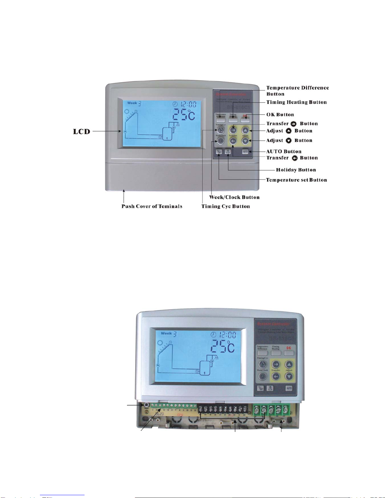
Display illustration
T0-T5 Input ports
6 In
p
uts Output ports
5ou
tputs
AC230V/115V
Reset Button
Shuangri Electron Co.,Ltd
http//www.shuangri.com

Shuangri Electron Co.,Ltd
http//www.shuangri.com
Contents
1. Safety information
1.1 Installation and commissioning
1.2 About this manual
1.3 Liability waiver
1.4 Description of symbols
2. Installation
2.1 Opening/closing controller case
2.2 Installing the controller
2.3 Power connection
2.3.1 Preparation before connection
2.3.2 Terminals connection
3. Commissioning
3.1 Setting the time
3.2 Choosing the solar system
3.3 Operating switch
3.4 Temperature query
4. Device setup
4.1Clock/week
4.2 Systems selection
4.3 System 1
4.4 System 2
4.5 System 3
4.6 System 4
4.7 System 5
4.8 System 6
4.9 System 7
4.10 System 8
4.11 Temperature difference controlling function
4.12 Maximal tank temperature
4.13 Maximal collector temperature
4.14 Collector emergency cut-off
4.15 Protection of collector at low temperature
4.16 Frost protection of collector
4.17 Temperature controlled hot water circulation pump
4.18 Time controlled hot water circulation pump
4.19 Temperature controlled auxiliary heating during three time sections
4.20 Holiday function
4.21 Auxiliary function
4.22 Auto function
4.23 Protection function
5.Troubleshooting
5.1 Trouble protection
5.2 Trouble checking
6.Technical data
Annex: Parameter settings

1. Safety information
1.1 Installation and commissioning
•When laying cables, please ensure that no damage occurs to any of the constructional fire safety measures
presented in the building.
•The controller must not be installed in rooms where easily inflammable gas mixtures are present or may
occur.
•The permissible environmental conditions must not be exceeded at the site of installation.
•Before connecting the device, make sure that the energy supply matches the specifications of controller on
the type plate.
•All devices connected to the controller must conform to the technical specifications of the controller.
•All operations on an open regulator are only to be conducted cleared from the power supply. All safety
regulations for working on the power supply are valid. Connecting and /or all operations that require opening
the regulator (e.g. changing the fuse) are only to be conducted by specialists.
1.2 About this manual
This manual describes the installation, function and operation of a solar thermal controller.
When installing the remaining components e.g. the solar collectors, pump assemblies and the storage unit, be
sure to observe the appropriate installation instructions provided by each manufacturer.
Installation, electrical connection, commissioning and maintenance of the device may only be performed by
trained professional personnel. The professional personnel must be familiar with this manual and follow the
instructions contained herein.
1.3 Liability waiver
The manufacturer cannot monitor the compliance with these instructions or the circumstances and methods
used for installation, operation, utilization and maintenance of this controller. Improper installation can cause
damages to material and persons. This is the reason why we do not take over responsibility and liability for
losses, damages or cost that might arise due to improper installation, operation or wrong utilization and
maintenance or that occur in some connection with the aforementioned. Moreover we do not take over liability
for patent infringements or infringements – occurring in connection with the use of this controller- on third
parties rights. The manufacturer preserves the right to put changes to product, technical date or installation
and operation instructions without prior notice. As soon as it becomes evident that safe operation is no longer
possible (e.g visible damage). Please immediate take the device out of operation. Note: ensure that the
device cannot be accidentally placed into operation.
1.4 Description of symbols
Safety instruction:
Safety instructions in the text are marked with a warning triangle. They indicate measures which can
lead to injury of persons or safety risks.
Operation steps: small triangle “►”is used to indicate operation step.
Shuangri Electron Co.,Ltd
http//www.shuangri.com
Notes: Contains important information on operation or function, is written in blue color
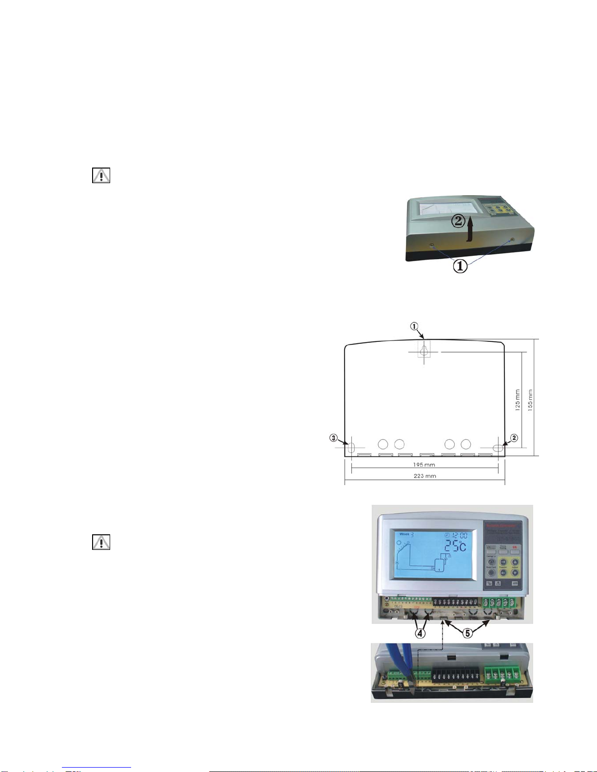
2.Installation
2.1 Opening/closing the case of controller
Danger of electrocution! Before opening the case please ensure power is switched off.
►Loosen the screw ①and remove the upper case ②in an upwards
direction.
►Close the case: insert the hinge grooves of upper case into the retaining
pegs of the lower case.
►pivot the upper case down.
►fasten the case tightly with the screw.
2.2 Installing the controller
Attention: the controller must only be installed in an area having an adequate level of protection.
►Choose a suitable location
Shuangri Electron Co.,Ltd
http//www.shuangri.com
►Drill the upper fastening hole
►Screw in the screw
►Remove the upper case
►Hang the bottom case in the recess ①in picture
►Mark the position of the lower fastening holes ②and
③
►Remove the bottom case again
►Drill the lower fastening holes
►Re-hang the case in the recess ①
►Screw the case firmly using the lower fastening holes
②and ③
►Mount the upper case.
2.3 Electrical connections
Remove the device from the mains supply before opening the
case! All guidelines and regulations of the local electricity
supplier must be observed!
2.3.1 Preparation before connections
Power can only be switched on when the housing of controller is
closed, an installer must make sure that the IP protection class of
the controller is not damaged during installation.
Depending on the type of installation, the cables may enter the
device through the rear of the case ④or the lower side of the case
⑤.

Cable come from the rear ④: remove the plastic flaps from the rear side of the case using an appropriate
tool.
Cable come from the below⑤: cut the left and right plastic flaps using an appropriate tool (e.g. knife) and
break them out of the case.
Notes: the flexible cabling must be fastened to the case using the strain-relief clamps provided
2.3.2 Terminal connection
Shuangri Electron Co.,Ltd
http//www.shuangri.com
Output ports Input ports
Power Connection
1. please note the
type of power
supply required
from the type
plate on the case
of the device
2. The protective
conductor must
be also be
connected
3. Cables type of
H05VV-…..
(NYM…) can be
used
Outputs Inputs
1. Outputs P1& P2: electromagnetic relays
max. switching current:3A
1. Inputs T0 and T1: for PT1000
temperature sensors.
2. Outputs P0/R1,R2: electromagnetic relays,
maximal switching current:5A
2. Inputs T2-T5: for NTC10K
sensors.
3. When using P0 circulation pump,
connection ports are 17 and 18; when
using R1 3-way electromagnetic valve,
connection ports 17, 18 &19. When power is
switched on. Port17 & 18 is shut off; port 17 &
19 is turned on.
4. When using R2 controls circulation pump,
connection ports are 20 and 21; when
using R2 controls 3- way electromagnetic
valve, connection ports 20, 21&22. When
power is switched on. Port 20 & 21 is shut off;
port 20 & 22 is turned on.
5. Output H1: electromagnetic relay, max
switching current 16A.
“Reset”:This button is on the terminal connection panel, when system program is out of working, press
“Reset” to recover the program of system to the factory settings.
Advice regarding the installation of temperature sensors:
Only original factory equipped Pt1000 temperature sensors are approved for use with the collector, it is
equipped with 1.5meter silicon cable and suitable for all weather conditions, the temperature sensor and

cable are temperature resistant up to 280oC, not necessary to distinguish the positive and negative polarity of
the sensor connection.
Only original factory equipped NTC10K,B=3950 temperature sensors are approved for use with tank and pipe,
it is equipped with 1.5meter PVC cable, and they are temperature resistant up to 105oC, not necessary to
distinguish the positive and negative polarity of the sensor connection.
All sensor cables carry low voltage, and to avoid inductive effects, must not be laid close to 230 volt or 400
volt cables (minimum separation of 100mm)
If external inductive effects are existed, e.g. from heavy current cables, overhead train cables, transformer
substations, radio and television devices, amateur radio stations, microwave devices etc, then the cables to
the sensors must be adequately shielded.
Sensor cables may be extended to a maximum length of ca. 100 meter, when cable’s length is up to 50m, and
then 0.75mm2cable should be used. When cable’s length is up to 100m, and then 1.5mm2cable should be
used.
Note: the connection of the pump and sensors depends on the chosen solar system, every port can only
connect one cable, fine core cables should use wire end sleeves.
3. Commissioning
Connect the sensors, pumps or switching valves to the controller before you connect the power
supply!
After switching on power to the controller, firstly it will ask for the “time” to be set and the correct
“solar system” to be chosen.
3.1 Setting the Clock/ Week
After power is switched on, “week 1” “00:00” displays on LCD screen.
►Press “Clock/week” button, hour selection area “00” blinks on display
screen.
►Press “▲”“▼” button to adjust hour of clock
►Press “Clock/week” button again, the minute selection area “00” blinks
►Press “▲”“▼” button to adjust minute of clock
►Press “Clock/week” button again, the week selection “week 1” blinks
►Press “▲”“▼” button to adjust week
After 6 seconds controller confirms the setting automatically, the current time and week are displayed on the
screen.
Shuangri Electron Co.,Ltd
http//www.shuangri.com

3.2 Choosing the solar system
The first solar system displays on the screen, the default setting is System
1.
►Press “OK” button for 3 minutes, “System 1” blinks on the screen.
►Press “▲” select system. 8 systems are available to be chosen (System
1-8).
After 6 seconds controller confirms the setting.
3.3 Operation switch
Manual mode: when operating the device first time, or when testing the function, the outputs of controller can
be operated manually. To do like the following steps:
►Press “Temperature set” button for 3 seconds; the temperature difference controlled circulation pump is
triggered.
►Press “Temperature set” button again, shut off this output.
►Press “ Timing Cyc” button for 3 seconds, the hot water circulation pump is triggered.
►Press “ Timing Cyc” button again, shut off this output.
►Press “ Timing Heating” button for 3 seconds, the auxiliary electricity heating or gas, oil boiler is triggered.
►Press “ Timing Heating ” button again, shut off this output
3.4 Temperature query function
►Press “→” button to check the temperature value of T0-T5 one by one. After 2 minutes, only temperature of
tank is displayed automatically on screen.
Shuangri Electron Co.,Ltd
http//www.shuangri.com

4. Device setup
4.1 Clock/Week display
►Press “Clock/week” button, the hour selection area “00”
blinks on display screen.
►Press “▲”“▼” button to adjust hour of clock
►Press “Clock/week” button again, the minute selection
area “00” blinks
►Press “▲”“▼” button to adjust minute of clock
►Press “Clock/week” button again, the week selection
“week 1” blinks
►Press “▲”“▼” button to adjust week
After 6 seconds controller confirms the setting
automatically, the current time and week are displayed on
the screen.
4.2 Chosen systems
►Press “OK” button for 3 seconds, “System 1” blinks on
the screen.
►Press “▲” select system. Total 8 systems are available to
be chosen. ( System 1-8)
After 6 seconds controller confirms the setting.
4.3 System 1
1 collector array – 1 storage tank – 1 pump
Description:
The solar circuit pump (P1) is switched on as soon as the
switch-on temperature difference between the collector
array (T1) and the storage tank (T2) is reached. If the
temperature difference between the collector array (T1)
and storage tank (T2) drops below the switch-off
temperature difference, or the storage tank (T2) reaches
the maximum storage temperature, then the solar circuit
pump is switched off.
T1: Temperature sensor for collector 1
T2: Temperature sensor in the bottom part of tank 1.
T3: Temperature sensor in the top part of tank ( for control
auxiliary heating)
T4: Temperature sensor on hot water pipe
P1: Solar circuit pump 1
P2: Hot water circuit pump
Note:
•H1 is connected with auxiliary heating, suitable for
system 1 – 8.
•T3, T4, P2 are suitable for system 1-8
•T3 is alternative, when no sensor (T3) is installed in the
top part of sensor, controller will use the signal of sensor
T2 automatically to control the auxiliary heating.
System 1 display
Shuangri Electron Co.,Ltd
http//www.shuangri.com

4.4 System 2
1 collector array – 2 storage tanks – 2 pump
Description:
If the switch – on temperature difference between the
collector array (T1) and one of the two storage tanks (T2,or
T5) is exceeded, then the appropriate solar circuit pump
(P1) or (P0) is switched on. According to the priority
switching, both storage tanks ( T2, T5) are loaded one after
the other, until either the relevant switch-off temperature
difference between the collector array ( T1) and storage
tank (T2, T5) falls below the threshold, or the maximum
storage temperature is reached.
T1: Temperature sensor for collector 1
T2: Temperature sensor in the bottom part of tank 1
T5: Temperature sensor in the tank 2
T4: Temperature sensor on hot water pipe
P1: Solar circuit pump 1
P0: Solar circuit pump 2
Note: the default priority tank is tank 1.
System 2 display
4.5 System 3
1 collector array – 2 storage tanks – 1 pump- 1
valve
Description:
If the switch – on temperature difference between the
collector array (T1) and one of the two storage tanks (T2,
T5) is exceeded, then the solar circuit pump (P1) is
switched on and the switching valve ( R1) is set to the
correct position depending on the storage tank to be
loaded. According to the priority switching, both storage
tanks ( T2, T5) are loaded one after the other, until either
the relevant switch-off temperature difference between the
collector array ( T1) and two storage tanks (T2, T5) falls
below the threshold, or the maximum storage temperature
of T2 or T5 is reached.
T1: Temperature sensor for collector 1
T2: Temperature sensor in the bottom part of tank 1
T5: Temperature sensor in the tank 2
P1: Solar circuit pump 1
R1: 3-way switching valve ( Ports 17,18 are shut off, Ports
17,19 are turned on )
Note: When no voltage is on the system, the switching
valve ( R1) must be set to storage tank 1( T2)
•The default priority tank is tank 1.
System 3 display
Shuangri Electron Co.,Ltd
http//www.shuangri.com

4.6 System 4
2 collector arrays( east/west roof) – 1 storage
tank – 2 pumps
Description:
If the switch – on temperature difference between the
storage tank ( T2) and one or the other of the collector
array ( T1,T0) is reached, then the solar circuit pump (P1)
for collector array 1 (T1) or solar circuit pump (P0) for
collector array 2 ( T0) is switched on, depending on where
the temperature difference occurs. If the switch-on
temperature difference is reached for both collector arrays
(T1, T0), then both pumps (P1, P0) are switched on. The
pumps switch off independently of each other. When either
the relevant switch off temperature difference between one
or both of collector arrays ( T1, T0) and the storage tank
( T2) falls below the threshold, or the maximum storage
temperature is reached, and then the corresponding circuit
pump is switched off.
T1: Temperature sensor for collector 1
T0: Temperature sensor for collector 2
T2: Temperature sensor in the bottom part of tank 1
P1: Solar circuit pump 1
P0: Solar circuit pump 2
System 4 display
4.7 System 5
2 collector arrays( east/west roof) – 1 storage tank
– 1 pump – 1 valve
Description:
The solar circuit pump ( P1) is switched on as soon as the
switch – on temperature difference between one of the two
collector arrays ( T1, T0) and storage tank 1( T2) is
exceeded, the switch valve R1 is always set so that flow
occurs through the warmer of the two collector arrays ( T1,
T2). The pump P1 switches off as soon as the switch-off
temperature difference between the two collector arrays
( T1, T0) and the storage tank ( T2) falls below the
threshold or the maximum storage temperature is reached.
T1: Temperature sensor for collector 1
T0: Temperature sensor for collector 2
T2: Temperature sensor in the bottom part of tank 1
P1: Solar circuit pump 1
R1: 3-way switching valve ( Ports 17,18 are shut off, Ports
17,19 are turned on )
Note:
When no voltage is on the system, the switching valve ( R1)
System 5 display
Shuangri Electron Co.,Ltd
http//www.shuangri.com

must be set to collector array 1 ( T1)
4.8 System 6
Valve-controlled 2 collector arrays ( east/west
roof) – 2 storage tanks – 1 pump – 2 valves
Description
If the switch-on temperature difference between one of the
two tanks ( T2, T5) and collector array1 ( T1) or collector
array 2 ( T0) is exceeded, then the solar circuit pump ( P1)
is switched on, switching valve (R1) switches the relevant
tank into the solar circuit, and switching valve (R2) switches
the affected collector array (T1 or T2) into the solar circuit
also. Switching valve 1 (R1) is always set so that flow
occurs through the warmer of the two collector arrays (T1,
T0). Switching valve 2 (R2) controls the loading of the
storage tanks (T2, T5) according to the priority switching.
Pump ( P1) switches off when the switch-off temperature
difference between either or both collector arrays and its
corresponding storage tank1 ( T2) and storage tank 2( T5)
falls below the threshold or the maximum storage
temperature ( T2 or T5) is reached.
T1: Temperature sensor for collector 1
T0: Temperature sensor for collector 2
T2: Temperature sensor in the bottom part of tank 1
T5: Temperature sensor in the bottom part of tank 2
P1: Solar circuit pump 1
R1: 3-way switching valve 1 ( Ports 17,18 are shut off, Ports
17,19 are turned on )
R2: 3-way switching valve 2 ( Ports 20,21 are shut off, Ports
20,22 are turned on )
Note:
•When no voltage is on the system, the switching valve 2
( R2) must be set to tank 1 ( T2), the switching valve 1
(R1) must be set to collector array 1( T1)
•Default priority tank is tank 1( T1)
System 6 display
Shuangri Electron Co.,Ltd
http//www.shuangri.com

4.9 System 7
Valve-controlled 2 collector arrays ( east/west
roof) – 2 storage tanks – 2 pumps – 1 valve
Description:
If the switch-on temperature difference between one of the
two tanks ( T2, T5) and collector array 1( T1) or collector
array 2 ( T0) is exceeded, then the switching valve R2
switched the corresponding collector array ( T1 or T0) into
the solar circuit. Depending on which storage tank has
reached the switch-on temperature, solar circuit pump (P1)
for storage tank 1 ( T2) or solar circuit pump ( P0) for
storage tank 2 ( T5) is switched on. The switching valve R2
is always set so that flow occurs through the warmer of the
two collector arrays. Both storage tanks ( T2, T5) are
loaded one after the other, according to the priority
switching, until either the relevant switch-off temperature
difference falls below the threshold, or the maximum
storage temperature( T2 or T5) is reached.
T1: Temperature sensor for collector 1
T0: Temperature sensor for collector 2
T2: Temperature sensor in the bottom part of tank 1
T5: Temperature sensor in the bottom part of tank 2
P1: Solar circuit pump 1
P0: Solar circuit pimp 2
R2: 3-way switching valve 1 ( Ports 20,21 are shut off, Ports
20,22 are turned on )
Note:
•When no voltage is on the system, the switching valve
( R2) must be set to collector array 1( T1)
•Default priority tank is tank 1( T1)
System 7 display
Shuangri Electron Co.,Ltd
http//www.shuangri.com
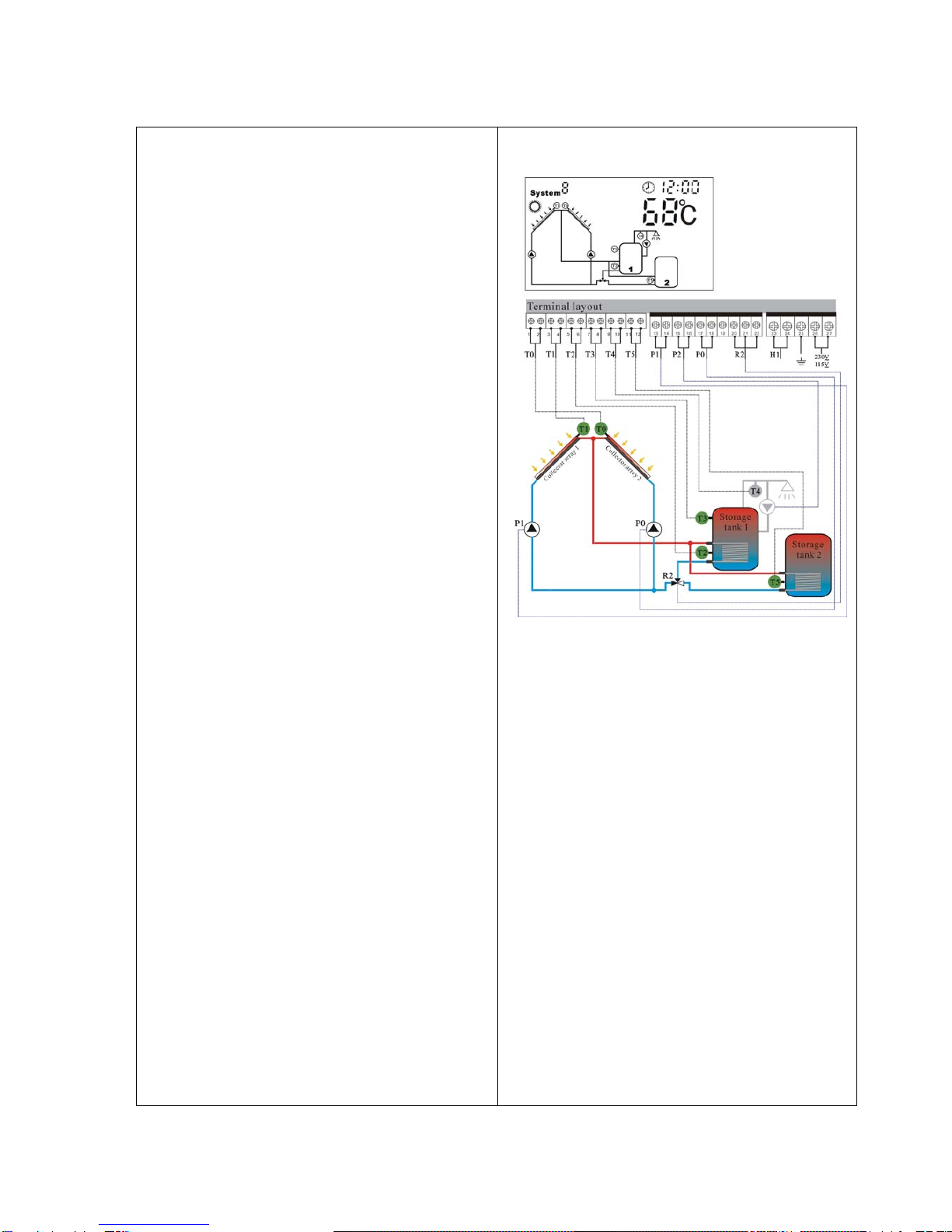
4.10 System 8
pump controlled 2 collector arrays( east/west
roof) – 2 storage tanks – 2 pumps – 1 valve
Description:
If the switch-on temperature difference between one
of the two tanks (T2, T5) and collector array1 (T1)
and collector array 2 (T0) is exceeded, then the
switching valve (R2) switches the relevant storage
tank (T2, or T5) into the solar circuit. If the switch-on
temperature difference between the storage tanks
(T2, T5) and one of the collector arrays (T1, T0) is
reached, then either solar circuit pump P1 for
collector array1 ( T1) , or solar circuit pump P0 for
collector array( T0) is switched on, depending on
where the temperature difference occurs. If the
switch-on temperature difference is reached for both
collector arrays (T1, T0), then both pumps (P1, P0)
are switched on. The switching valve (R2) controls
the loading of the storage tank (T2, t5) according to
the priority switching. The pumps ( P1, P0) switch
off independently of each other, when either the
relevant switch-off temperature for one or both of the
collector arrays ( T1, T0) with regard to the storage
tanks ( T3 or T4) falls below the threshold, or the
maximum storage temperature is reached.
T1: Temperature sensor for collector 1
T0: Temperature sensor for collector 2
T2: Temperature sensor in the bottom part of tank 1
T5: Temperature sensor in the bottom part of tank 2
P1: Solar circuit pump 1
P0: Solar circuit pimp 2
R2: 3-way switching valve 1 ( Ports 20,21 are shut off,
Ports 20,22 are turned on )
Note:
•When no voltage is on the system, the switching
valve ( R2) must be set to collector array 1( T1)
Default priority tank is tank 1( T1)
System 8 display
Shuangri Electron Co.,Ltd
http//www.shuangri.com

4.11 On/off of temperature difference controlling function
Functional description:
Solar circuit pump P1 is triggered by temperature difference function, so long as the preset temperature
difference between collector and tank is reached, solar pump is switched on.
When there are two tanks or two collector arrays, controller will compare the temperature between one tank
and one collector, one extra number indicates the correspondingly tank or collector.
For example: when we set the switch-on temperature difference is 8 oC, the switch-off temperature difference
is 4oC, and the temperature in bottom part of tank is 20oC, in this case, when the collector temperature
reaches 28oC, pump is triggered, when collector temperature falls below 24oC, pump stops.
Important information: the switch-on temperature difference 8oC and the switch-off temperature 4oC are
standard system setting according to many years’ experiences. Only in special application cases it is possible
to change (e.g. far distance heat transferring), switch-on and switch-off temperature difference are alternating
set. To avoid mistake the minimum difference between two temperature differences (∆Ton - ∆Toff ) is set as
2oC.
Setup steps:
►: Press “Temperature difference” button, switch-on delta T
setting area blinks.
Shuangri Electron Co.,Ltd
http//www.shuangri.com
►: Press “▲”“▼” button to adjust switch-on temperature
difference, adjustable range: (OFF + 2oC) ~ 20oC, default valve is
8oC.
►Press “ Temperature difference” button again, switch –off delta
T blinks
►: Press “▲”“▼” button to adjust switch-off temperature
difference, adjustable range: 0oC ~ ( On-2oC), default valve is 4oC.
After 6 seconds, controller confirms the setting.
4.12 Maximum tank temperature ( protection of tank at high temperature)
Functional description:
To avoid the temperature in tank is too high; controller will start its maximal tank temperature protection
function. Controller checks the temperature which getting from bottom part of tank and compares it with
turning-on and turning-off temperature of this function, when the temperature is higher than the turning-on
temperature, solar circuit pump is stopped, when the temperature is lower than tuning-off temperature, solar
circuit pump is triggered automatically. When the temperature of tank is higher than the maximum tank
temperature, even the condition of temperature difference circulation is reached, solar pump is still forbidden
to trigger.
Activate/deactivate this function:
►Press “Temperature set” button 2 times, the maximum tank
temperature setting area blinks, default setting is 90oC.
►Press“▲”“▼” button to adjust the maximum tank temperature
(adjustable range: 50oC – 95oC). After 6 seconds, controller
confirms the setting automatically.
►In the status of setting maximum tank temperature, press “OK”
button to deactivate this function, displays”----“

When signal of maximum tank temperature is displayed on screen, it indicates this function
activated.
4.13 Maximum collector temperature ( collector cooling function)
Functional description:
If the hot water in tank isn’t used, temperature in solar circulation will rise automatically after long time
sunshine, it is possible to avoid evaporating of heat transfer fluid by the restricted maximum collector
temperature. The heat loss through the collector will increase with the rising of temperature of heat transfer
liquid; this can be realized by the operation of solar circuit pump. . Through setting the maximal temperature
of collector can realize the cooling of collector.
Activate/deactivate this function:
►Press “Temperature set” button 3 times, the maximum collector
temperature setting area blinks, default setting is 115oC.
►Press“▲”“▼” button to adjust the maximum collector
temperature (adjustable range: 100oC –140oC), after 6 seconds,
controller confirms the setting automatically.
►In the status of setting collector maximum temperature, press
utton to deactivate this function, displays”-----“
Shuangri Electron Co.,Ltd
http//www.shuangri.com
“OK” b
When signal of maximum collector temperature is displayed on screen, it indicates this function
activated.
4.14 Collector emergency cut-off
Functional description:
When the temperature of collector exceeds 130oC, in order to protect the other components of solar circuit,
solar circuit pump is shut off compulsively. Restart conditions: the temperature of collector drops below 100oC
and tank temperature drops below the maximum tank temperature.
4.15 Protection of collector at low temperature
Functional description:
When the temperature of collector is below 15oC, even when the temperature difference exceeds switch-on
temperature difference, solar pump doesn’t work.
When the temperature of collector is above 20oC, solar pump starts to work.

4.16 Collector frost protection
Functional description:
In Winter when the temperature of collector is below the preset frost protection temperature (2-15oC),
electrical booster and solar pump starts work simultaneously. When the temperature of collector exceeds the
switch-off temperature of frost protection, controller stops solar pump and electrical booster and exits the
program.
Activate/deactivate this function:
►Press “temperature set” button 1 time, the frost protection
setting area blinks; default setting of 2oC is displayed.
►Press“▲”“▼” button to adjust the switch-on temperature of
frost protection, (adjustable range: 0oC –15oC), after 6 seconds,
controller confirms the setting automatically.
►In the status of setting frost protection temperature, press
“OK” button to deactivate this function, display”-----“.
When the signal displays on screen, it indicates frost protection function is activated.
4.17 Temperature-controlled hot water circuit pump
Functional description:
Solar system can provide temperature-controlled the hot water circulation function, this function needs a extra
hot water circulation pump ( P2) and a sensor (T4), which is positioned on the return pipe of hot water . When
the temperature signal of sensor T4 is less than the preset turning on temperature, the hot water circulation
pump (P2) triggers and works till the temperature exceeds the turning off temperature.
The default turning on temperature is 39oC; default turning off temperature is 45oC.
Activate/deactivate this function:
►Press “Temperature set” button 4 times, the hot water circulation
temperature setting area blinks, default setting is “OFF” mode,
“----”displays.
►Press “OK” button to activate this function.
►Press“▲”“▼” button to adjust the temperature of circulation
pump, (adjustable range: 20oC –50oC), after 6 seconds, controller
confirms the setting automatically.
►In the status of setting the temperature for circulation pump, press “OK” button to deactivate this function
Note: the position of the sensor T4 should be minimum 1.5m far from tank, so that avoid the measuring
error.
Shuangri Electron Co.,Ltd
http//www.shuangri.com

4.18 Time-controlled hot water circuit pump
Function description:
Solar system can provide time-controlled hot water circulation function, this function needs a extra circulation
pump (P2), this pump can be triggered by preset time. Within the preset time section pump operates for three
minutes, and then stops for 15 minutes, same process continues so. Three time sections can be set within
one day.
Setup steps:
►Press “ Timing Cyc” button, timing setting area blinks, to set
the start time of circulation.
►Press “▲”“▼” button to adjust hour
Shuangri Electron Co.,Ltd
http//www.shuangri.com
►Press “←”、“→” transfer button to minute area
►Press “▲”“▼” button to adjust minute
►Press “ Timing Cyc” button again to set the end time of
circulation
►Press “▲”“▼” button to adjust hour
►Press “←”、“→” transfer button to minute area
►Press “▲”“▼” button to adjust minute
•After 6 seconds, controller confirms setting automatically
•Doing like above steps. Within one day, three time sections can be set ( 1-3 displays on screen)
•If you want to shut off one timing circulation, then you set the turning on time and turning off time same
value ( for example, deactivate the function in the second time section, then you can set turning on/off time
is 10:00 ~ 10:00)
•Controller has memory function, the setting is remembered, don’t need to set everyday.
•The setting can be checked by pressing “Timing Cyc” button after setting.
Manual operation:
Press “ Timing Cyc” button for 3 seconds, the hot water circuit pump is triggered。If the time of this operation
is happened at the preset time section, it works as normal situation, namely works for 3 minutes, then stops
for 15 minutes, same process continues. If the time of this operation is not within the preset time section, it
works for 3 minutes, and then it stops automatically.
At the status that hot water circuit pump is working, press “ Timing Cyc” again to stop pump immediately.
4.19 Temperature controlled auxiliary heating at preset time sections
Functional description:
Solar system can be combined with electrical booster or gas, oil boiler, controller can achieve automatically
temperature and timing controlled heating, during the preset time sections electrical booster starts working
when the temperature (T3) of top part of tank is below the preset turning on temperature, when T3 exceeds
the preset turning off temperature, electrical booster stops heating.

When it is outside of the preset time section, electrical booster doesn’t work even when the tank temperature
reaches the turning –on temperature of electrical heating.
Setup steps:
►Press “Timing heating” button, timing area blinks on display, you can set turning on time and temperature of
electrical heating now,
►Press “▲”“▼” button to set hour,
►Press“←”、“→” button to shift to minute setting,
►Press “▲”“▼” to set minute.
►Press “←”、“→”again to shift to temperature area,
►Press “▲”“▼” to set turning on temperature of electrical
heating.
►Press “Timing heating” button again, you can set turning off
time and temperature of electrical heating
►press “▲”“▼” button to set hour,
►press“←”、“→” button to shift to minute setting,
►press “▲”“▼” to set minute.
►Press “←”、“→”again to shift to temperature setting,
►Press “▲”“▼” to set turning off temperature of electrical heating.
•6 seconds later controller confirms the settings
•Doing like above described steps, three timing sections can be set.( 1-3 displays)
•Default setting:
¾First heating time section: 4:00 turning on, 5:00 turning off
¾Second heating time section: not working, setting is 10:00 ~10:00
Shuangri Electron Co.,Ltd
http//www.shuangri.com
¾Third heating time section: 17:00 turning on, 22:00 turning off
¾Default turning on temperature of electrical booster is 50oC, turning off temperature is 55oC.
•If you want to shut off one timing heating, then you set the turning on time and turning off time same value
( for example, the second time section no this function, then you can set turning on/off time is 10:00 ~ 10:00)
•Controller has memory function, your setting is remembered, and you don’t need to set everyday.
•The setting can be checked by pressing “Timing heating” button.
Manual operation:
►Press “Timing heating” button for three seconds, electrical booster is triggered immediately, the
corresponding signal is lighted,
►Press “timing heating” button again, electrical booster switches off immediately.
Note: when no temperature sensor (T3) is installed in the top part of tank or T3 is damaged, controller
will take the signal from bottom temperature sensor ( T2) automatically and thereof control auxiliary
heating function.
When this signal displays on screen, it indicates the function activated.

4.20 Holiday function
Function description:
This function activates nightly storage tank back cooling and prevents high thermal loads of the solar system
due to completely heated storage tank. The function is activated when the collector temperature falls 8K
below the storage tank temperature at night between 10 pm and 6 am,.
Activate this function if:
•You intend to be absent for an extended period ( holiday)
•No hot water is required for an extended period.
The function is deactivated when the temperature in lower section
of storage tank falls down to 35oC.
Activating/deactivating the function
►Press “Holiday” button for 3 seconds, “Hd” blinks on display
screen, it indicates the function is active
►Press “Holiday” button for 3 seconds again, “Hd” hides, the function is deactivated.
Note:
•In the case of muti-storage tank systems, only storage tank 1 is used for storage tank back cooling.
•This function is only activated when you are not at home for long time, when you come back, please make
sure to deactivate it.
4.21 Auxiliary function
Note: the following described functions need an extra output port R2 to control pump or
electromagnetic valve, when all outputs are occupied, the desired function can’t be activated.
a. Temperature difference controlling (△T2)
setup steps:
►Press “ OK” button for 3 seconds, systems blinks
►Press “ →” one time and chosen the symbol which displays on
screen, chosen R2 temperature difference controlled output.
►Press “OK” to confirm setting, or 6 seconds later controller
confirms setting automatically
This function allows through temperature difference (sensor T0
and T5) to control a output port R2, it is used to control additional space heating or circulation.
►Press “Temperature difference” button three times, “△T2 ON” displays on screen.
►Press “▲”“▼” button to adjust switch-on temperature difference, adjustable range: ( OFF+2oC) ~
20oC,default is 8oC.
►Press “Temperature difference” button again, “△T2 OFF” displays on screen.
►Press “▲”“▼” button to adjust switch-off temperature difference, adjustable range: 0oC ~ (ON-2oC),default
is 4oC.
6 seconds later, controller confirms setting automatically.
Shuangri Electron Co.,Ltd
http//www.shuangri.com
Table of contents
Popular Control System manuals by other brands


eqss
eqss OverWatch JLG 94RT Series Install manual

Colorbeam
Colorbeam CORLORAY DMX 50W user guide

VPG
VPG TruckWeigh Installation, Setup and Calibration Manual

Recalart Electronic
Recalart Electronic MultiFun instruction manual

CENTURION SYSTEMS
CENTURION SYSTEMS SupaHelix installation manual

FUTABA
FUTABA 6EXA instruction manual