BlueRange TRUCK550 User manual

Page 1
OPERATION MANUAL
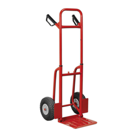
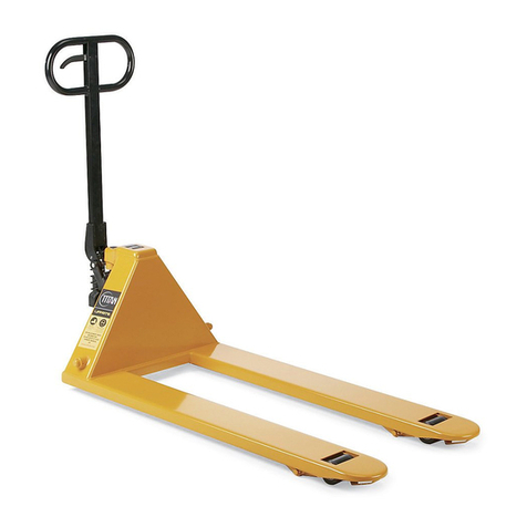
HYDRAULIC HAND PALLET TRUCK
IMPORTANT NOTICE:
Operator MUST read and understand the operating manual before using the
hand pallet truck.

Page 2

Page 3
HYDRAULIC HAND PALLET TRUCK
INSTRUCTIONS
This pallet truck is made of high quality steel and is designed for the horizontal lifting and
transport of loads on a pallet or standardized containers on a level, fixed base.
For your safety and correct operation, please carefully read this instruction before using it.
NOTE: All of the information contained herein is based on data available at the time of printing.
We reserve the right to modify our own products at any time and without notice.
1. GENERAL SPECIFICATIONS
Capacity kg 2500
Min. Fork Height H(mm) 80
Max. Fork Height H1(mm) 190-200
Max. Lifting Height mm 110
Fork Width B(mm) 550 or 685
Fork Length L(mm) 1200
Fork Size mm 150x55
Tandem Loading Wheel mm ED80x70
Steering Wheel mm 0180x50
Material of Wheel mm Nylon
Net Weight kg 73/75

Page 4
2. TO ATTACH DRAW-BAR TO PUMP UNIT (SUPPLIED UNASSEMBLED)
If your pallet truck has arrived unassembled, please follow the instructions to attach the Drawbar.
You will need following tools - a hammer, pliers, and spanner. Plus the following parts contained
in the enclosed bag:- Axle (A105), two cotter pins (A106) (Note one is pre fitted in the axle A105)
NOTE: The number of draw-bar and pump should be the same.
2.1 Insert the draw-bar onto the pump piston (A346), then
use a hammer to insert the axle with hole (A105) into the
hydraulic pump and draw-bar from the right to left. (See fig.
2 ).
2.2 Let control handle(A117) to the ‘LOWER’ position, then
pass the adjusting nut(A104), adjusting bolt(A103) and
chain(A102) through the hole of axle(A105) with your hand
(See fig. 3).
2.3 Press the draw-bar (A110, Al 10B) down, take away the
pin(#2) (See Fig. 1).
2.4 Let the control handle (A117) on ‘RAISE’ position, then
raise the lever plate (A315) with the pin (#2) and insert the
adjusting bolt(A103) into the front slot of lever plate (A315),
note to keep the adjusting nut (A104) on the under side of the
lever plate.
2.5 Use a hammer to tap another elastic pin (A106) into the
axle with hole (A105).
The draw-bar is now assembled to the pump.

Page 5
3. TO ADJUST RELEASE DEVICE
The control handle (A117) is located in at the top of the Draw Bar handle, it has three positions:
Lower position - RAISE the pallet forks when pumped.
Middle Position: DRIVE position – no movement of the forks when pumped.
Top Position: Lowers the pallet forks when handle is lifted, springs back to centre position when
released.
If however they have been changed, you can adjust according to following step:
3.1 If the forks elevate while pumping in the DRIVE position, turn the adjusting nut (A104) on the
adjusting bolt(A103) or screw(A318) clockwise until pumping action does not raise the forks and
the DRIVE position functions properly.
3.2 If the forks descend while pumping in the DRIVE position, turn the nut(A104) or screw(A318)
counter-clockwise until the forks do not lower.
3.3 If the forks do not descent when the control handle (A117) is in the LOWER position, turn the
nut(A104) or screw (A318) clockwise until raising the control handle(117) lowers the forks. Then
check the DRIVE position according to item 3.1 and 3.2 to be sure the nut (A104) and screw( A318)
is in the proper position.
3.4 if the forks do not elevate while pumping in the RAISE position, turn the nut (A104) or screw
(A318) counter-clockwise until the forks elevate while pumping in the RAISE position. Than check
the LOWER and DRIVE position according to item 3.1, 3.2 and item 3.3.
4. MAINTENANCE
The pallet truck is largely maintenance-free.
4.1 OIL
Please check the oil level every six months. The oil can be hydraulic oil: ISO VG32, its viscosity
should be 30cSt at 400 C, total volume is about 0.41t.
4.2 TO BLEED THE HYDRAULICS
The air may come trapped in the hydraulic oil because of transportation of the pump in a upturned
position. It can cause that the forks not to elevate while pumping in the RAISE position. The air can
been removed in the following way: hold the control handle (A117) on the LOWER position, then
move the draw-bar up and down for several times.
4.3 DAILY CHECK AND MAINTENANCE
Daily check of the pallet truck can limit wear as much as possible. Special attention should be paid
to the wheels, the axles, as thread, rags, etc, may jam the wheels. The forks should be unloaded and
lowered to the lowest position when the checks are completed.
4.4 LUBRICATION
All bearings and shafts are fitted with long-life grease at the factory. Grease points should be
checked and topped up if necessary every month with long-life grease, or when the bearings have
been overhauled.

Page 6
5 GUIDE TO SAFETY OPERATION
5.1 Operator should read all warning signs and instructions here and on the pallet truck
before using this truck.
5.2 Do not use on a slopping ground.
5.3 Do not operate a pallet truck unless you are familiar with it and have been trained or
authorized to do so.
5.4 Do not operate a pallet truck unless you have checked its condition. Giving special
attention to the wheels or rollers, the draw-bar unit, the fork unit, the lever plate, etc.
5.5 To pull the truck, always move the control handle into the drive position. This makes
the draw-bar easier to move and depressurizes the pump section of the hydraulics.
This preserves the hydraulic seals and the valve components. A long service life can be
expected.
5.6 Do not use the pallet truck to raise personnel.
5.7 Use the correct protective clothing, gloves and safety footwear.
5.8 Ensure people are at least 600mm clear of the truck when lowering the forks.
5.9 Do not load goods in an unstable manner as fig. 5/B .
5.10 Do not load over the maximum capacity.
5.11 Ensure vigilance is used when manoeuvring the pallet truck.

Page 7
6. TROUBLESHOOTING
NOTE: DO NOT ATTEMPT TO REPAIR THE PALLET TRUCK UNLESS YOU ARE TRAINED AND AUTHORIZED
TO DO SO.
No. Problem Cause Solution
1 The forks cannot be
raised up to their
maximum height.
• Not enough hydraulic oil in the
pump
• Top the unit up with hydraulic oil
2 The forks cannot be
lifted up
• No hydraulic oil.
• The oil has impurities in it.
• The nut (114) is too high, keep the
pumping valve open.
• The system has air in it.
• Fill the pump with oil.
• Change the oil.
• Adjust the nut(A104) or screw
(A318) (see 3.4)
• Bleed the air out (see 4.2)
3 The forks cannot be
lowered.
• The piston rod or pump body is
damaged as a result of overloading
or collision.
• The fork have been kept raised
for extended period, resulting in
rusting or contamination of the rod.
• The adjusting nut (114)is not in
correct Position
• Keep the forks in the lowest
position when not using and
keep the rod lubricated.
• Adjust the nut (A104) or screw
(A318) (see 3.3)
4 Leaks • Sealing parts worn or damaged.
• Pump casing cracked or rod is worn
• Replace with the new one.
• Replace with the new one.
5 The fork descends
without the lever
being in the RELEASE
position.
• The oil has impurities in it which
prevents the valve sealing.
• Part(s) of the hydraulic system is/
are cracked or worn.
• Air in the hydraulic oil.
• Sealing parts worn or damaged.
• The adjusting nut (A104) or screw
(A318) is not in the correct position.
• Replace with new oil.
• Inspect and replace the worn
parts.
• Bleed the air out. (See 4.2)
• Replace with the new one.
• Adjust the nut (A104) or screw
(A318). (See 3.2)

Page 8
EC DECLARATION OF CONFORMITY
Hand Pallet Truk Type: TRUCK550
TRUCK680
Date of Manufacture:
Is in Conformity with the following requirements:
Directives:
• 2006/42/CE
• 2006/95/CE
• 2004/108/CE
Manufacturer or his authorised representative in Community:
BLUERANGE
PO BOX 29
BOOTLE
MERSEYSIDE L20 1EJ
Date: January 2024
Authorised signatory:
For and on behalf of BLUERANGE
BLUERANGE
76 REGENT ROAD email: sales@bluerangetools.com
BOOTLE phone: 0151 955 4726
MERSEYSIDE L20 1BL
Version 2 : Jan2024
This manual suits for next models
1
Table of contents
