Blue Sky Energy - Solar Boost 1524iX
1
TABLE OF CONTENTS
IMPORTANT SAFETY INSTRUCTIONS................................................................................................................................ 2
PRODUCT DESCRIPTION...................................................................................................................................................... 3
Features Omitted in the Solar Boost 1524i ............................................................................................................ 3
Part Numbers and Options..................................................................................................................................... 3
OPERATION ......................................................................................................................................................................... 3
Charge Status Indicator.......................................................................................................................................... 3
Auxiliary Output Indicator ....................................................................................................................................... 3
Optional Remote Displays...................................................................................................................................... 3
Three Stage Charge Control .................................................................................................................................. 3
Bulk Charge ................................................................................................................................... 3
Acceptance Charge........................................................................................................................ 4
Float Charge .................................................................................................................................. ..4
Two Stage Charge Control..................................................................................................................................... 4
Equalization............................................................................................................................................................ 4
Current Limit........................................................................................................................................................... 4
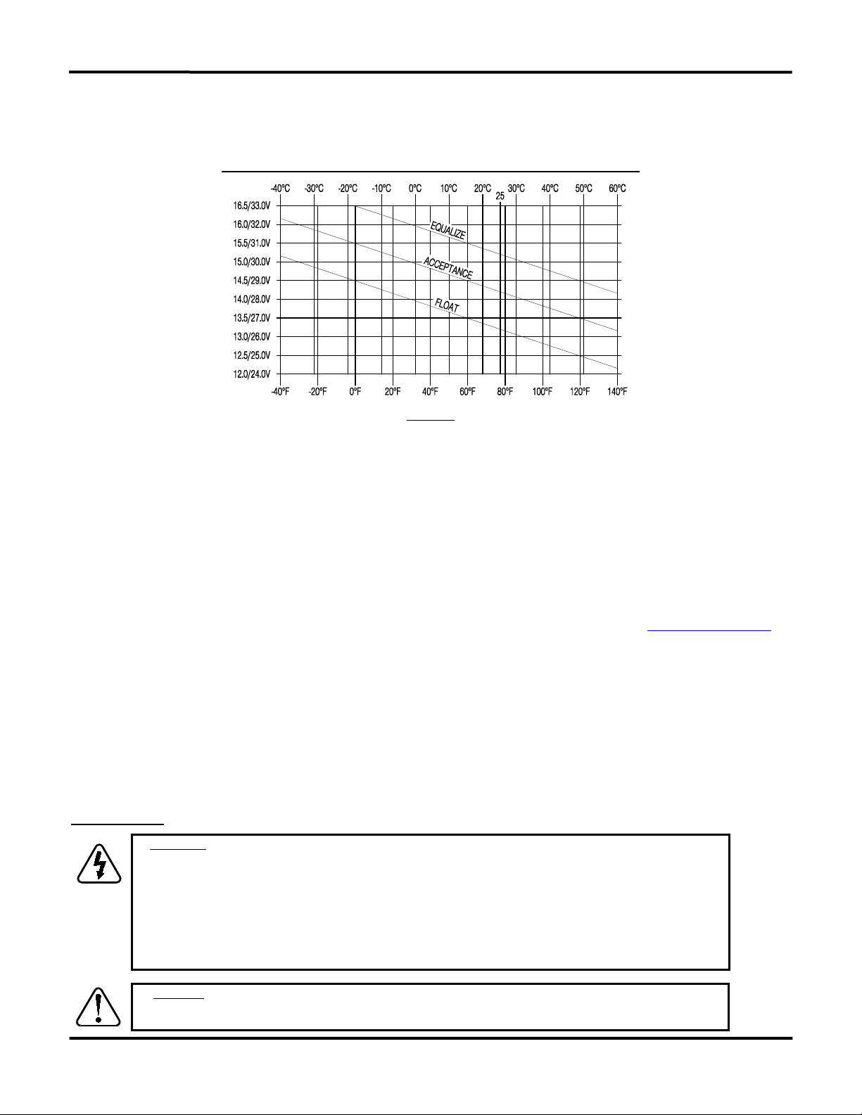
Optional Temperature Compensation .................................................................................................................... 5
Maximum Setpoint Voltage Limit............................................................................................................................ 5
Maximum Power Point Tracking (MPPT) ............................................................................................................... 5
Panel Temperature and Output Power................................................................................................................... 5
Multiple Charge Controllers On The IPN Network.................................................................................................. 5
INSTALLATION....................................................................................................................................................................... 5
Electrostatic Handling Precautions......................................................................................................................... 6
Battery and PV Voltage.......................................................................................................................................... 6
Selecting PV Modules ............................................................................................................................................ 6
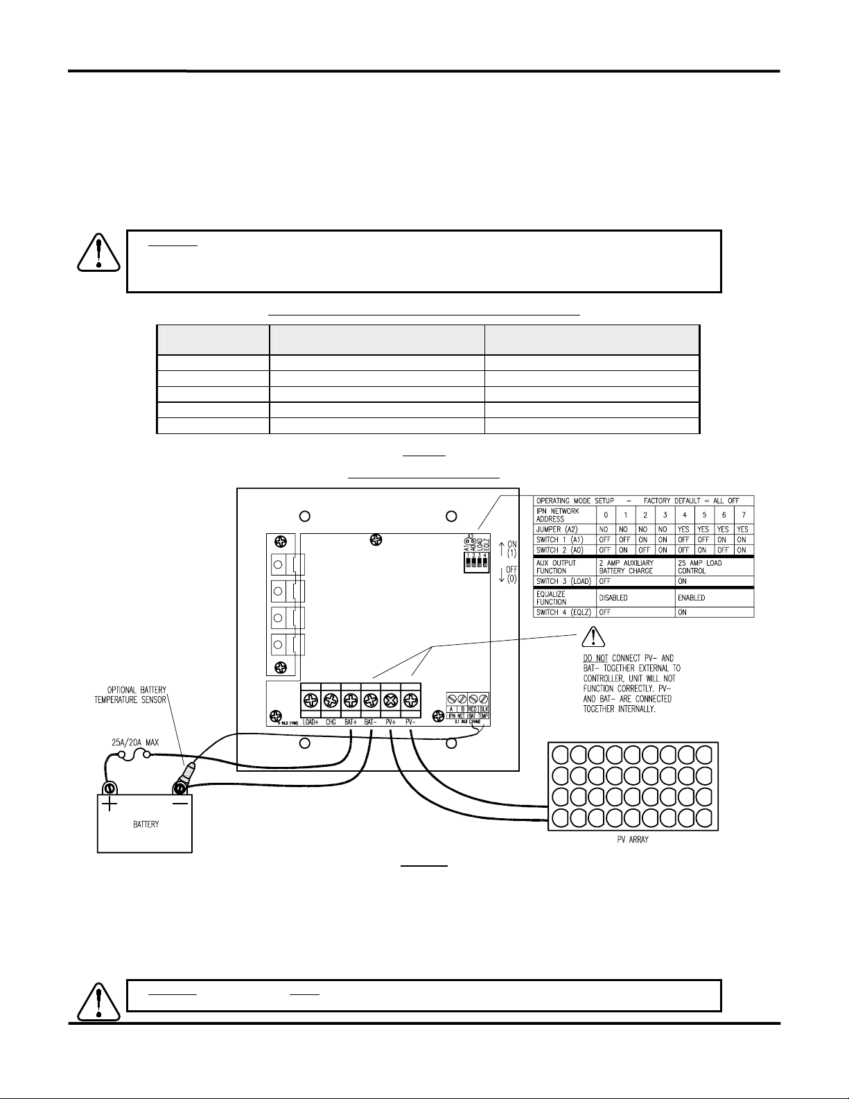
As Shipped Factory Default Settings...................................................................................................................... 6
Equalize Enable ..................................................................................................................................................... 6
Battery Temperature Sensor.................................................................................................................................. 6
Battery and PV Wiring............................................................................................................................................ 7
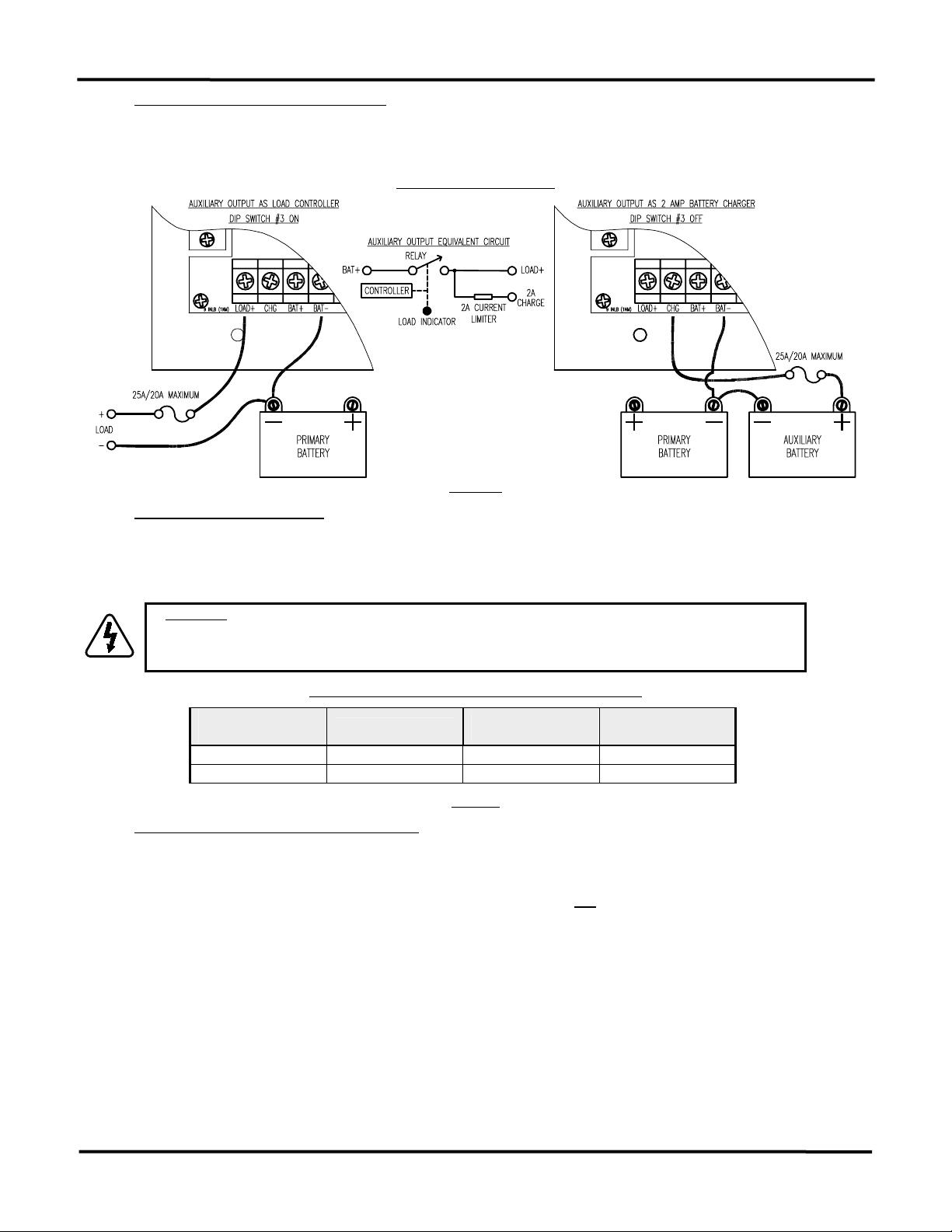
Auxiliary Output....................................................................................................................................................... 7
Auxiliary Battery Charge ................................................................................................................ 8
Load Controller............................................................................................................................... 8
Dusk-to-Dawn Lighting Control ...................................................................................................... 8
Installing a Multi-Controller System........................................................................................................................ 8
IPN Network Address..................................................................................................................... 9
Mounting................................................................................................................................................................. 9
TROUBLESHOOTING GUIDE................................................................................................................................................10
SPECIFICATIONS...................................................................................................................................................................11
ONE YEAR LIMITED WARRANTY.........................................................................................................................................11
TABLES AND FIGURES
Table 1 Charge Status Indicator ................................................................................................................. 3
Table 2 Maximum Conductor Length - 3% Voltage Drop..............................................................................7
Figure 1 Front Panel Indicators.................................................................................................................... 4
Figure 2 Factory Charge Voltage Setpoint -vs.- Battery Temperature......................................................... 5
Figure 3 Setup and Wiring Diagram............................................................................................................. 7
Figure 4 Auxiliary Output Wiring................................................................................................................... 8
Figure 5 IPN Network Wiring........................................................................................................................ 9
Figure 6 Detailed Dimensional Drawing....................................................................................................... 9