BlueSpot 07932 User manual
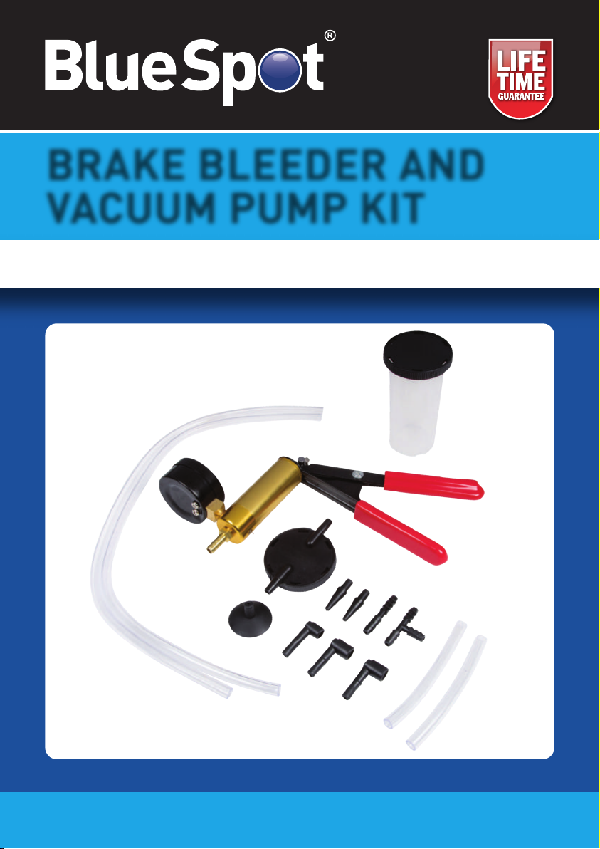
BRAKE BLEEDER AND
VACUUM PUMP KIT
User Manual
07932

01
Thank you for purchasing a BlueSpot product, you can find further information
on our range at www.BlueSpot.uk.com. Please ensure that you are using the
product correctly and that all guidance and cautions are followed in accordance
with the instructions. Please retain these instructions for future reference.
General Information
Please make sure that you read these instructions carefully in order to avoid injury when
using the tool. Follow all health and safety rules and regulations. If in doubt and available
please contact a more knowledgeable source.
DO NOT use if damaged.
• If the tool is damaged do not use as this may cause damage to property or injury.
• As with all vehicle testing and maintenance please use appropriate fixings such as axel
stands or wheel chocks.
• ALWAYS make sure the transmission is in park, wheels are blocked and the parking
brake is ON.
• ALWAYSs dress appropriately and wear the correct eye protection.
• ALWAYS keep a dry chemical fire extinguisher nearby.
• ALWAYS operate the vehicle in a well-ventilated area.
• Take great care around HOT or MOVING components.
• NEVER smoke around fuel components or the battery.
• NEVER disconnect any electrical connection with the ignition switch ON unless you are
instructed to do so.
• Avoid touching the electrical connector pins.
• DO NOT allow extension cords for power tools to lie on, near or across any vehicle
electrical wiring.
• Maintain the tool in good and clean condition for best and safest performance.
• Keep the work area clean, uncluttered and ensure there is adequate lighting.
• Maintain correct balance and footing. Ensure the floor is not slippery and wear non-slip
shoes.
• Keep children and unauthorised persons away from the work area.
Refer to vehicle manual and contact manufacturer if unsure.These instructions are
intended as a guide only.
Safe use
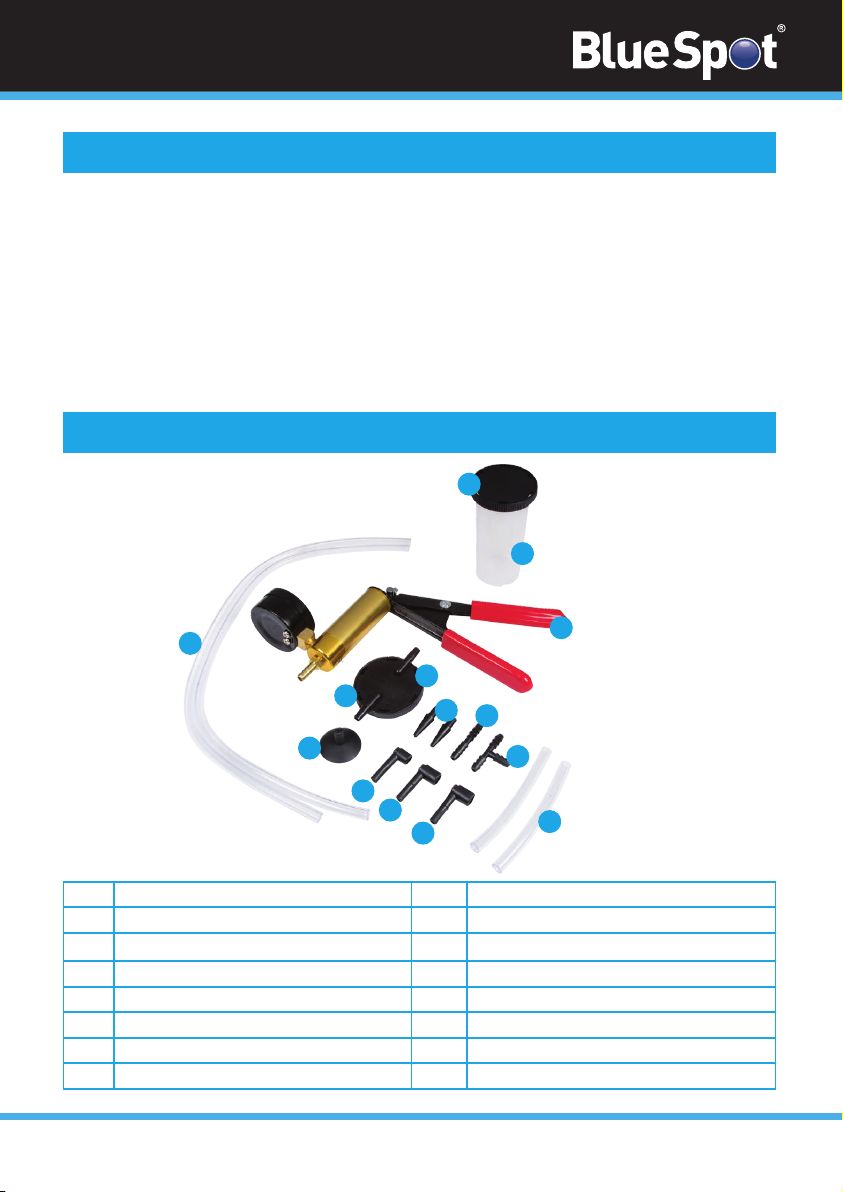
1
2a
2b
3
4
5
6
7
8
9a
9b
9c
10
11
Vacuum Pump with Gauge
Suction Lid
Transport Lid
Cup
2 Long Vacuum Hoses
2 Short Vacuum Hoses
Tapered Hose Adapter
“T” Hose Connecter
Straight Hose Connecter
Brake Bleed Screw Adapter A
Brake Bleed Screw Adapter B
Brake Bleed Screw Adapter C
Universal Cup Adapter
Cup O-Ring
Part Description Part Description
02
The BlueSpot Brake Bleeder and Vacuum Pump Kit is a multi-use testing tool for fuel,
transmission, ignition and emissions systems. Manufactured from high-quality material it
features a steel handle with rubberised coating for increased comfort and one-handed pump
action.
The set is ideal for removal of air in brake fluid lines by removing the air-filled fluid under a
vacuum. It is suitable for all vehicle types. The replaceable O-ring cylinder gasket, rubber
piston ring and valves ensure there is always an airtight fit. The easy-read dial displays
positive 0-760mmHg/0-30inHg, easy read dial and also up to negative 635mm Hg.
Introduction and Specification
Parts Diagram
1
2b
3
4
2a
10
5
11
6
9c
9b
9a
8
7
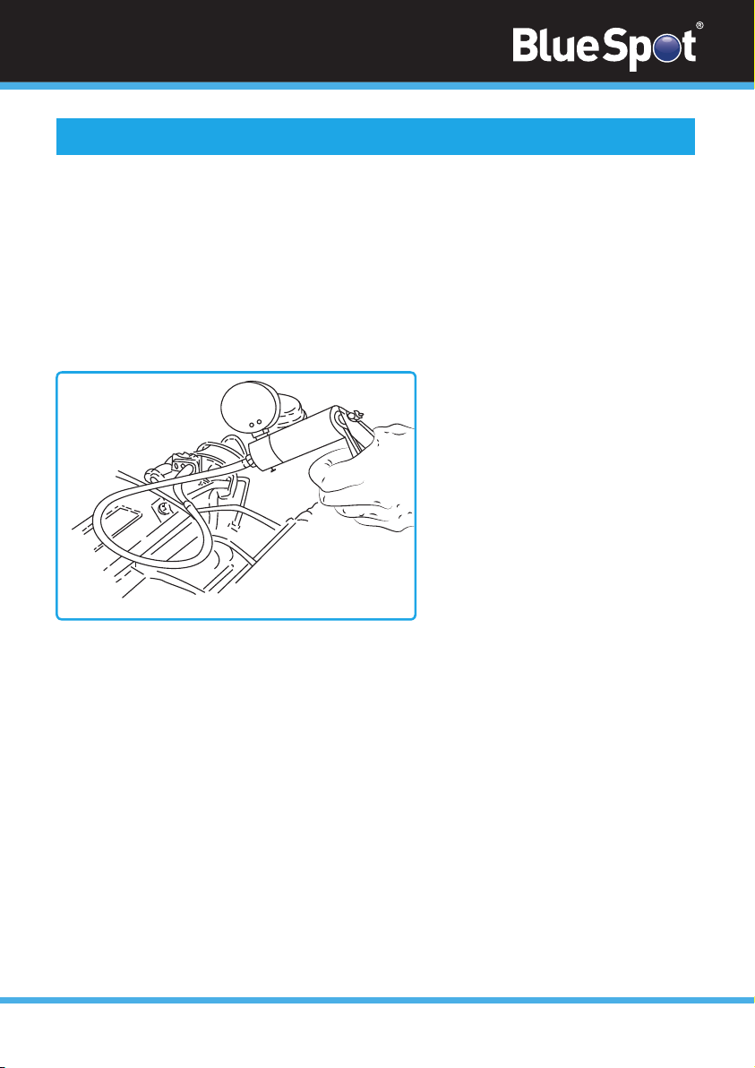
fig. 1
03
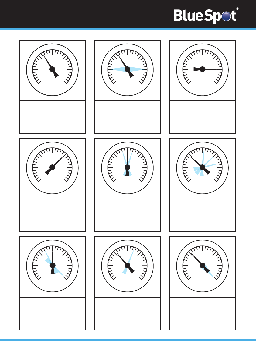
Analysing Engine Mechanical Condition via Manifold Readings
The readings shown below are examples of what you may observe.The action of the needle
is more important than the actual reading. Different engine types will run different manifold
vacuum pressures, depending on camshaft profile, valve overlap, timing etc. so an exact
vacuum reading cannot be specified.The main criteria is that the needle reading is between
16 to 21inHg and is steady.
Please consider when assessing manifold vacuum readings that the manifold vacuum is also
affected by altitude and it will drop approximately 1inHg for every 1000 feet above sea level.
Operation
Basic Diagnostic Test
1. Run the engine until the normal operating temperature is reached.
2. Switch the engine off.
3. Connect the Vacuum Pump with Gauge to a port directly on the manifold (figure 1)
or on the carburettor/throttle body below the throttle butterfly.
4. Start and run the vehicle engine at idle.
5. Observe the reading on the gauge.
6. Refer to the following diagrams to indicate readings and their possible meanings
and causes.
30
25
20
15
10
5
0
in Hg
76
70
60
10
20
30
50
40
30
25
20
15
10
5
0
in Hg
76
70
60
10
20
30
50
40
30
25
20
15
10
5
0
in Hg
76
70
60
10
20
30
50
40
30
25
20
15
10
5
0
in Hg
76
70
60
10
20
30
50
40
30
25
20
15
10
5
0
in Hg
76
70
60
10
20
30
50
40
30
25
20
15
10
5
0
in Hg
76
70
60
10
20
30
50
40
30
25
20
15
10
5
0
in Hg
76
70
60
10
20
30
50
40
30
25
20
15
10
5
0
in Hg
76
70
60
10
20
30
50
40
1 2 3
READING: 16-21 inHg with
needle steady.
CAUSE: Normal.
READING: Extremely low but
steady.
CAUSE: Leaking intake manifold
system, faulty manifold gasket,
carburettor base gasket, split
vacuum hose, EGR valve seized.
READING: When the throttle is
suddenly opened then released
the needle should drop to below
5inHg then bounce up to approx.
25inHg settling back to original
reading. CAUSE: Normal.
4 5 6
READING: Low but steady.
CAUSE: Pulled back ignition
timing. Confirm using the timing
light and reset to the
manufacturer’s specification.
READING: Regular fluctuation
between normal and low
readings. CAUSE: Blown head
gasket between two adjacent
cylinders. Carry out a cylinder
leakage test.
READING: Slightly low and
fluctuating slowly.
CAUSE: Over lean or rich
mixture. Check manufacturer’s
specifications and reset.
7 8 9
READING: Slightly lower
reading than a normal engine
including when the throttle is
suddenly opened then released.
CAUSE: Worn piston rings.
Carry out compression test.
READING: Normal when started
but drops rapidly when revs are
held at 3000rpm.
CAUSE: Restriction in the
exhaust system.
READING: Regular drop
between normal and low reading.
CAUSE: Burnt valve.
30
25
20
15
10
5
0
in Hg
76
70
60
10
20
30
50
40
30
25
20
15
10
5
0
in Hg
76
70
60
10
20
30
50
40
04
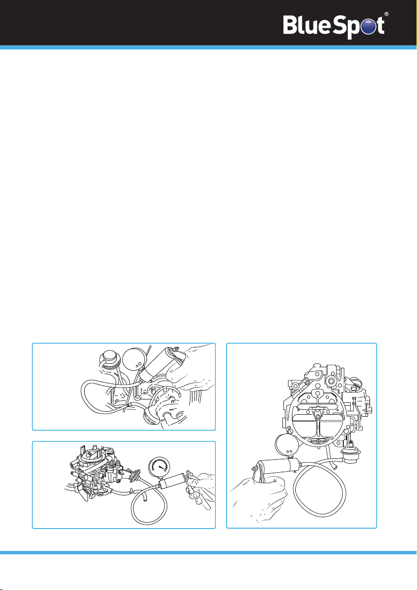
fig. 2
fig. 3
fig. 4
0
10
10
20
30
40
50
60
70
10
5
0
0
0
15
20
25
30
05
Ignition System Vacuum Advance
On standard points systems and some electronic ignition systems, there are two types of advanced
methods used, both of which function correctly to obtain maximum performance and fuel
economy.These are the mechanical or centrifugal method and the vacuum advance method.
Mechanical or Centrifugal Method
This method operates by the use of weights located in the base of the distributor.The weights
move outwards advancing ignition timing as engine RPM increases. Firstly remove the vacuum
advance line to disable the system.Then with the timing light connected, run the engine RPM up
checking that the timing advances in accordance with the manufacturer’s specification.
Vacuum Advance Method
This method senses engine load via the manifold vacuum. A vacuum diaphragm is mounted onto
the distributor and connected to a rotating internal base plate which advances or pulls back
timing as required to suit varying engine loads. For correct operation, again with the timing light
connected raise the engine RPM and check the timing advance against the manufacturer’s
specifications. If the vacuum advance is not operating, remove the vacuum line from the
distributor advance mechanism. Connect the vacuum tester (figure 2) and create a 5-10 inHg
vacuum, monitoring the timing at the same time. If a timing advance is noted this confirms that
the vacuum diaphragm and mechanical links are in order and that the fault is a vacuum supply.To
confirm this, connect the vacuum tester to the vacuum supply line and check the gauge reading.
No vacuum should be noted at idle but when the engine RPM is increased a vacuum increase
should be observed. If this does not occur, trace the vacuum line back checking for restrictions
and breaks.

06
Fuel Systems
The vacuum tester can be used to review the condition of a mechanical fuel pump by
testing the vacuum that it is able to create.
1. Remove the suction line from the pump.
2. Connect the vacuum tester to the suction port of the pump.
3. Start and run the engine at idle.
4. The vacuum reading that should be observed will differ slightly on different makes and
models of vehicle. However, as a general rule, approximately 15inHG of vacuum should
be created.This should also be held for approximately 1 minute after the engine is shut
down.The fuel pump will require either an overhaul or replacement.
Carburettors
The BlueSpot Brake Bleeder and Vacuum Pump Kit allows you to accurately test different
types of vacuum control systems. Below are two examples of tests that can be carried out.
Choke Break Diaphragm
1. Run the engine until the normal operating temperature is reached.
2. Switch the engine off.
3. Disconnect the vacuum line to the diaphragm module.
4. Connect the vacuum tester (figure 3) and apply approximately 15inHG of vacuum and
wait 30 seconds.
5. Observing the gauge there should be no drop.
6. With the vacuum still applied ensure that the choke butterfly is pulled to fully open the
position.
Vacuum Operated Carburettor Secondary Barrel
1. Run the engine until the normal operating temperature is reached.
2. Switch the engine off.
3. Remove the vacuum line from the second diaphragm module.
4. Connect the vacuum tester (figure 4).
5. Hold the throttle and secondary air valve flaps open.
6. Operate the hand pump whilst observing the free and easy opening of the secondary
throttle butterfly.
Testing Fuel Injection Pressure Regulator
The multi-point fuel injection rail pressure must vary to suit changing engine loads and fuel
delivery requirements.To sense the varying loads this is done using a vacuum-operated
regulator which is connected to the engine manifold vacuum.

fig. 5 fig. 6
0
To test the fuel rail pressure
1. Attach a gauge to the rail.
2. The engine loads must then be created to vary engine manifold vacuum.
3. Remove and block off the vacuum supply line to the pressure regulator.
4. Connect and operate the vacuum pump (figure 5) to simulate vacuum pressures. Refer
to the manufacturer’s specifications. Note the variation in fuel pressure reading.
Testing Emission Control Exhaust Gas Recirculation Valves (EGR)
1. Start the engine. Run at idle until the normal operating temperature is reached.
2. Remove the vacuum line from the EGR valve and attach the vacuum tester kit
(figure 6).
3. Apply approximately 15inHG of vacuum by operating the hand pump.
The idle engine will become rough if the EGR valve is working correctly. If the idle engine
remains unchanged the valve is possibly seized in the closed position. If the vacuum is not
held, the diaphragm in the valve has failed.
Additional Vacuum Systems
Testing One-Way Valves
Many vacuum-operated circuits use in-line one-way valves to apply vacuum in one
direction only.
To test the function of the valve
1. Remove the valve from the circuit.
2. Attach the vacuum tester (figure 7) and apply vacuum by operating the pump.
3. In one direction the valve should hold vacuum and in the opposite direction, it
should not.
Testing Electrically Operated Vacuum Solenoids
Electrically operated vacuum solenoids are commonly used in control circuits for air
conditioning/ventilation systems, emission control systems, idle step up systems etc.
07

08
1. Locate the solenoid to be tested.
2. Remove the line that goes to the component being tested.
3. Connect the vacuum tester to the solenoid port (figure 8).
4. Start the engine.
5. With the system turned off there should be a zero gauge reading.
6. Turn the system to the ‘on’ position.
7. A gauge reading equal to the manifold vacuum should be observed. If no reading exists
remove the vacuum supply line and test for manifold vacuum.
If the vacuum does exist this indicates that the solenoid is faulty or is not receiving a
‘switch on’ voltage.You can use a multimeter to test this.
If no vacuum exists trace the supply line back to the vacuum source checking for kinks and
breaks.
Testing Thermal Vacuum Switches
There are many vacuum controlled circuits that must only operate when the engine reaches
the normal operating temperature.To do this you use the thermal switches that remain in
an ‘off’ position until a given temperature is reached.
To test this type of switch
1. Remove the vacuum supply line coming from the manifold to the switch and test for
manifold vacuum.
2. If this vacuum is correct refit the supply line to the thermal switch and remove the
opposing from the switch.
3. Attach the vacuum tester to the port (figure 9).
4. Start the engine.
5. With a cold engine, no reading should be noted.
6. When the engine reaches normal operating temperature a manifold vacuum reading
should be noted.
Testing Vacuum Operated Heater Taps
On newer vehicles, climate control ventilation systems are becoming more popular. Most of
these systems use vacuum operated taps to control the heating modes.The system on the
majority of makes and models use vacuum to turn the heater tap ‘on’.
To test these
1. Remove the supply line from the tap vacuum module.
2. Connect the vacuum tester (figure 10).
3. With the engine at normal operating temperature locate and feel the heater return hose.
4. With the heater tap in the ‘off’ position, this hose should be cold.
5. Open the tap by operating the vacuum pump.
6. The gauge reading must hold.
If the return hose begins to heat the tap is in working order. If the tap is faulty the hose
will not begin to heat.

09
Testing Vacuum Operated Remote Central Locking Systems
Some makes and models of vehicles use vacuum operated bellows mounted in each door to
centrally lock and unlock the vehicle doors.
These systems use either manifold vacuum stored in a reservoir for use when the engine is
not running or an electrically driven vacuum pump which operates when the doors are
locked or unlocked.
For either system, the vacuum tester is ideal for testing each individual door bellows.
1. Remove the door trims as required.
2. Remove the vacuum supply lines from the bellows.
3. Attach the vacuum tester (figure 11).
4. Operate the vacuum tester to apply vacuum to the bellows.
5. Wait 30 seconds.
6. No drop on the gauge should be noted.
7. If the bellows are in working order attach the vacuum supply line to the vacuum tester.
8. Operate the vacuum system to test for vacuum supply.
9. If the vacuum supply does not exist or is low trace back down the lines to the vacuum
supply. Look for kinks, restrictions or cracked lines. Repair any issues and test again.
Testing Automatic Transmission Vacuum Operated Modulator Valves
For the automatic transmission to detect engine loads and adjust shift points to suit,
automatic transmissions are normally equipped with a vacuum operated nodular valve.
The vacuum tester can be used to test both the modulation valve diaphragm is serviceable
and also to simulate varying engine loads so modulator pressure readings can be recorded.
Testing the Modulator Valve Diaphragm
1. Remove the vacuum supply line from the valve.
2. Attach the vacuum tester.
3. Operate the vacuum pump until approximately 15inHG is achieved.
4. Monitor the gauge for approximately 30 seconds.
5. No vacuum drop should be noted.
Checking Modulator Pressure Readings
1. Attach a pressure gauge to the appropriate port on the transmission.
2. Remove the vacuum supply line from the modulator.
3. Attach the vacuum tester (figure 12).
4. Start and run the engine.
5. Apply vacuum pressures.
6. Monitor readings and check these against the manufacturer’s specifications.
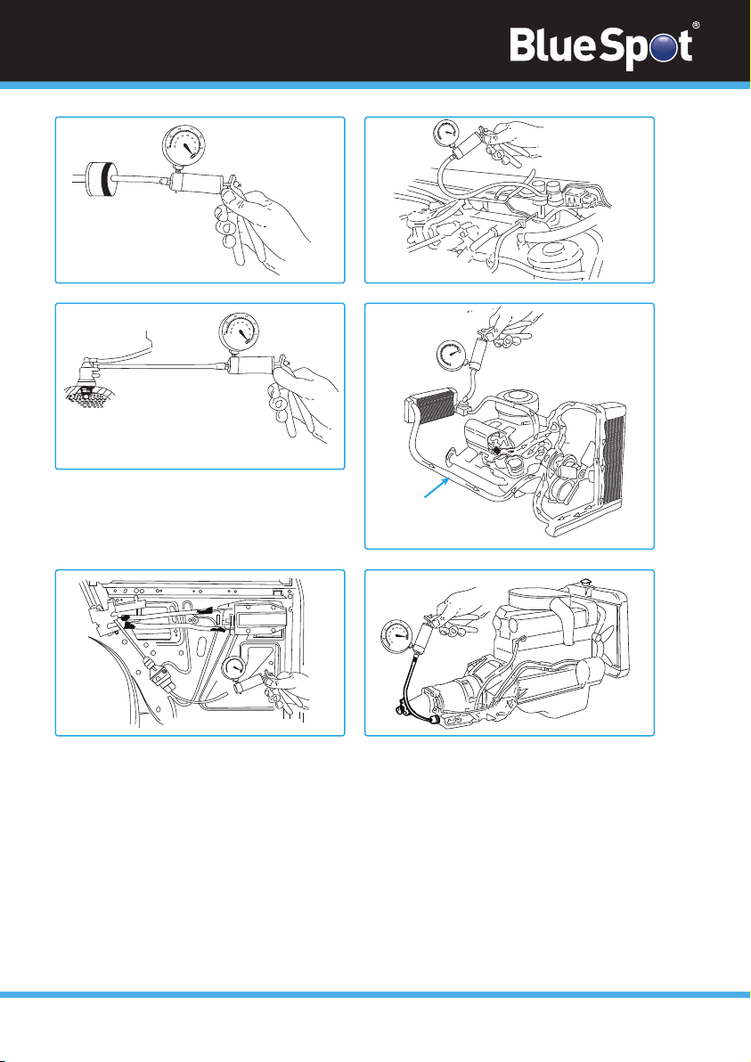
fig. 11 fig. 12
fig. 9
fig. 10
fig. 7 fig. 8
0
10
10
20
30
40
50
60
70
10
5
0
0
0
0
15
20
25
30
0
10
10
20
30
40
50
60
70
10
5
0
0
0
0
15
20
25
30
0
5
10
10
20
30
40
50
60
70
80
20
25
30
0
15
10
Braking Systems
Testing Brake Servo Diaphragm
1. Remove the vacuum supply line from the brake servo fitting.
2. Attach the vacuum tester to the vacuum supply port on servo (figure 13).
3. Create approximately 15 inHG by operating the pump.
4. Wait 30 seconds.
5. Check the gauge reading – there should be no vacuum drop observed.
If the vacuum drops this indicates the brake servo diaphragm is faulty. If faulty the servo
should be removed by an authorised repairer or replaced.
To manifold vaccum
Return Hose

11
Brake Bleeding – Assembly of Brake Bleeding Kit
1. Connect the vacuum pump to the brake bleeder reservoir. Refer to the assembly diagram
if you are unsure on how to do this (figure 14).
If this is not done correctly the brake fluid would be drawn into the vacuum pump.
Brake Bleeding
ALWAYS be aware of the brake fluid hazards before you begin bleeding the brakes. Refer
to the manufacturer’s instructions.
NEVER touch the vehicles brake pedal whilst bleeding the brakes.
ALWAYS refer to the vehicle manufacturers instructions for brake bleeding and wheel
sequence before beginning. If the vehicle manufacturer does not have specific instructions
please follow the instructions listed below.
1. Remove the cap from the vehicle’s master brake fluid reservoir.
2. Top up the fluid if it is not at its maximum.
3. Attach the appropriate bleeding size attachment to the bleed nipple on the brake calliper
of the first wheel. Refer to the vehicle manufacturers instructions for guidance the wheel
sequence. If you do not have this the first wheel is normally the furthest wheel from the
master brake fluid reservoir.
4. Operate the vacuum pump until approximately 21 inHG vacuum is created.
5. To reduce the possibility of seized or broken nipples when the brakes are next bled, apply
copper grease to the brake bleeding nipples.
6. Open the bleed nipple a quarter of a turn. Allow the brake fluid to be drawn until no air
bubbles are visible in the brake fluid in the clear hose.
7. Tighten the bleed nipple.
8. Remove the attachment from the brake nipple.
9. Repeat the process where necessary.
10. When the brake bleeding and/or fluid change is complete, test the brake pedal to ensure
the brakes are working before attempting to drive the vehicle on the road.
11. Test the vehicle for satisfactory performance of the braking system.
ALWAYS check the master brake fluid reservoir regularly. Ensure that the level does not
drop too low.Top up the brake fluid when necessary.
ALWAYS empty the brake bleeder container regularly. Never allow the container to overfill
as brake fluid will be drawn into the vacuum pump.
Clutch Bleeding Procedure
ALWAYS refer to the relevant vehicle manufacturers instructions for the clutch bleeding
procedure. If the vehicle manufacturer does not have the specific instructions on how to do
this, follow the same basic procedure as the brake bleeding instructions listed above.
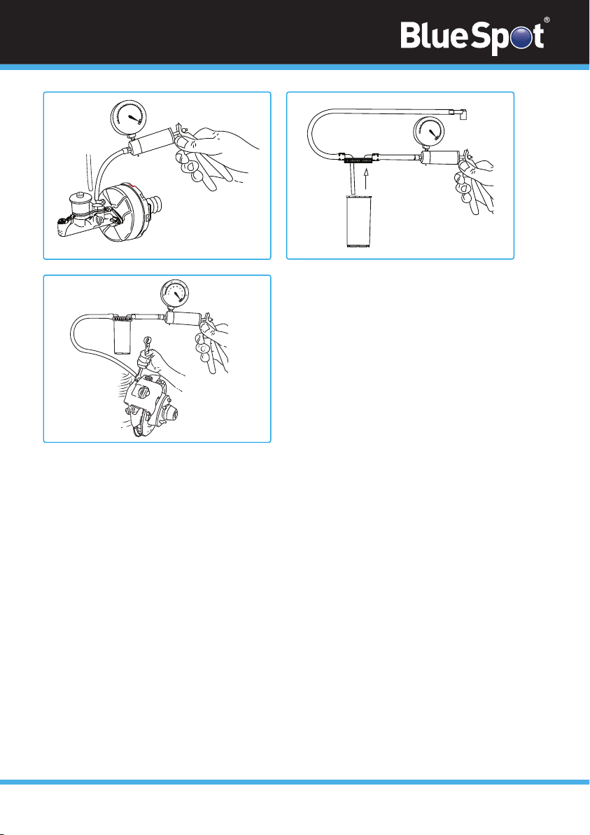
fig. 13 fig. 14
5
10
10
20
30
40
50
60
70
80
20
25
30
0
15
5
10
10
20
40
50
60
70
80
20
25
30
0
15
fig. 15
30
0
12
Maintenance of the Brake Bleeder and Vacuum Pump Kit
1. Before each use – Inspect the general condition of the Vacuum Pump. Check for broken
parts, damaged Hoses, loose connections and anything that could affect the safe
operation of the Vacuum Pump. Do not use equipment if damaged.
2. Cleaning – Use a clean dry cloth to clean the Vacuum Pump. Do not immerse the
Vacuum Pump in any liquid. Do not clean the Vacuum Pump with any cleaners or
solvents.
3. Storage – Dispose of excess fluid properly after each use. Contact your local waste
disposal authority for information on how to correctly dispose of fluids. Do not store
fluid in the Cup. Store the Vacuum Pump in a clean, dry area out of the reach of
children.

13
Notes
Contact
Find out more about the BlueSpot® Lifetime Guarantee at www.BlueSpot.uk.com
Tel: 0800 093 0115
Email: [email protected]
Orme Business Centre,
Greenacres Road,
Oldham,
OL4 3NT
ContactDistance to Spot Size
Recycle unwanted materials instead of disposing of them as waste. All tools, accessories and
packaging should be sorted, taken to a recycling centre and disposed of in a manner which is
compatible with the environment. When the product becomes completely unserviceable and
requires disposal, drain any fluids (if applicable) into approved containers and dispose
of the product and fluids according to local regulations.
Environmental Protection
Notes
ContactDistance to Spot Size
Notes
Table of contents
Popular Automobile Accessories manuals by other brands

BM PRO
BM PRO ASPero owner's manual

TigerTough
TigerTough T62213 installation guide

Silvercrest
Silvercrest SBTF 10 B2 operating instructions

Horn Tools
Horn Tools HUF L200M 15 installation manual

Maxxair
Maxxair SKYMAXX 97500i Installation instructions, Information and Operating guide

Air Lift
Air Lift 27691 instruction manual

Air Lift
Air Lift Ride Control 59554 quick start guide

Weather Guard
Weather Guard PowerSync installation guide

Air-Bus
Air-Bus CARK-9 installation guide

MRHANDSFREE
MRHANDSFREE Blue Multi user manual

FormFit
FormFit Tough Guard TG 7W07 installation instructions

4x4 TOUGH
4x4 TOUGH ROOF RACKS instruction manual


