Air-Bus CARK-9 User manual

IH - PS11721BMLAB01
09/2017
EN
DE
ES
FR
IT
NL
Car Kit
CARK-9
- Installation Guide
Profi-Kfz-Ausstattung CARK-9 Installationshandbuch
Kit de coche
CARK-9
- Guía de Instalación
Solution confort routier
CARK-9
- Manuel d’Installation
Kit vivavoce veicolare
CARK-9
- Manuale di Installazione
Car kit CARK-9 Installatiehandleiding
print.book Page 1 Jeudi, 28. septembre 2017 7:54 07

09/2017
IH - PS11721BMLAB01
Copyright
®
2015 - 2017 Airbus DS SLC. All rights reserved.
EN
DE
ES
FR
IT
NL
Version 3
HR8159AA
print.book Page 2 Jeudi, 28. septembre 2017 7:54 07

IH - PS11721BMLAB01
09/2017
1/8
Copyright
®
2015 - 2017 Airbus DS SLC. All rights reserved.
Car Kit CARK-9 - Installation Guide
EN
Introduction
This installation guide has been prepared to provide the basic information necessary to
install CARK-9. This guide is not intended to be definitive, because different types and
models of vehicles will require different installation work. The information given is for
general guidance only.
The terms of warranty demand that this car kit be installed by an experienced installer
and that only specified parts are used. An end-user should never attempt to install this
car kit without professional assistance as the installation requires special tools and
knowledge.
Please refer to the radio’s User Guide for instructions on the radio’s operation, care and
maintenance, including important safety information.
Note:
Read the warnings below before beginning the installation procedure.
WARNINGS
1. ENSURE THAT THE VEHICLE’S BATTERY IS DISCONNECTED BEFORE YOU
START THE INSTALLATION PROCEDURE, AND THAT IT REMAINS
DISCONNECTED DURING THE PROCEDURE.
2. DO NOT SMOKE OR USE OPEN FLAMES WHEN WORKING NEAR THE
VEHICLE’S FUEL SYSTEM.
3. ENSURE THAT THE VEHICLE’S ELECTRICAL CABLES, HYDRAULIC LINES,
FUEL LINES, AND SAFETY EQUIPMENT ARE NOT DAMAGED DURING
INSTALLATION.
4. ENSURE THAT NORMAL CONTROL AND OPERATION OF THE VEHICLE IS
NOT IMPAIRED BY THE INSTALLATION, PARTICULARLY THE BRAKES AND
STEERING. ENSURE THAT AIRBAG OPERATION IS NOT OBSTRUCTED.
5. ELECTRONIC AND OTHER SOPHISTICATED SYSTEMS (e.g. SPEED
CONTROL, ABS ANTI-LOCK BRAKE, FUEL INJECTION-, NAVIGATION-, AND
AIR-BAG SYSTEMS) ARE RELATIVELY IMMUNE TO MALFUNCTION CAUSED
BY NEARBY RADIO TRANSMISSIONS. HOWEVER, SHOULD YOU
EXPERIENCE FALSE OPERATION OF THESE SYSTEMS OR ARE IN ANY
DOUBT WHATSOEVER AS TO THEIR FUNCTIONALITY, PLEASE CONSULT
THE VEHICLE’S DEALER.
6. THE CAR KIT IS SUITABLE FOR USE ONLY IN VEHICLES WITH A 12 V
NEGATIVE GROUNDING. USE ON OTHER SUPPLY VOLTAGES OR
ALTERNATIVE POLARITY WILL DAMAGE THE EQUIPMENT.
7. THE RADIO SHOULD NOT BE LEFT SWITCHED ON FOR EXTENDED PERIODS
WITHOUT RUNNING THE VEHICLE’S ENGINE. FAILURE TO COMPLY COULD
DRAIN THE VEHICLE’S BATTERY.
8. SIDE CONNECTOR ACCESSORIES SHOULD BE REMOVED FROM THE
TERMINAL BEFORE THE TERMINAL CAN BE USED IN THE CARKIT
INSTALLATION.
print.book Page 1 Jeudi, 28. septembre 2017 7:54 07

2/8
09/2017
IH - PS11721BMLAB01
Copyright
®
2015 - 2017 Airbus DS SLC. All rights reserved.
EN
Car Kit CARK-9 - Installation Guide
Components of CARK-9
Fig. 1. Installation without the DTC-1 Adapter Cable
The CARK-9 includes the above parts. Please note that the items enclosed within broken
lines are not supplied with CARK-9.
print.book Page 2 Jeudi, 28. septembre 2017 7:54 07

IH - PS11721BMLAB01
09/2017
3/8
Copyright
®
2015 - 2017 Airbus DS SLC. All rights reserved.
Car Kit CARK-9 - Installation Guide
EN
Fig. 2. Installation using the DTC-1 Adapter Cable
Please note that all items shown above are included in CARK-9 except those enclosed
within broken lines.
*Two of these accessories can be connected simultaneously.
Warning
Side connector accessories should be removed from the terminal before the terminal
can be used in the car kit installation.
print.book Page 3 Jeudi, 28. septembre 2017 7:54 07

4/8
09/2017
IH - PS11721BMLAB01
Copyright
®
2015 - 2017 Airbus DS SLC. All rights reserved.
EN
Car Kit CARK-9 - Installation Guide
Component Parts
Advanced Active Holder MCR-4
The holder for the radio is attached to the vehicle’s interior in a convenient position using
the swivel mount HHS-14. The mounting is secured with a screw (included with HHS-14).
The screw recess is covered with the rubber plate.
The cable with the plug-in connector from MCR-4 connects to the
PHONE
socket in
HFU-2T. (The other cables from MCR-4 connects to the external TETRA and GPS
antennas.)
Swivel Mount HHS-14 and Mounting Plate MKU-1
HHS-14 is a swivel mount which allows for adjustable fixing. MKU-1 is a fixed position
mounting plate.
Advanced HF Unit HFU-2T
The handsfree unit HFU-2T is attached to the vehicle interior using the mounting plate
MKU-1. The mounting is secured with a screw (included with MKU-1).
Power Cable PCH-4J
The power cable connects to the
DC
socket in HFU-2Tand to the vehicle’spower supply.
See the ”Installation” section for more information.
HF Microphone MP-3
The HF microphone connects to the
MIC
socket in HFU-2T.
Push the plug to lock it firmly
in place
.
HF Speaker HFS-12
The HF speaker connects to the
SPEAKER
socket in HFU-2T.
Push the plug to lock it
firmly in place
.
Adapter Cable DTC-1
The DTC-1 adapter cable connects to the HFU-2T DATA/HANDSET socket. It provides
for the possibility of connecting to two out of three possible accessories: PTT-1, HSU-1T
and DLR-3T. It comprises specified sockets for DATA and HANDSET connection.
Note that if only one of these three accessories is used, it must be connected directly to
the HFU-2T without using the DTC-1!
External Push to Talk Key PTT-1
The external push to talk key is to be used during a one-way call. The key connects
directly to the HFU-2T DATA/HANDSET socket or to either socket in the DTC-1 Adapter
cable (please refer to DTC-1).
Note that the external push to talk key is not allowed to be installed to a vehicle control
device!
Data Adapter Cable DLR-3T (not supplied)
The data adapter cable enables RS232 data connection totheradio. The cableconnects
directly to the HFU-2T DATA/HANDSET socket or to the DTC-1 adapter cable DATA
socket (please refer to DTC-1). For more information, please refer to the user guide for
the data adapter cable.
External Mobile Antenna (not supplied)
An external TETRA-band antenna is recommended for the car kit. It connects to MCR-4.
External GPS Antenna (not supplied)
An external GPS-band antenna is recommended for the car kit. It connects to MCR-4.
print.book Page 4 Jeudi, 28. septembre 2017 7:54 07

IH - PS11721BMLAB01
09/2017
5/8
Copyright
®
2015 - 2017 Airbus DS SLC. All rights reserved.
Car Kit CARK-9 - Installation Guide
EN
Handset HSU-1T (not supplied)
Thehandset HSU-1Toffersmoreprivacy duringa call.Duringa one-waycall thePTT key
must be used. It connects to the
DATA/HANDSET
socket of HFU-2T or to the DTC-1
adapter cable HANDSET socket (please refer to DTC-1). For more information, please
refer to the user guide for the handset.
Installation
For an example of installation locations, please see the cover.
Note:
Ensure that the battery of the vehicle is disconnected before you start the
installation or start making changes to the installations, and that it remains disconnected
during the installation procedure.
The HFU-2T and the different parts are connected as mentioned in the ”Component
Parts” section.
There are some important aspects that require special attention in positioning car kit
accessories.
The location of the holder should be selected so that the radio's display is easily visible
and that the driver’s attention is not distracted. The location of the holder should allow the
driver to easily reach the keypad. Under no circumstances should the holder in any way
prevent the driver from controlling or operating the vehicle.
The HF microphone should be installed according to the directions in the separate
microphone installation guide. Ensure that the microphone is as close to the driver’s
mouth as possible, and attached to a surface that is mechanically quiet. The microphone
should be mounted at least 3 ft/1 m away from the handsfree unit speaker to avoid
acoustic feedback.
Ensure that the cables are routed as far away as possible from the vehicle’s electronic
systems. This is to prevent interference. Also, ensure that the cables are not subjected to
undue mechanical stress e.g. under seats or against sharp edges.
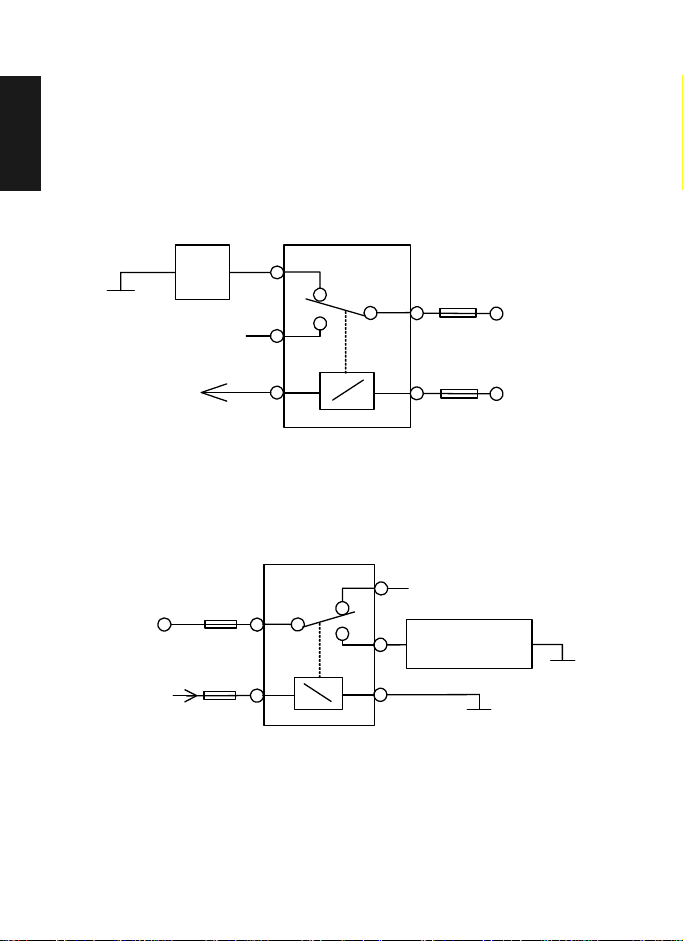
PCH-4J
Thecablesfrom PCH-4Jare colourcoded. Theyarelistedin thefollowingtablein column
A and each cable should be connected to the corresponding item listed in column B.
A B
Red cable (with 2 amp fuse) The + voltage on the vehicle’s power supply.
Black cable The negative GND connection.
Blue cable (with 1 amp fuse) The +12 V voltage controlled by the vehicle’s ignition
key. (See section ”Ignition Sense IGNS”.)
Yellow cable Used for car radio muting (XCRM) and is connected
to the car radio. The line goes down to 0 volts during
a call. See section ”Car Radio Muting CRM”.
Green cable (with 1 amp fuse) The motor antenna (AMC). The voltage in this output
is +12 V whenever the phone is on. See section
”Antenna Motor Control AMC”.
print.book Page 5 Jeudi, 28. septembre 2017 7:54 07

6/8
09/2017
IH - PS11721BMLAB01
Copyright
®
2015 - 2017 Airbus DS SLC. All rights reserved.
EN
Car Kit CARK-9 - Installation Guide
Ignition Sense IGNS
The ignition sense feature prevents your car kit from draining the car battery by executing
an auto power off 20 seconds after the ignition key has been turned off. The blue cable
from PCH-4J is used for the ignition sense feature. The use of ignition sense is
recommended to prevent accidental draining of the car’s battery. The cable is connected
via a 1-A fuse to a 12- V supply that is controlled by the ignition key. Do not connect it
directly to the high voltage sections of the ignition circuit.
Car Radio Muting CRM
The car kit offers a feature that can mute the car radio automatically during a
conversation. The following is the circuit diagram for CRM.
Another possibility is to use a special muting unit, which mutes the radio by connecting
load resistors to the speaker lines of the car radio.
Antenna Motor Control AMC
The antenna motor control may be used to turn different devices on and off. The
maximum output current is 200 mA; therefore, for example, a motorized antenna must be
controlled via a relay, see diagram below.
All installations should take into account any special requirements of the customer.
However, should the customer require an installation that is illegal or unsafe these facts
must be pointed out to the customer and a policy of non-compliance adopted.
GND CAR
RADIO 87A
87
85
30
86
Relay (12 V)
12 V d.c.
12 V d.c.
Supply for
car radio
Fuse 200 mA
(not supplied)
To XCRM line
(yellow wire)
GND
CONTROLLED
DEVICE e.g.
MOTOR ANTENNA
87A
87
85
30
86
Relay (12 V)
12 V d.c.
Supply
for
device
From AMC line
(green wire) GND
Fuse 1 A
print.book Page 6 Jeudi, 28. septembre 2017 7:54 07

IH - PS11721BMLAB01
09/2017
7/8
Copyright
®
2015 - 2017 Airbus DS SLC. All rights reserved.
Car Kit CARK-9 - Installation Guide
EN
Testing
Once installed, the equipment should be tested to ensure that it is operating
satisfactorily and that the position of the units does not in any way impair the driver’s
ability to control and operate the vehicle.
print.book Page 7 Jeudi, 28. septembre 2017 7:54 07

IH - PS11721BMLAB01
09/2017
1/8
Copyright
®
2015 - 2017 Airbus DS SLC. All rights reserved.
Profi-Kfz-Ausstattung CARK-9 Installationshandbuch
1
DE
Einführung
Dieses Installationshandbuch liefert Ihnen allgemeine Informationen zur Installation des
CARK-9. Dieses Handbuch ist nicht allumfassend, da unterschiedliche Fahrzeugtypen
und -modelle unterschiedliche Installationsvoraussetzungen haben. Die hier
aufgeführten Informationen liefern Ihnen nur einen allgemeinen Überblick.
In den Garantiebedingungen steht, dass dieser Kfz-Einbausatz von einem erfahrenen
Fachmann eingebaut werden muss und dass nur angegebene Komponenten verwendet
werden dürfen. Ein Endbenutzer darf diesen Kfz-Einbausatz auf keinen Fall ohne
professionellen Beistand selbst installieren, da für die Installation spezielle Werkzeuge
und fachliches Können erforderlich sind.
ImBenutzerhandbuchdes TelefonsfindenSie Anleitungenzu dessenBetrieb,zur Pflege
und zur Wartung des Telefons sowie wichtige Sicherheitsinformationen.
Hinweis:
Lesen Sie die folgenden Warnhinweise, bevor Sie mit der Installation
beginnen.
WARNHINWEISE
1. STELLEN SIE SICHER, DASS DIE BATTERIE DES FAHRZEUGS
ABGEKLEMMT IST, BEVOR SIE MIT DER INSTALLATION BEGINNEN, UND
DASS SIE WÄHREND DER INSTALLATION ABGEKLEMMT BLEIBT.
2. RAUCHEN SIE NICHT, UND VERWENDEN SIE KEIN OFFENES FEUER, WENN
SIE IN DER NÄHE DES FAHRZEUGTANKS ODER DES
KRAFTSTOFFSYSTEMS ARBEITEN.
3. STELLEN SIE SICHER, DASS DIE ELEKTRISCHEN KABEL, HYDRAULISCHEN
LEITUNGEN, TREIBSTOFFLEITUNGEN UND DIE SICHERHEITSAUSRÜSTUNG
DES FAHRZEUGS BEI DER INSTALLATION NICHT BESCHÄDIGT WERDEN.
4. STELLEN SIE SICHER, DASS DIE STEUERUNG UND DER BETRIEB DES
FAHRZEUGS (BESONDERS DIE BREMSEN UND DAS LENKRAD) DURCH DIE
INSTALLATION NICHT BEEINTRÄCHTIGT WERDEN. VERGEWISSERN SIE
SICH DARÜBER HINAUS, DASS DER AIRBAG NICHT BEHINDERT WIRD.
5. ELEKTRONISCHE UND ANDERE HOCHENTWICKELTE SYSTEME (z. B.
GESCHWINDIGKEITSREGELUNG, ABS-ANTIBLOCKIERSYSTEM,
EINSPRITZ-, NAVIGATIONS- UND AIRBAG-SYSTEM) SIND RELATIV
UNEMPFINDLICH GEGENÜBER FEHLFUNKTIONEN, DIE DURCH RADIO-
ODER FUNKWELLEN AUSGELÖST WERDEN KÖNNEN. SOLLTEN SIE
JEDOCH EINE FEHLFUNKTION ODER EINE EINSCHRÄNKUNG DER
FUNKTIONALITÄT DIESER SYSTEME FESTSTELLEN, WENDEN SIE SICH
BITTE AN DEN FAHRZEUGHÄNDLER.
6. DER KFZ-EINBAUSATZ KANN NUR IN FAHRZEUGE MIT EINER
12-V-NEGATIVERDUNG EINGEBAUT WERDEN. BEI VERWENDUNG EINER
ANDEREN VERSORGUNGSSPANNUNG ODER POLARITÄT KÖNNEN DIE
GERÄTE BESCHÄDIGT WERDEN.
7. DAS TELEFON SOLLTE NICHT ÜBER EINEN LÄNGEREN ZEITRAUM BEI
AUSGESCHALTETEM FAHRZEUGMOTOR EINGESCHALTET BLEIBEN.
ANDERNFALLS WIRD DIE FAHRZEUGBATTERIE ENTLADEN.
8. DAS SEITLICH ANGESCHLOSSENE ZUBEHÖR SOLLTE VOM ENDGERÄT
ENTFERNT WERDEN, DAMIT DAS GERÄT BEI DER INSTALLATION DES
KFZ-EINBAUSATZES BENUTZT WERDEN KANN.
print.book Page 1 Jeudi, 28. septembre 2017 7:54 07

2/8
09/2017
IH - PS11721BMLAB01
Copyright
®
2015 - 2017 Airbus DS SLC. All rights reserved.
1
DE
Profi-Kfz-Ausstattung CARK-9 Installationshandbuch
Komponenten des CARK-9
Abb. 1. Installation ohne Adapterkabel DTC-1
Der CARK-9 umfasst die oben abgebildeten Teile. Die in gestrichelten Kästchen
abgebildeten Teile sind nicht Bestandteil des Lieferumfangs des CARK-9.
print.book Page 2 Jeudi, 28. septembre 2017 7:54 07

IH - PS11721BMLAB01
09/2017
3/8
Copyright
®
2015 - 2017 Airbus DS SLC. All rights reserved.
Profi-Kfz-Ausstattung CARK-9 Installationshandbuch
1
DE
Abb. 2. Installation mit Adapterkabel DTC-1
Alle Teile außer den in gestrichelten Kästchen abgebildeten sind Bestandteil des
Lieferumfangs des CARK-9.
* Zwei dieser Zubehörteile können gleichzeitig angeschlossen werden.
Warnung
Das seitlich angeschlossene Zubehör sollte vom Gerät entfernt werden, damit das Gerät
bei der Installation des Kfz-Einbausatzes benutzt werden kann.
print.book Page 3 Jeudi, 28. septembre 2017 7:54 07

4/8
09/2017
IH - PS11721BMLAB01
Copyright
®
2015 - 2017 Airbus DS SLC. All rights reserved.
1
DE
Profi-Kfz-Ausstattung CARK-9 Installationshandbuch
Einzelteile
Aktiv-Halterung MCR-4
DieHalterungfür dasMobiltelefon wirdan einergutzugänglichenStelle im
Fahrzeuginneren mithilfe des Drehgelenks HHS-14 angebracht. Die Armatur wird mit
einer Schraube gesichert (im Lieferumfang von HHS-14 enthalten). Die Schraube wird
mit der Gummikappe abgedeckt. Das eine Kabel der MCR-4 wird in die
PHONE
-Buchse
in HFU-2T. gesteckt. (Die anderen Kabel von MCR-4 werden mit den externen
TETRA- und GPS-Antennen verbunden.)
Drehgelenk HHS-14 und Montageplatte MKU-1
HHS-14 ist ein Drehgelenk, das die Flexibilität bei der Anbringung ermöglicht.
Die
Montageplatte MKU-1 kann nur in einer bestimmten Position angebracht werden.
Erweiterte HF-Einheit HFU-2T
Die Freisprecheinheit HFU-2T wird mithilfe der Montageplatte MKU-1 im
Fahrzeuginneren angebracht. Die Armatur wird mit einer Schraube gesichert (im
Lieferumfang von MKU-1 enthalten).
Netzkabel PCH-4J
Das Netzkabel verbindet den Gleichstromanschluss der Steuereinheit HFU-2T mit der
Stromversorgung des Fahrzeugs. Weitere Informationen finden Sie im Abschnitt
„Installation“.
Externes Mikrofon MP-3
Das externe Mikrofon wird an die
MIC
-Buchse der Einheit HFU-2T angeschlossen.
Drücken Sie den Stecker, um ihn zu arretieren.
Externer Lautsprecher HFS-12
Der externe Lautsprecher wird an die Steuereinheit HFU-2T angeschlossen
(
SPEAKER
-Buchse). Drücken Sie den Stecker, um ihn zu arretieren.
Adapterkabel DTC-1
Das Adapterkabel DTC-1 wird mit der HFU-2T DATA/HANDSET-Buchse verbunden.
Es
gestattet, zwei von drei möglichen Zubehörteilen anzuschließen: PTT-1, HSU-1T
und
DLR-3T. Es verfügt über spezifische Buchsen für DATA (Daten) und HANDSET
(Hörer). Wenn nur eines dieser Zubehörteile verwendet wird, muss es direkt, d. h.
Ohne
Verwendung des DTC-1, an die Steuereinheit HFU-2T angeschlossen werden!
Externe Sprechtaste PTT-1
Die externe Sprechtaste ist für die Verwendung während eines Anrufs in eine Richtung
gedacht. Das Gerät wird direkt an die DATA/HANDSET-Buchse der Steuereinheit
HFU-2T oder an eine der Buchsen am Adapterkabel DTC-1 (siehe Abschnitt über
DTC-1) angeschlossen. Die externe Sprechtaste darf nicht in einer
Fahrzeugsteuereinheit installiert werden!
Adapterkabel DLR-3T (nicht Teil des Lieferumfangs)
Das Adapterkabel erlaubt die RS232-Datenverbindung zum Telefon. Das Kabel wird
direkt an die DATA/HANDSET-Buchse der Steuereinheit HFU-2T oder an eine der
Buchsen am Adapterkabel DTC-1 (siehe Abschnitt über DTC-1) angeschlossen. Weitere
Informationen können Sie dem Benutzerhandbuch für dieses Kabel entnehmen.
print.book Page 4 Jeudi, 28. septembre 2017 7:54 07

IH - PS11721BMLAB01
09/2017
5/8
Copyright
®
2015 - 2017 Airbus DS SLC. All rights reserved.
Profi-Kfz-Ausstattung CARK-9 Installationshandbuch
1
DE
Externe Mobilantenne (nicht Teil des Lieferumfangs)
Für den Kfz-Einbausatz wird eine externe TETRA-Band-Antenne empfohlen. Sie wird an
die Aktiv-Halterung MCR-4 angeschlossen.
Externe GPS-Antenne (nicht Teil des Lieferumfangs)
Für den Kfz-Einbausatz wird eine externe GPS-Band-Antenne empfohlen. Sie wird an
die Aktiv-Halterung MCR-4 angeschlossen.
Hörer HSU-1T (nicht Teil des Lieferumfangs)
Der Hörer HSU-1T bietet mehr Ungestörtheit bei einem Anruf. Während eines Anrufs in
eine Richtung muss die externe Sprechtaste PTT verwendet werden. Der Hörer wird an
die Buchse
DATA/HANDSET
der Steuereinheit HFU-2T oder an die Buchse HANDSET
des Adapterkabels DTC-1 (siehe Abschnitt über DTC-1) angeschlossen. Weitere
Informationen finden Sie im Benutzerhandbuch des Hörers.
Installation
Mögliche Stellen zum Anbringen des Kfz-Bausatzes finden Sie auf der Verpackung.
Notiz:
Stellen Sie sicher, dass die Batterie des Fahrzeugs abgeklemmt ist, bevor Sie mit
der Installation beginnen, und dass sie während der Installation abgeklemmt bleibt.
Informationen über den Anschluss der Steuereinheit HFU-2T und der anderen
Komponenten finden Sie im Abschnitt „Einzelteile“.
Es gibt einige wichtige Aspekte, die beim Anbringen des Zubehörs für den
Kfz-Einbausatz unbedingt berücksichtigt werden müssen.
DiePosition derHalterungsollte sogewähltwerden,dass dasDisplaydesTelefons leicht
einzusehen ist und dass die Aufmerksamkeit des Fahrers nicht abgelenkt wird. Die
Position der Halterung sollte darüber hinaus so gewählt werden, dass der Fahrer das
Tastenfeld leicht erreichen kann. Unter keinen Umständen darf der Fahrer durch die
Halterung in irgendeiner Weise beim Steuern und Bedienen des Fahrzeugs
beeinträchtigt werden.
Das Freisprechmikrofon sollte gemäß der Anleitungen im separaten
Installationshandbuch des Mikrofons angebracht werden. Stellen Sie sicher, dass sich
das Mikrofon in der unmittelbaren Nähe des Mundes des Fahrers befindet und dass es
keinen unnötigen Erschütterungen ausgesetzt ist. Das Mikrofon sollte mindestens 1
Meter von der Freisprecheinheit entfernt angebracht werden, um akustische
Rückkopplungen zu vermeiden.
Stellen Sie sicher, dass die Kabel so weit wie möglich von den elektronischen Systemen
des Fahrzeugs entfernt verlegt sind. Dadurch sollen Interferenzen verhindert werden.
Vergewissern Sie sich außerdem, dass die Kabel keinen mechanischen Belastungen
ausgesetzt sind (z. B. unter den Fahrzeugsitzen oder über scharfen Kanten).
print.book Page 5 Jeudi, 28. septembre 2017 7:54 07

6/8
09/2017
IH - PS11721BMLAB01
Copyright
®
2015 - 2017 Airbus DS SLC. All rights reserved.
1
DE
Profi-Kfz-Ausstattung CARK-9 Installationshandbuch
PCH-4J
Die Adern des Netzkabels PCH-4J sind verschiedenfarbig. Sie sind in der folgenden
Tabelle in Spalte A aufgelistet.
Zündspannungserkennung IGNS
Die Spannungsabtastfunktion verhindert, dass Ihr Kfz-Einbausatz die Fahrzeugbatterie
entleert, indem es die Stromzufuhr 20 Sekunden nach Abziehen des Zündschlüssels
automatisch unterbricht. Die blaue Ader des Netzkabels PCH-4J wird für die
Spannungerkennungsfunktion verwendet. Die Verwendung der
Spannungsabtastfunktion ist empfehlenswert, um ein zufälliges Entleeren der
Fahrzeugbatterie zu verhindern. Die Ader wird über eine 1-Ampere-Sicherung an die
12-Volt-Stromversorgung des Fahrzeugs angeschlossen, die über das Zündschloss ein-
und ausgeschaltet wird. Schließen Sie die Ader nicht direkt an die
Hochspannungsabschnitte des Zündkreises an.
Stummschalten des Autoradios CRM
Der Kfz-Einbausatz verfügt über eine Funktion, die das Autoradio automatisch während
einesTelefongesprächsstummschalten kann.NachfolgendsehenSie denSchaltplan für
CRM.
A B
Rote Ader
(mit 2-Ampere-Sicherung) Die Plusspannung der Stromversorgung des
Fahrzeugs.
Schwarze Ader Die Negativerdung.
Blaue Ader
(mit 1-Ampere-Sicherung) Die +12-V-Spannung, die über das Zündschloss des
Fahrzeugs gesteuert wird. (Siehe Abschnitt
„Spannungsabtastung IGNS“.)
Gelbe Ader Für die Stummschaltung des Radios (XCRM); wird an
das Autoradio angeschlossen. Bei einem Anruf liegen
0 Volt in der Leitung an. Siehe Abschnitt
„Stummschalten des Autoradios CRM“.
Grüne Ader
(mit 1-Ampere-Sicherung) Die motorisierte Antenne (AMC). Bei eingeschaltetem
Telefon beträgt die Spannung an dieser Buchse +12
Volt. Siehe Abschnitt „Antennenmotorsteuerung
AMC“.
print.book Page 6 Jeudi, 28. septembre 2017 7:54 07

IH - PS11721BMLAB01
09/2017
7/8
Copyright
®
2015 - 2017 Airbus DS SLC. All rights reserved.
Profi-Kfz-Ausstattung CARK-9 Installationshandbuch
1
DE
Sie können auch eine spezielle Stummschaltungseinheit verwenden, die das Radio über
Lastwiderstände in dessen Lautsprecherkabeln stummschaltet.
Antennenmotorsteuerung AMC
Die Antennenmotorsteuerung kann zum Ein- und Ausschalten verschiedener Geräte
verwendet werden. Die maximale Ausgangsleistung beträgt 200 mA, daher müssen
Geräte wie Motorantennen wie in der Abbildung unten gezeigt über ein Relais gesteuert
werden.
Bei sämtlichen Installationen müssen alle Anforderungen des Kunden berücksichtigt
werden. Sollte der Kunde jedoch eine Installation verlangen, die illegal oder gefährdend
ist, muss dieser darauf hingewiesen werden.
Testen
Nachdem die Ausrüstung installiert worden ist, sollte sie auf ordnungsgemäßen Betrieb
überprüft werden. Des Weiteren muss überprüft werden, ob die Komponenten der
Ausrüstung den Fahrer nicht beim Steuern oder Bedienen des Fahrzeugs behindern.
GND - Masse AUTO-
RADIO 87 A
87
85
30
86
Relais (12 V)
12 VDC
12 VDC
Stromversorgung
für das Autoradio
Sicherung
200 mA (nicht im Lieferumfang
enthalten)
Zur XCRM-Leitung
(gelbes Kabel)
GND - Masse
GESTEUERTES
GERÄT, z.B.
MOTORANTENNE
87 A
87
85
30
86
Relais (12 V)
12 VDC
Stromversorgung
für das Gerät
Von der AMC-Leitung
(grünes Kabel) GND - Masse
Sicherung 1 A
print.book Page 7 Jeudi, 28. septembre 2017 7:54 07

IH - PS11721BMLAB01
09/2017
1/8
Copyright
®
2015 - 2017 Airbus DS SLC. All rights reserved.
Kit de coche CARK-9 - Guía de Instalación
1
4
ES
Introducción
El objeto de esta guía de instalación es proporcionar la información básica necesaria
para instalar el CARK-9. La presente guía no pretende ser definitiva dado que,
dependiendo del tipo y del modelo de vehículo, se requieren distintas instalaciones. La
información proporcionada se debe considerar únicamente a título orientativo.
Los términos de la garantía exigen que la instalación de este kit de coche la lleve a cabo
un instalador experimentado y que se utilicen únicamente piezas especificadas. El
usuario final no debe intentar instalar nunca este kit de coche sin la asistencia de un
profesional, ya que su instalación requiere el uso de herramientas y conocimientos
especializados.
Consulte la Guía de usuario del teléfono para todo lo que se refiera a las instrucciones
de
funcionamiento, cuidados y mantenimiento del teléfono, así como la información
importante sobre seguridad.
Nota:
antes de iniciar el proceso de instalación, le atentamente las advertencias
siguientes.
ADVERTENCIAS
1. ANTES DE INICIAR EL PROCESO DE INSTALACIÓN, ASEGÚRESE DE QUE
LA BATERÍA DEL VEHÍCULO ESTÁ DESCONECTADA Y QUE PERMANECE
DESCONECTADA DURANTE EL PROCESO DE INSTALACIÓN.
2. NO FUME NI MANEJE FUEGO CUANDO ESTÉ TRABAJANDO CERCA DEL
SISTEMA DE COMBUSTIBLE DEL VEHÍCULO.
3. DURANTE LA INSTALACIÓN, EVITE DAÑAR LOS CABLES ELÉCTRICOS, LOS
CONDUCTOS HIDRÁULICOS, LAS TUBERÍAS DE COMBUSTIBLE Y LOS
EQUIPOS DE SEGURIDAD DEL VEHÍCULO.
4. ASEGÚRESE DE QUE EL CONTROL Y FUNCIONAMIENTO NORMALES DEL
VEHÍCULO NO SE VEAN AFECTADOS PAR LA INSTALACIÓN, EN
PARTICULAR LOS FRENOS Y LA DIRECCIÓN. COMPRUEBE QUE EL AIRBAG
PUEDA FUNCIONAR CON NORMALIDAD.
5. LOS SISTEMAS ELECTRÓNICOS Y OTROS SISTEMAS SOFISTICADOS (p. ej.
EL CONTROL DE VELOCIDAD, EL SISTEMA ANTIBLOQUEO DE FRENOS
ABS, EL SISTEMA DE INYECCIÓN DE COMBUSTIBLE, EL SISTEMA DE
NAVEGACIÓN Y LOS SISTEMAS DE AIRBAG) SON RELATIVAMENTE
INMUNES A LAS DISFUNCIONES PROVOCADAS POR LA CERCANÍA DE
TRANSMISIONES DE RADIO. NO OBSTANTE, SI SE PRODUCE UNA
ANOMALÍA EN DICHOS SISTEMAS O SI ALBERGA ALGUNA DUDA EN
CUANTO A SU CORRECTO FUNCIONAMIENTO, CONSULTE AL VENDEDOR
DEL VEHÍCULO.
6. EL KIT DE COCHE ESTÁ ACONSEJADO ÚNICAMENTE PARA VEHÍCULOS
CON TOMA DE TIERRA NEGATIVA DE 12V. EL USO A UN VOLTAJE
DIFERENTE O CON UNA POLARIDAD ALTERNATIVA PODRÍA DAÑAR EL
EQUIPO.
7. NO DEJE LA RADIO CONECTADA DURANTE MUCHO TIEMPO CON EL
MOTOR PARADO. DE LO CONTRARIO, LA BATERÍA DEL VEHÍCULO PODRÍA
AGOTARSE.
8. RETIRE DEL TERMINAL LOS ACCESORIOS DEL CONECTOR LATERAL
ANTES DE UTILIZAR EL TERMINAL EN LA INSTALACIÓN DEL KIT DE
COCHE.
print.book Page 1 Jeudi, 28. septembre 2017 7:54 07

2/8
09/2017
IH - PS11721BMLAB01
Copyright
®
2015 - 2017 Airbus DS SLC. All rights reserved.
1
4
ES
Kit de coche CARK-9 - Guía de Instalación
Componentes del CARK-9
Fig. 1. Instalación sin el cable adaptador DTC-1
El CARK-9 incluye los componentes arriba mencionados. Las piezas enmarcadas con
líneas punteadas no se incluyen en el CARK-9.
print.book Page 2 Jeudi, 28. septembre 2017 7:54 07
Other manuals for CARK-9
1
Table of contents
Languages:
Other Air-Bus Automobile Accessories manuals
Popular Automobile Accessories manuals by other brands

Menabo
Menabo FIX 508 FP Fitting instructions

Cruz
Cruz Alu-Rack L 13-120 Assembly instructions

Compass
Compass 238 270 instruction manual

Directechs
Directechs DIRECTWIRE 403.NISS08 installation guide

Dakota Digital
Dakota Digital BIM-16-1 manual

Sheng Jay Automation Technologies
Sheng Jay Automation Technologies SJ-AKB48 user manual